Forum sponsored by:

New Mill - Starter Tooling
| Andrew Johnston | 19/10/2018 10:43:05 |
 7061 forum posts 719 photos | Posted by Ron Laden on 19/10/2018 09:09:57:
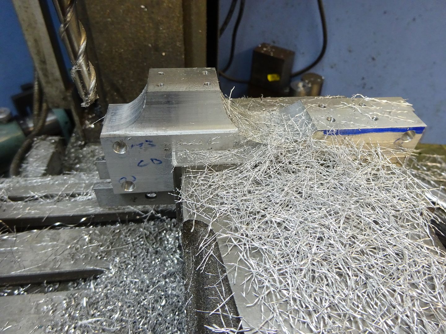
I was up early this morning and managed to get in some practice on the mill, did a bit of a test piece as per the photo. Looks pretty darn good to me. A few comments: A 4-flute TiN cutter will work fine on aluminium alloy. The use of 3-flute cutters is usually recommended to give extra space for swarf. So as you increase chip loads it might be a good idea to go for 3 flutes. The TiN coating will be ok for aluminium, but isn't needed, so no need to pay for it. More esoteric coatings like TiAlN need to run hot (above the melting point of aluminium) to work so are rather less useful. The cutters discussed above seem to be long series? Unless you're taking really deep cuts there's no need to use them. They'll deflect more, and you pay for the side flutes so if you're not going to use them it's a waste. From memory the standard 3-flute 10mm cutter I use has a flute depth of around 22mm. Although not definitive climb milling tends to give a better finish on metals, but not on plastics. It's surprising how big a chip load you can take without breaking a cutter. My mill has around 15 thou backlash and it can grab if I'm over-ambitious, but fingers crossed I haven't broken a cutter yet. I generally leave about 0.5mm for a finish cut with climb milling. It's worth noting that with shallow widths of cut the chip load is much smaller than you might think from the feedrate - search for chip thinning. Generally I cut every which way, I'm too idle to keep winding the handle back to cut in the same direction each time. Andrew
|
| JasonB | 19/10/2018 13:22:15 |
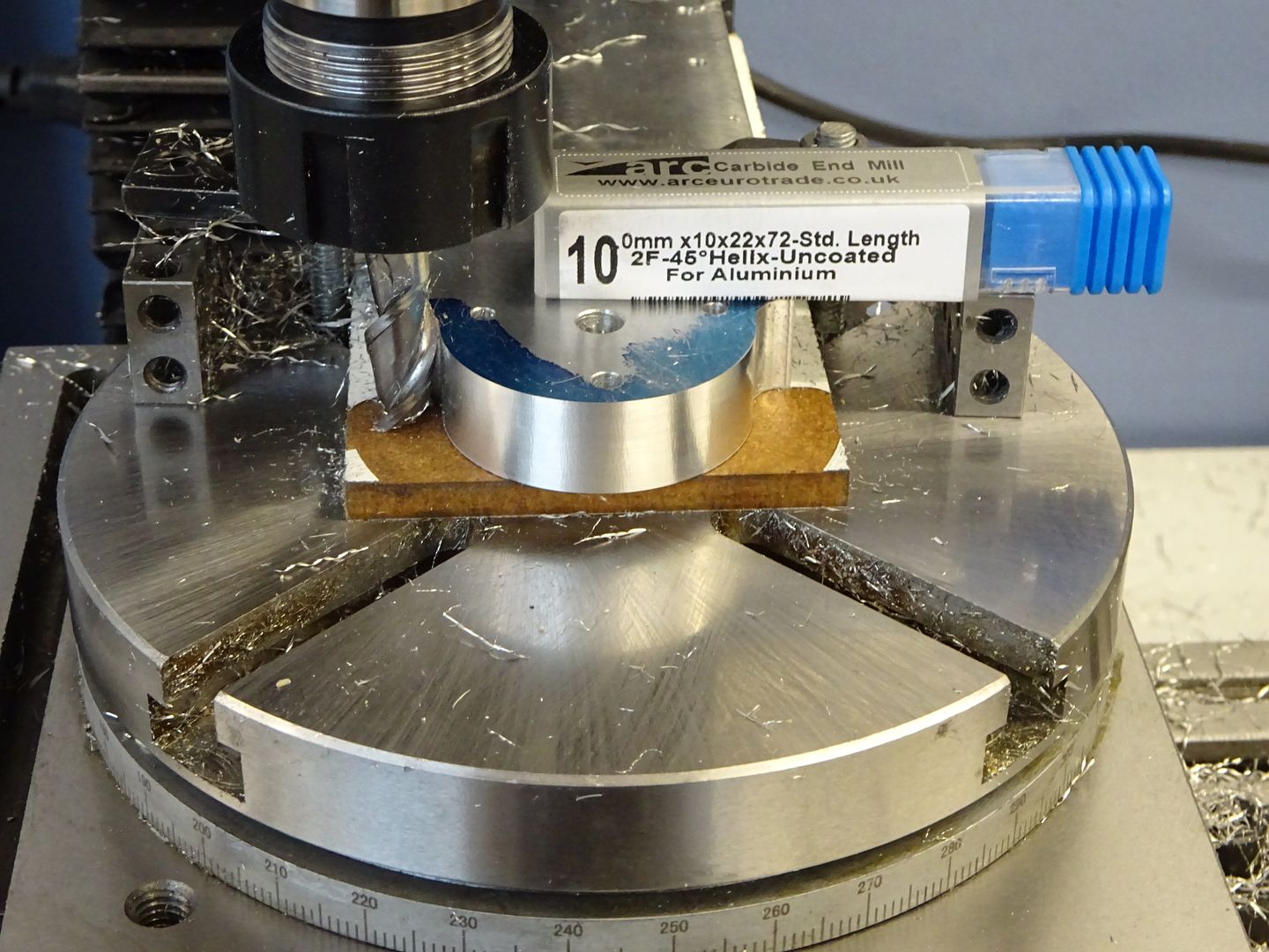
 25215 forum posts 3105 photos 1 articles | As Andrew says the long series ones from ARC are not ideal for all jobs particularly as the diameter gets smaller where you may get some chatter when using just the end of the cutter, hopefully Ketan will add some standard length ones to the range. Even on a long 18mm cut like this there is still a lot of unused flute so shorter will be stiffer and allow greater depth of cut without deflection
In the mean time there are standard length Aluminium specific ones in his carbide range that cut even better than the HSS ones and if looked after will last longer so the slight increase in cost is cancelled out.
|
| Ron Laden | 19/10/2018 15:15:27 |
 2320 forum posts 452 photos | Hi guys, I havnt replied individually but I have taken on board all your advice, many thanks. Jason, a question, how did you cut the radiused sides to the left hand block in your first picture. I imagine you laid it on its side, but what tool did you use. Edited By Ron Laden on 19/10/2018 15:17:49 |
| JasonB | 19/10/2018 15:39:10 |
25215 forum posts 3105 photos 1 articles | Ron, have a look part way down this page for making those parts. |
| Ron Laden | 19/10/2018 16:48:19 |
2320 forum posts 452 photos | Posted by JasonB on 19/10/2018 15:39:10:
Ron, have a look part way down this page for making those parts. Thanks Jason, I would recommend any beginner to read through your Jowitt engine build in the link you provided. It is like a machining guide in itself, I read through all of it and picked up quite a few tips and ideas on "how to do" it will certainly help me. Good ideas I probably wouldnt have thought of: Mounting the feet blocks on a dowel across the vice top and tangental cuts, then finish with a file for a radiused end. Tap mounted in the chuck with the wrench attached for tapping true to the work piece. Packing up the side of the vice for cutting shallow angles. Great stuff Ron Edited By Ron Laden on 19/10/2018 17:00:43 |
| Ron Laden | 19/10/2018 20:17:19 |
2320 forum posts 452 photos | Well they say the proof of the pudding, the temperature in the shop this afternoon went into the 80,s as it did yesterday and the mills X axis tightened up again, which proves its temperature related. I adjusted the gib screws to a balance of smooth operation with the minimum of play in the table. So it will be interesting to see in the morning when the temp is in the 50,s how much the play has increased. Have any of you guys experienced this or is it only me who,s mill has summer and winter gib settings...lol Edited By Ron Laden on 19/10/2018 20:19:00 |
| Andrew Johnston | 19/10/2018 20:41:04 |
7061 forum posts 719 photos | Posted by Ron Laden on 19/10/2018 20:17:19:
Have any of you guys experienced this or is it only me who,s mill has summer and winter gib settings...lol Never noticed it on any of my machines. If the temperature changes are fairly slow I'd expect all parts of the machine to change temperature roughly together. There'd only be a problem if different materials are involved. What are the gib strip, table and body made of? Andrew |
| Ron Laden | 19/10/2018 20:55:10 |
2320 forum posts 452 photos | Andrew, the gib strip is steel and the table and base are cast iron. |
| not done it yet | 19/10/2018 22:50:20 |
| 7517 forum posts 20 photos | Agree with Andrew but one might, pehaps experience a tiny difference if the gib is constrained between the ends and being deformed... only noticed if it is set tight, when cooler, I suppose. All my gibs are the multi-point adjuster type, so not constrained on length. My workshop has not varied by more than a couple of degrees in the last fortnight. That is 2 degrees Celsius, of course, not 16+. |
| Ron Laden | 20/10/2018 08:43:17 |
2320 forum posts 452 photos | Problem found and fixed. The gib was sliding back and forth 3 or 4 mm, it wasnt located on the screw dog points. I removed the gib and it was a bit pathetic to be honest, the 4 dimples for the dog points had no real depth and the positions were off, witness marks from the screws were 1.5mm off centre and all siting at about 2 o'clock. I picked up the witness marks with a small centre drill and drilled 2mm deep with a 2.6mm drill, the dogs are 2.5mm dia but I allowed a couple of thou for fit. Polished the gib and re-fitted, the screws located as they screwed further in. Adjusted until I had a good feel to the the handwheel and managed to get the added bonus of no play in the table. I guess what was happening with the high temperature was that the expansion as tiny as it is was just enough to let the gib slide out of postion as they were not located and then lock up. Ron
Edited By Ron Laden on 20/10/2018 08:44:21 Edited By Ron Laden on 20/10/2018 08:55:54 |
| Russell Eberhardt | 20/10/2018 09:07:52 |
 2785 forum posts 87 photos | This is a common problem with these mills. Try modifying the gib screws as shown in ARC's guide to rebuilding the X1 mill: **LINK** Russell |
| Ron Laden | 20/10/2018 09:23:38 |
2320 forum posts 452 photos | I know I,m a pain but can anyone tell me what these small blocks which are supplied with the vice are used for, I have no idea.
|
| Limpet | 20/10/2018 10:06:44 |
| 136 forum posts 5 photos | Ron I believe they are to fix on the bottom of the vice so you can (supposedly) locate them in the table slot for easy alignment with the table, that's if they fit your table slots. I never bothered with mine preferring to 'clock'the vice in with a dial gauge. Jason I have just read your full jowett build and very impressed, also do you more details of you vice stop how it's fitted. Lionel |
| not done it yet | 20/10/2018 10:14:37 |
| 7517 forum posts 20 photos | They presumably are the locating keys (mentioned as supplied with the vise) so hopefully they will fit into the keyways on your table, when affixed to the bottom of the vise to align the base, either lengthways or crossways. Not much use if you are not using the swivel base, I would think. Edit : not seen the post above - they got there first. Edited By not done it yet on 20/10/2018 10:16:31 |
| Ron Laden | 20/10/2018 10:43:12 |
2320 forum posts 452 photos | Thanks guys but no, they dont fit my table T slots, thanks for identifying anyway. Ron
Edited By Ron Laden on 20/10/2018 10:49:24 |
| Martin Connelly | 20/10/2018 10:46:33 |
 2549 forum posts 235 photos | A bookthat mentions them and may also have other information for you is in this link to Google books. Martin C |
| JasonB | 20/10/2018 16:08:12 |
25215 forum posts 3105 photos 1 articles | As said the blocks go into the grooves in the bottom of the vice or it's swivel base. Unfortunately they make then all the same size irrespective of jaw width and at 14mm will be too big for a lot of hobby bench top mills. A quick tickle with a file suggests they are not that hard so could be milled down to fit your slots leaving a small section at the full 14mm so they still fit snugly in the vice.
Lionel, I'll post some details of my vice stop a bit later. |
| Ron Laden | 20/10/2018 16:56:11 |
2320 forum posts 452 photos | Thanks Jason I will give that a go. I saved a few bob today, I was walking through the cooking section in a cheapie shop when I noticed a shallow sided roasting tray, it reminded me of a mill oil tray certainly not a millions miles from one. I bought it, it will just need 4 holes for the fixing bolts at £2.99 instead of £32 for the mill tray there was no argument. The SX2P uses 8mm T nuts which have a M6 thread, they are quite small, in fact the two I used to fasten down the vice look a bit lost and I used two of the small clamp bars to stop the M6 nuts pulling through the vice fixing slots. I guess they do work but by choice I think I would be happier with M8 threaded nuts. I was thinking of making some but even easier buy the 10mm (M8 thread) T nuts which are just over a tenner for 10 off and modify those. The table slots for the top of the T is a tad over 8mm so M8 rod/bolts will fit but there wouldnt be a lot of wall thickness left in the nut top front and back. Plenty of meat left and right and also plenty in the base of the nut. Think I will get a pair of 10mm nuts and see how they turn out. p.s. Almost forgot to say that the shed was over 80 degrees again this afternoon and no problem with X handwheel so the gib mod did the trick. Ron Edited By Ron Laden on 20/10/2018 17:00:19 |
| JasonB | 20/10/2018 18:19:29 |
25215 forum posts 3105 photos 1 articles | The tee nuts can be quite hard so may not be that easy to alter. |
| Neil Wyatt | 20/10/2018 19:53:28 |
 19226 forum posts 749 photos 86 articles | The slots on my mill are not quite the same width by a thou or three. I milled down the stops for my vice a bit (easy with carbide tool, I think HSS will be OK) and fitted them so that to align my vice I just push them to the back of the slot. Note- your vice may be like mine so that without the swivel vice the slot runs along the length of the vice, which may or may not be what you want. Jason seems to have got lucky and has two-way slots. Obviously if you use them with the swivel vice they will only be as accurate as the alignment of the vice with the base, but you can still remove and replace the vice using them if you don't swivel it. Neil |


Please login to post a reply.
Magazine Locator
Want the latest issue of Model Engineer or Model Engineers' Workshop? Use our magazine locator links to find your nearest stockist!
Sign up to our Newsletter
Sign up to our newsletter and get a free digital issue.
You can unsubscribe at anytime. View our privacy policy at www.mortons.co.uk/privacy
Latest Forum Posts
- *Oct 2023: FORUM MIGRATION TIMELINE*
05/10/2023 07:57:11 - Making ER11 collet chuck
05/10/2023 07:56:24 - What did you do today? 2023
05/10/2023 07:25:01 - Orrery
05/10/2023 06:00:41 - Wera hand-tools
05/10/2023 05:47:07 - New member
05/10/2023 04:40:11 - Problems with external pot on at1 vfd
05/10/2023 00:06:32 - Drain plug
04/10/2023 23:36:17 - digi phase converter for 10 machines.....
04/10/2023 23:13:48 - Winter Storage Of Locomotives
04/10/2023 21:02:11 - More Latest Posts...
- View All Topics
Support Our Partners


Shopping Partners
Subscription Offer

Latest "For Sale" Ads
- Reeves** - Rebuilt Royal Scot by Martin Evans
by John Broughton
£300.00 - BRITANNIA 5" GAUGE James Perrier
by Jon Seabright 1
£2,500.00 - Drill Grinder - for restoration
by Nigel Graham 2
£0.00 - WARCO WM18 MILLING MACHINE
by Alex Chudley
£1,200.00 - MYFORD SUPER 7 LATHE
by Alex Chudley
£2,000.00 - More "For Sale" Ads...
Latest "Wanted" Ads
- D1-3 backplate
by Michael Horley
Price Not Specified - fixed steady for a Colchester bantam mark1 800
by George Jervis
Price Not Specified - lbsc pansy
by JACK SIDEBOTHAM
Price Not Specified - Pratt Burnerd multifit chuck key.
by Tim Riome
Price Not Specified - BANDSAW BLADE WELDER
by HUGH
Price Not Specified - More "Wanted" Ads...
Get In Touch!
Do you want to contact the Model Engineer and Model Engineers' Workshop team?
You can contact us by phone, mail or email about the magazines including becoming a contributor, submitting reader's letters or making queries about articles. You can also get in touch about this website, advertising or other general issues.
Click THIS LINK for full contact details.
For subscription issues please see THIS LINK.
Digital Back Issues


Donate

 Register
 Log-in
Model Engineer Magazine
- Percival Marshall
- M.E. History
- LittleLEC
- M.E. Clock

ME Workshop
- An Adcock
- & Shipley
- Horizontal
- Mill

Subscribe Now
- Great savings
- Delivered to your door

Pre-order your copy!
- Delivered to your doorstep!
- Free UK delivery!
All Forum Topics > Workshop Tools and Tooling > New Mill - Starter Tooling