Forum sponsored by:

The Workshop Progress thread 2018
| JasonB | 31/03/2018 07:30:20 |
 25215 forum posts 3105 photos 1 articles | Looks like you are making good progress to me. I have not done a rocking valve engine but do have one 85% drawn up to make at some time. Edited By JasonB on 31/03/2018 07:30:33 |
| JasonB | 01/04/2018 08:13:07 |
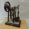
25215 forum posts 3105 photos 1 articles | Made up the Eccentric and valve parts for the Vertical engine I'm working on as and when the fancy takes me.
|
| jimmy b | 01/04/2018 10:24:00 |
 857 forum posts 45 photos | I finally, after 6 years, got to grips with the DRO on Crusader!
I've only ever used it on one tool at a time, because when you power off and move things, the position is lost. I can now just use tool 1 and set the size, the tool library then updates. I even made a setting tool, its just a bit of sleeve with bearings inside. I can just touch the O/D or bore, when the sleeve stops rotating. The size is then just inputted. I may have to buy some more tool holders to take advantage of this!! Its got a 200 tool library after all! I just wish I'd got my head around this sooner!
Jim Edited By jimmy b on 01/04/2018 10:27:16 |
| Muzzer | 01/04/2018 11:46:59 |
 2904 forum posts 448 photos | Don't your scales have index marks on them? As far as I was aware, most do. Then, if you simply move your slides / scales past the index mark after powering up again, the DRO will pick up its absolute coordinates. If you ever shorten your scales, you need to ensure you don't chop off the bit with the index mark otherwise you'll lose the ability to re-zero. Murray |
| Old School | 01/04/2018 12:05:27 |
| 426 forum posts 40 photos | I have over the last few days built this digital timing measuring device for my tether car engines the basis for the unit is a digital angle rule.
|
| Roderick Jenkins | 03/04/2018 22:05:32 |
 2376 forum posts 800 photos |
Edited By Roderick Jenkins on 03/04/2018 22:24:29 |
| JasonB | 04/04/2018 07:16:52 |
25215 forum posts 3105 photos 1 articles | Looks rather good to me already Rod, hope you enjoyed making it as much as I did mine.
Must be the day for finishing engines as the first Muncaster Entablablature engine from my drawings also ran for the first time today. |
| John Haine | 04/04/2018 21:50:14 |
| 5563 forum posts 322 photos | Posted by jimmy b on 01/04/2018 10:24:00:
I finally, after 6 years, got to grips with the DRO on Crusader!
I've only ever used it on one tool at a time, because when you power off and move things, the position is lost. I can now just use tool 1 and set the size, the tool library then updates. I even made a setting tool, its just a bit of sleeve with bearings inside. I can just touch the O/D or bore, when the sleeve stops rotating. The size is then just inputted. I may have to buy some more tool holders to take advantage of this!! Its got a 200 tool library after all!
Jimmy, that's nice. I'm having adventures with tool offsets at the moment too, though on my CNC conversion. Same reason as you, so I can work with multiple tools to get known diameter without having to individually adjust them. My setting aid is different though. How do you deal with run-out of the OD of your sleeve? Does the DRO also work with Z offsets as well as X? I also learned the perils of top slide and tool post movement! My top slide gib screws are now locked solid, and I've installed a dowel between the Dixon tool post and the top slide. I have a big lump of cast iron arriving too to make a base for the Dixon and eliminate the rather unsatisfactory mounting of the Myford S7 topslide, which can also shift under heavy cuts. |
| jimmy b | 05/04/2018 05:37:06 |
857 forum posts 45 photos | John, the run out is a couple of thou, near enough to start, I'll just update it when the tools cut. CNC has been my day job for 20 years, programming, setting and running. Some of that work involves manual tool setting, ("cut and measure"), some how it feels more natural on a CNC! I now prefer not having no compound slide! One of the best mods I've done on the Crusader. Jim Edited By jimmy b on 05/04/2018 05:37:51 |
| Baz | 05/04/2018 10:42:24 |
| 1033 forum posts 2 photos | Nice one Roderick, my one is coming along slowly, very slowly |
| John Haine | 06/04/2018 18:06:25 |
| 5563 forum posts 322 photos | Have been making progress with my tool referencing and homing system on Mach 3 converted lathe. Having previously measured the offsets for a bunch of tools fitted into Dixon indexable holders and set up a tool table, today I wanted to skim about 0.1 mm off the end of my setting bar which was nominally 16mm but actually measured at 15.981 - this with a Mititoyo digital mic that indicates to a micron (I'm sure it's not accurate to that!). It needed cleaning up as during the process of developing Mach3 macros and a referencing screen, tools had been driven into the surface when they shouldn't have! So, switched on the machine, launched Mach 3, homed the X axis (using the switch described on another thread), picked up the end of the bar as a Z reference, used the turning wizard to generate some code to take the bar down to 15.9 mm using a tangential tool in a Diamond holder with the appropriate tool number selected, ran the code, measured the bar with the same micrometer. 15.900 mm indicated. As I said, just how accurate this is is hard to say, but consistent, and considering all the things that had to go right to get this, encouraging. |
| jimmy b | 06/04/2018 18:34:44 |
857 forum posts 45 photos | Posted by John Haine on 06/04/2018 18:06:25:
Have been making progress with my tool referencing and homing system on Mach 3 converted lathe. Having previously measured the offsets for a bunch of tools fitted into Dixon indexable holders and set up a tool table, today I wanted to skim about 0.1 mm off the end of my setting bar which was nominally 16mm but actually measured at 15.981 - this with a Mititoyo digital mic that indicates to a micron (I'm sure it's not accurate to that!). It needed cleaning up as during the process of developing Mach3 macros and a referencing screen, tools had been driven into the surface when they shouldn't have! So, switched on the machine, launched Mach 3, homed the X axis (using the switch described on another thread), picked up the end of the bar as a Z reference, used the turning wizard to generate some code to take the bar down to 15.9 mm using a tangential tool in a Diamond holder with the appropriate tool number selected, ran the code, measured the bar with the same micrometer. 15.900 mm indicated. As I said, just how accurate this is is hard to say, but consistent, and considering all the things that had to go right to get this, encouraging. Sounds good
Jim |
| mechman48 | 07/04/2018 22:48:47 |
 2947 forum posts 468 photos | Did a bit more on my vertical cross engine today, fitted the spool valve rod guide, refitted the swing arms & parallel arms, checked for 'tight spots' all looks good...
|
| TomK | 08/04/2018 16:21:20 |
| 83 forum posts 23 photos | Thought I would put a piece of tooling up I have almost finished. Just have to decide how to finish the jaws. There is more pictures in my album. Tom
|
| John Haine | 08/04/2018 16:41:35 |
| 5563 forum posts 322 photos | That's very nice Tom! |
| Jim Nic | 08/04/2018 19:38:46 |
 406 forum posts 235 photos | Like this George?
I thought it looked better matched to the cylinder Jim |
| mechman48 | 09/04/2018 17:55:00 |
2947 forum posts 468 photos | Posted by Jim Nic on 08/04/2018 19:38:46:
Like this George?
I thought it looked better matched to the cylinder Jim
|
| John Haine | 09/04/2018 18:34:05 |
| 5563 forum posts 322 photos | Made quite a lot of progress liberating a new base to mount my Dickson toolholder block on to the S7 cross slide, generating loads of CI dust in the process. Started with a 135 mm dia backplate casting from RDG. Have now eliminated all the scale turning on the lathe. Photos tomorrow perhaps. On another thread someone showed a base that inspired this project, the casting being from College Engineering - it looks like they don't carry such castings any more, I don't know if that means all their castings are no longer available after the acquisition. Would be a shame. |
| Michael Gilligan | 10/04/2018 07:41:08 |
 23121 forum posts 1360 photos | Posted by TomK on 08/04/2018 16:21:20:
Thought I would put a piece of tooling up I have almost finished. Just have to decide how to finish the jaws. There is more pictures in my album. Tom . That looks very classy, Tom ... is the hemisphere weighted, or is there plenty of friction with the cup ? MichaelG. |
| TomK | 10/04/2018 22:39:07 |
| 83 forum posts 23 photos | Posted by Michael Gilligan on 10/04/2018 07:41:08:
Posted by TomK on 08/04/2018 16:21:20:
Thought I would put a piece of tooling up I have almost finished. Just have to decide how to finish the jaws. There is more pictures in my album. Tom . That looks very classy, Tom ... is the hemisphere weighted, or is there plenty of friction with the cup ? MichaelG. Michael The hemisphere contains 2 ball races and has no weights added the friction on the tufnel base has enough friction to grip the hemisphere. tom
|


.jpg")
.jpg")


This thread is closed.
Magazine Locator
Want the latest issue of Model Engineer or Model Engineers' Workshop? Use our magazine locator links to find your nearest stockist!
Sign up to our Newsletter
Sign up to our newsletter and get a free digital issue.
You can unsubscribe at anytime. View our privacy policy at www.mortons.co.uk/privacy
Latest Forum Posts
- *Oct 2023: FORUM MIGRATION TIMELINE*
05/10/2023 07:57:11 - Making ER11 collet chuck
05/10/2023 07:56:24 - What did you do today? 2023
05/10/2023 07:25:01 - Orrery
05/10/2023 06:00:41 - Wera hand-tools
05/10/2023 05:47:07 - New member
05/10/2023 04:40:11 - Problems with external pot on at1 vfd
05/10/2023 00:06:32 - Drain plug
04/10/2023 23:36:17 - digi phase converter for 10 machines.....
04/10/2023 23:13:48 - Winter Storage Of Locomotives
04/10/2023 21:02:11 - More Latest Posts...
- View All Topics
Support Our Partners


Shopping Partners
Subscription Offer

Latest "For Sale" Ads
- Reeves** - Rebuilt Royal Scot by Martin Evans
by John Broughton
£300.00 - BRITANNIA 5" GAUGE James Perrier
by Jon Seabright 1
£2,500.00 - Drill Grinder - for restoration
by Nigel Graham 2
£0.00 - WARCO WM18 MILLING MACHINE
by Alex Chudley
£1,200.00 - MYFORD SUPER 7 LATHE
by Alex Chudley
£2,000.00 - More "For Sale" Ads...
Latest "Wanted" Ads
- D1-3 backplate
by Michael Horley
Price Not Specified - fixed steady for a Colchester bantam mark1 800
by George Jervis
Price Not Specified - lbsc pansy
by JACK SIDEBOTHAM
Price Not Specified - Pratt Burnerd multifit chuck key.
by Tim Riome
Price Not Specified - BANDSAW BLADE WELDER
by HUGH
Price Not Specified - More "Wanted" Ads...
Get In Touch!
Do you want to contact the Model Engineer and Model Engineers' Workshop team?
You can contact us by phone, mail or email about the magazines including becoming a contributor, submitting reader's letters or making queries about articles. You can also get in touch about this website, advertising or other general issues.
Click THIS LINK for full contact details.
For subscription issues please see THIS LINK.
Digital Back Issues


Donate

 Register
 Log-in
Model Engineer Magazine
- Percival Marshall
- M.E. History
- LittleLEC
- M.E. Clock

ME Workshop
- An Adcock
- & Shipley
- Horizontal
- Mill

Subscribe Now
- Great savings
- Delivered to your door

Pre-order your copy!
- Delivered to your doorstep!
- Free UK delivery!
All Forum Topics > Work In Progress and completed items > The Workshop Progress thread 2018