Forum sponsored by:

How to machine a flywheel ?
Correct positioning on the face plate.
| Rod Neep | 13/04/2016 10:32:58 |
 59 forum posts | Posted by mechman48 on 13/04/2016 09:44:17:
.. funny how we always end up 'making stuff to make stuff with' more than actually 'making stuff'.
George.
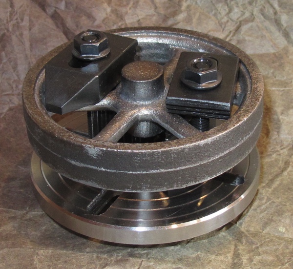
I have sorted out my set up to machine the small 3" flywheel for the Stuart S50. It consists of a couple of spacing blocks to hold the flywheel away from the faceplate, but the smallest clamps that I have are still ungainly....
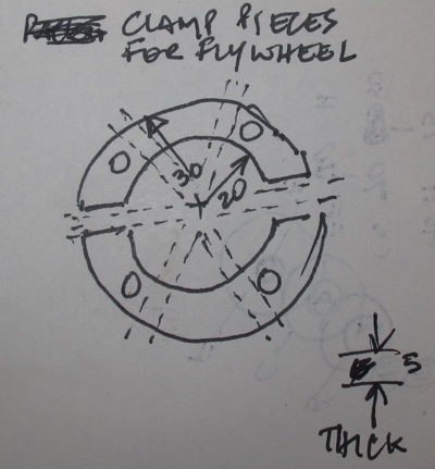
So I am now thinking of making something a little more manageable. I intend to machine a short length of 32mm steel tube (from the scrap box) to act as a spacer, and then ideally a couple of crescent shaped pieces to clamp onto the spokes. If each piece has an outer radius of 30mm and an inner radius of 20mm, leaving a 10mm wide crescent then that would leave space at the centre to machine the boss at the same time. The "fun part" will be trying to figure out how to make the two crescent shaped peices
|
| JasonB | 13/04/2016 10:44:32 |
 25215 forum posts 3105 photos 1 articles | The easiest spacer is a piece of MDF or ply with a rough hole in it to clear the hub and two clearance holes for your bolts. You can machine teh whole face as the tool can run into the MDF. This is the same thing on a larger flywheel that had a lot of bosses on the spokes and being 5 spoke not able to use 3 or 4 jaw chuck.
Crescent shaped clamp plates are also a bit OTT just take two bits of flat bar and drill a clearance hole in them,if you must cut the bar at say 30deg angle. With a small stuart flywheel you may be able to grip by the inside of the rim depending on the size of your 3- jaw chuck, cut to within 0.5mm of the chuck jaws (improvised bed stop helps) and then clean up whats left when you do the other side.
Edited By JasonB on 13/04/2016 10:46:12 |
| Martin Kyte | 13/04/2016 10:47:03 |
 3445 forum posts 62 photos | The potential for the clamps as shown to twist is enormous as the pressure points on the spokes are potentially offset from the line joining the two clamping holes. It would work better as a single ring. regards Martin |
| Rod Neep | 13/04/2016 11:17:17 |
59 forum posts | Posted by JasonB on 13/04/2016 10:44:32:
With a small stuart flywheel you may be able to grip by the inside of the rim depending on the size of your 3- jaw chuck, cut to within 0.5mm of the chuck jaws (improvised bed stop helps) and then clean up whats left when you do the other side. Unfortunately, that will only work with larger flywheels. I do also have a small 80mm chuck, but even that has jaws that won't fit between the spokes of the 3" S-50 flywheel. Cheers |
| Rod Neep | 13/04/2016 11:22:02 |
59 forum posts | Posted by Martin Kyte on 13/04/2016 10:47:03:
The potential for the clamps as shown to twist is enormous as the pressure points on the spokes are potentially offset from the line joining the two clamping holes. It would work better as a single ring. regards Martin That's a better idea. Thanks. What I would like to do is have one clamping piece which will also allow me get a tool in to face the boss and also turn down its diameter, as well as enabling me to machine the outer rim of the flywheel. How to make that single ring (60mm diameter and with a hole 40mm) and find the right material to do it? Cheers, Rod Edited By Rod Neep on 13/04/2016 11:24:56 |
| Andrew Johnston | 13/04/2016 11:35:16 |
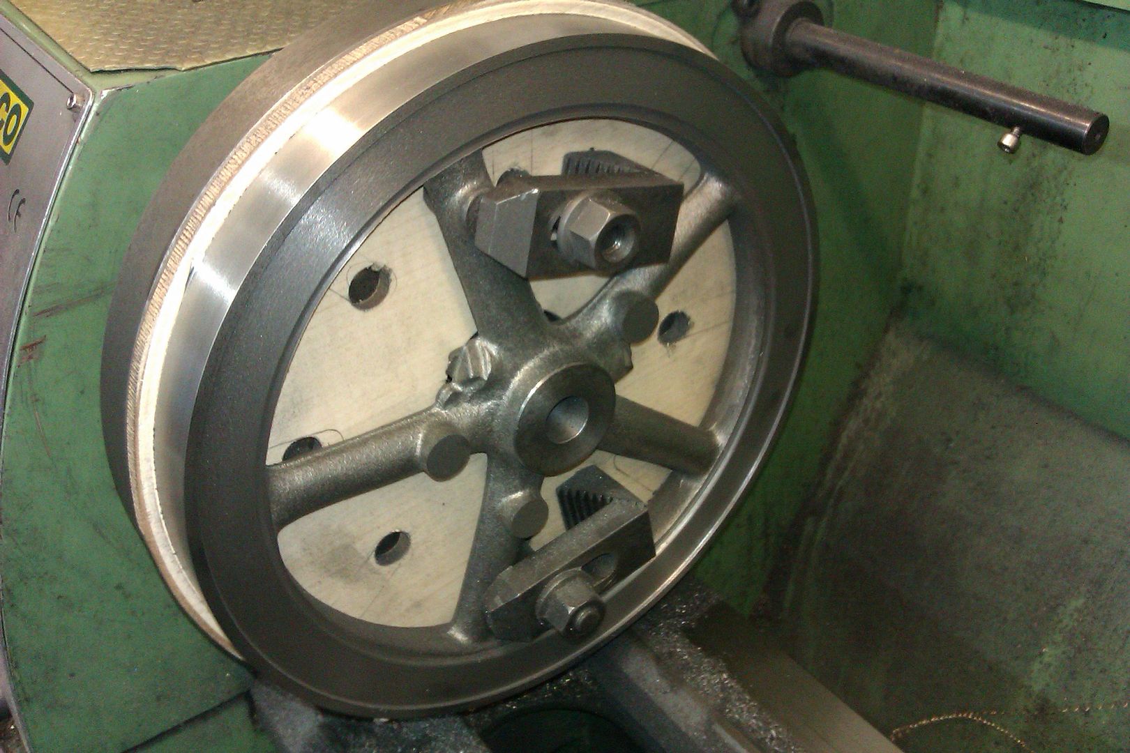
 7061 forum posts 719 photos | This is how I machined the flywheels for my traction engines:
The rim sits on three blocks of scrap aluminium. The two steel spigots at 1 and 7 o'clock partially locate the flywheel. Crucially they also provide the driving force. So the clamps on the spokes are only there to stop the flywheel falling off the faceplate. Since they do not provide the drive, via friction, they don't need to be done up tightly with the risk of cracking the spokes. Andrew |
| Martin Kyte | 13/04/2016 11:49:47 |
3445 forum posts 62 photos | Out of interest, when was the last time anyone had something move when machining. I suspect we go overboard with our clamping. OK maybe if you are using a big horizontal mill and ganging up on a casting with large diameter side and face cutters you really need to provide some major clamping force but for the small cuts we normally are involved in? I'm sure I go overboard with bolting stuff down but when you realize what you can machine with just double side tape or applying pressure from a revolving centre with the workpiece up against a faceplate you do begin to wonder if we go a little over the top. regards Martin
|
| Brian John | 13/04/2016 12:00:10 |
| 1487 forum posts 582 photos | As long as you have enough hub to grip in the lathe chuck to get started then surely with a small flywheel of less than 3 inches it is easier to machine it using a mandrel ? Does this method produce an inferior finish as compared with using a faceplate ? |
| Neil Wyatt | 13/04/2016 16:05:37 |
 19226 forum posts 749 photos 86 articles | Posted by Martin Kyte on 13/04/2016 11:49:47:
Out of interest, when was the last time anyone had something move when machining.
Well it's never happened to me |
| Steve Withnell | 13/04/2016 16:19:10 |
 858 forum posts 215 photos | Posted by Neil Wyatt on 13/04/2016 16:05:37:
Posted by Martin Kyte on 13/04/2016 11:49:47:
Out of interest, when was the last time anyone had something move when machining.
Well it's never happened to me It's usually accompanied by an old english expression, something like "Oh dear me". Which is never heard in my shed. Steve
|
| Andrew Johnston | 13/04/2016 22:41:43 |
7061 forum posts 719 photos | Posted by Martin Kyte on 13/04/2016 11:49:47:
Out of interest, when was the last time anyone had something move when machining. It happens now and again.
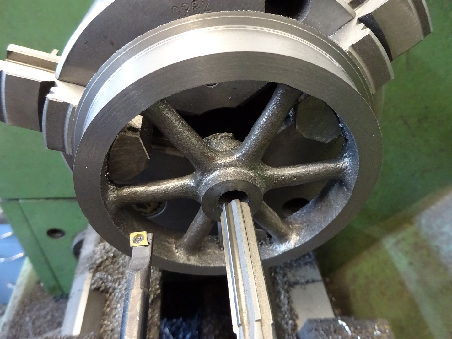
Simple operations like drilling and reaming can require complicated clamping to stop the work moving:
It's a matter of thinking about where the cutting forces are being exerted and making sure that they are reacted by clamps or blocks. I take the view that if I have x horsepower to play with on a machine I want to use x horsepower to remove metal, if the work and tool will cope. If you don't hear the motor start straining when the cut starts then you're not trying hard enough! Andrew |
| Nigel McBurney 1 | 14/04/2016 20:54:07 |
 1101 forum posts 3 photos | Faceplates,why do manufacturers continue to produce plates with 4 primary slots,when a lot engineering work is divided into 3 or 6 e.g. flywheels ,it probably throws back to the olden days when face plates could take removable jaws so you could have a 4 jaw chuck or a faceplate all in one,Colchester did make standard faceplate with 3 primary slots but continued to make the larger plate with 4 primary slots which are a b nuisance when machining 6 spoke flywheels. On larger flywheels it does pay to rough out the flywheel and leave it for some time,the longer the better to ensure any inbuilt stresses get a chance to relax. when trying to machine a small flywheel ,it does pay to drill the hub and then bore with a boring tool even down to small diameters prior to reaming, it does reduce flywheel wobble.I noted in previous posts the mention of the finish of the bore being polished when fitting shafts and the bore increasing slightly in diameter, i usually bore very slightly oversize on larger flywheels then finish the diameter to size with a hone.The aim should be machine as much as possible at one setting to get true running flywheels,if the flywheels are secured by tapered key the the flywheel should be tight on the shaft,a really tight wring on fit or needing the pull of a couple of bits of studding to draw it onto the shaft, if not the tapered key will put pressure on one side of the hub and induce a wobble. Crossleys were one manufacturer who made a lot of 5 spoke flywheels, the position of the spokes relative to the crank helped to balance the engine,and some times a slot was cast into the inside of the rim for balacing purposes. |
| Martin Kyte | 15/04/2016 09:13:25 |
3445 forum posts 62 photos | "i usually bore very slightly oversize on larger flywheels then finish the diameter to size with a hone" That's a good trick, where can I get hones that put metal on? ;0) Martin |
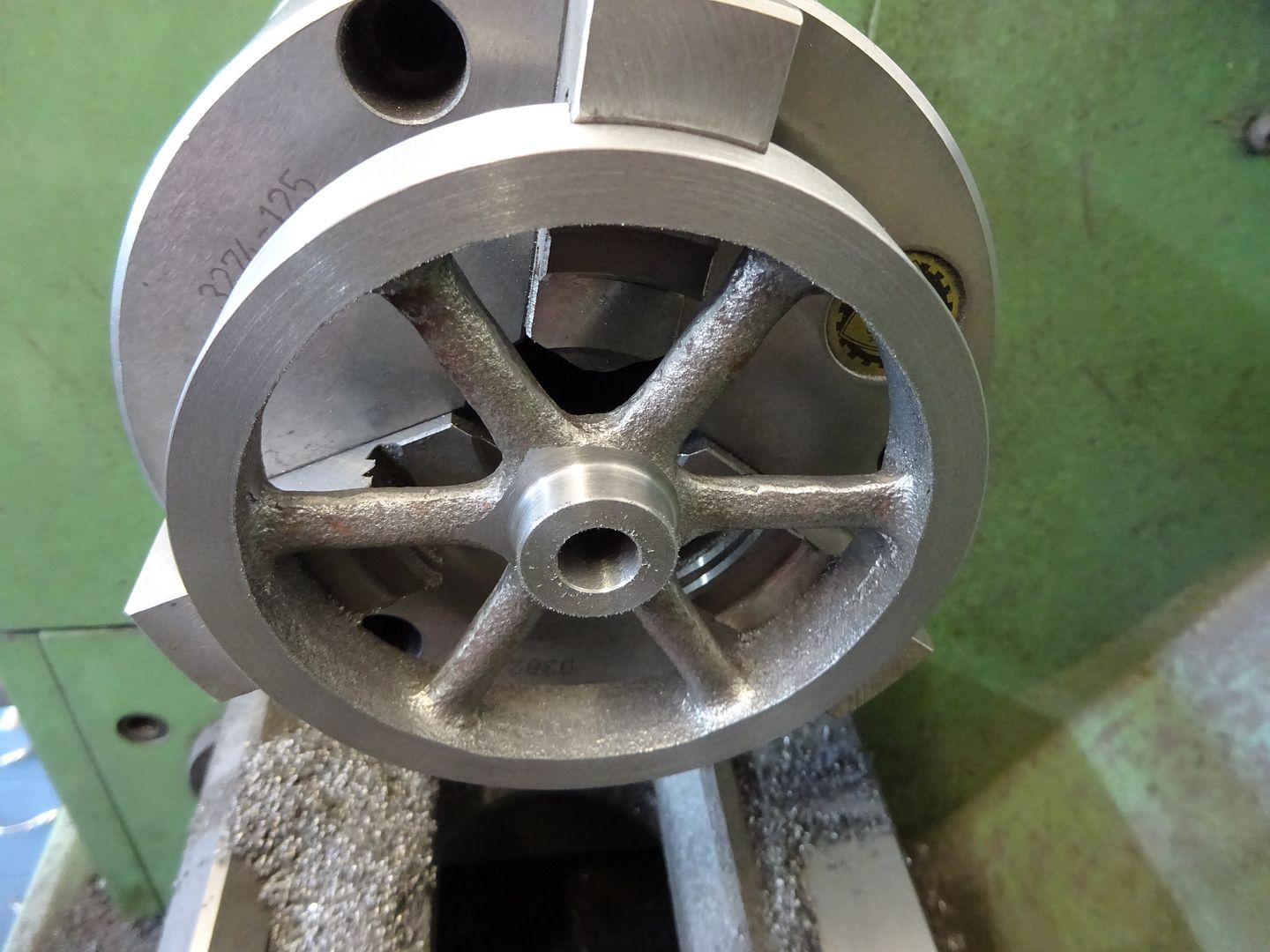
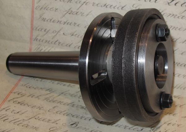
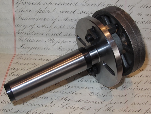
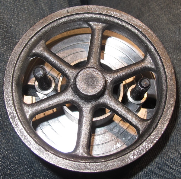
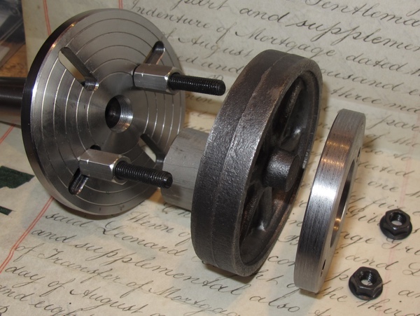
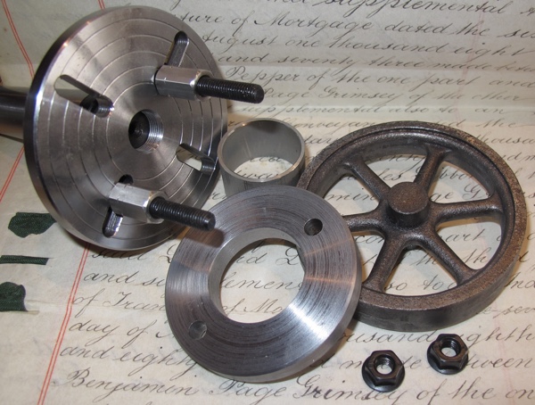
| Rod Neep | 21/04/2016 12:38:15 |
59 forum posts | I have come a long way on from my first thoughts. One solution to setting up to machine a small (3 inch) cast flywheel. The problem being is that most face plates are too large and are unable to hold such a small item.
What I have here is a Unimat faceplate attached to a 3MT (12mm Emco thread) arbour, so that it will fit into my lathe. That's the face plate taken care of.... And next, the clamping of the flywheel: I made a support "spacer" from 32mm diameter stainless steel tube (because I had some lying around). That supports all 6 spokes. A "disc" clamping plate is a little smaller than the inner rim of the flywheel to spread the load over all of the flywheel spokes. and allows a little "tapping room" to get the flywheel centred. The round clamping plate has a large hole at the centre so that I can get in to machine the boss of the flywheel.
The steel tube (supporting the spokes) spaces the flywheel away from the faceplate to facilitate machining the back outer edge.
Rod Edited By Rod Neep on 21/04/2016 12:38:51 |
| Brian John | 21/04/2016 12:45:29 |
| 1487 forum posts 582 photos | That looks very interesting ; thank you for posting those photos. I have just finished machining a cast iron flywheel of the same size but I used the mandrel method. I could not get a mirror finish with my cutting tools so I had to spend two hours polishing it up with 400 grit wet and dry. What tools will you use to machine the flywheel...do you have special cutting tools for cast iron ? I do not remember having any problems machining a similar cast iron flywheel a few months ago. The cast iron ''felt'' quite different this time ; it was much ''softer''.
Edited By Brian John on 21/04/2016 12:46:53 |
| Rod Neep | 22/04/2016 00:42:47 |
59 forum posts | To be honest, I have no idea. Really I am a rank beginner at this stuff, and the only cast iron that I have machined so far is a back plate for a new chuck. The finish was "fair". There are many much more experienced folks on here to answer your question. Rod |
| Brian John | 10/05/2016 10:21:49 |
| 1487 forum posts 582 photos | 1. I have machined about a dozen aluminium, brass and cast iron flywheels using the mandrel method and had no problems. But my last cast iron flywheel has a distinct wobble. I put it back on the mandrel to machine the sides again and it looked okay on the lathe but putting it back on the axle has shown that it still wobbles. What went wrong here and is there any way to fix this ? 2. I did intend to use a face plate for the first time but for 80mm flywheels there is no room : the holes to clamp the flywheel are too far out from the center of the face plate (they lie under the rim of the flywheel) and I cannot drill new holes in the correct place on the face plate as this would put the holes through the recess where it attaches to the lathe. I might be missing something here ? Edited By Brian John on 10/05/2016 10:22:23 |
| Ian S C | 10/05/2016 13:06:21 |
 7468 forum posts 230 photos | Brian, you can make a false wooden/MDF face plate that can be screwed on to the metal one, with the flywheel bolted to the wooden one. With that set up you can finish the outside , and one face of the FW and it doesn't matter if you take a bit out of the wood. For the hole you really should drill through a good bit smaller than full size, then bore it with a boring bar to a few thou under size, then ream it to size unless you feel you can bore it spot on. Your wobbly one might need the boring bar and a bush to bring the hole back to size. The pulleys, and flywheels for my engines are mostly bored out to 3/8", and I use bushes with a split to bring the size down if I use them on a motor with a smaller shaft. Ian S C |
| Brian John | 10/05/2016 13:15:02 |
| 1487 forum posts 582 photos | ''Bushes with a split'' : do you have a photo please ? The wooden face plate is a good idea ; I am thinking about that now. |
| Owain Samuel | 11/05/2016 21:06:23 |
| 18 forum posts 10 photos | Not a flywheel (actually a large angle plate) but here's an idea of mine (probably not original) that makes setting stuff true on a faceplate easier. First clamp the item to the face plate with a drawbar through the spindle (doesn't have to be anything fancy, mine was a length of studding and a bush to fit the outboard end of the spindle. Just nip this, it's then easy to tap the work about and set true (no clamps fighting back, no aligning bolts with slots and spokes/holes) Once true, add suitable clamps/bolts/gaffer tape (delete as applicable) and machine away. The drawbar can be left in place as a extra as well, or removed if there's a central bore to machine. Just an idea.. Owain
|


Please login to post a reply.
Magazine Locator
Want the latest issue of Model Engineer or Model Engineers' Workshop? Use our magazine locator links to find your nearest stockist!
Sign up to our Newsletter
Sign up to our newsletter and get a free digital issue.
You can unsubscribe at anytime. View our privacy policy at www.mortons.co.uk/privacy
Latest Forum Posts
- hemingway ball turner
04/07/2025 14:40:26 - *Oct 2023: FORUM MIGRATION TIMELINE*
05/10/2023 07:57:11 - Making ER11 collet chuck
05/10/2023 07:56:24 - What did you do today? 2023
05/10/2023 07:25:01 - Orrery
05/10/2023 06:00:41 - Wera hand-tools
05/10/2023 05:47:07 - New member
05/10/2023 04:40:11 - Problems with external pot on at1 vfd
05/10/2023 00:06:32 - Drain plug
04/10/2023 23:36:17 - digi phase converter for 10 machines.....
04/10/2023 23:13:48 - More Latest Posts...
- View All Topics
Support Our Partners


Shopping Partners
Subscription Offer

Latest "For Sale" Ads
- Reeves** - Rebuilt Royal Scot by Martin Evans
by John Broughton
£300.00 - BRITANNIA 5" GAUGE James Perrier
by Jon Seabright 1
£2,500.00 - Drill Grinder - for restoration
by Nigel Graham 2
£0.00 - WARCO WM18 MILLING MACHINE
by Alex Chudley
£1,200.00 - MYFORD SUPER 7 LATHE
by Alex Chudley
£2,000.00 - More "For Sale" Ads...
Latest "Wanted" Ads
- D1-3 backplate
by Michael Horley
Price Not Specified - fixed steady for a Colchester bantam mark1 800
by George Jervis
Price Not Specified - lbsc pansy
by JACK SIDEBOTHAM
Price Not Specified - Pratt Burnerd multifit chuck key.
by Tim Riome
Price Not Specified - BANDSAW BLADE WELDER
by HUGH
Price Not Specified - More "Wanted" Ads...
Get In Touch!
Do you want to contact the Model Engineer and Model Engineers' Workshop team?
You can contact us by phone, mail or email about the magazines including becoming a contributor, submitting reader's letters or making queries about articles. You can also get in touch about this website, advertising or other general issues.
Click THIS LINK for full contact details.
For subscription issues please see THIS LINK.
Digital Back Issues


Donate

 Register
 Log-in
Model Engineer Magazine
- Percival Marshall
- M.E. History
- LittleLEC
- M.E. Clock

ME Workshop
- An Adcock
- & Shipley
- Horizontal
- Mill

Subscribe Now
- Great savings
- Delivered to your door

Pre-order your copy!
- Delivered to your doorstep!
- Free UK delivery!
All Forum Topics > Stationary engines > How to machine a flywheel ?