Forum sponsored by:

The Workshop Progress thread 2018
| duncan webster | 19/02/2018 17:32:48 |
| 5307 forum posts 83 photos | I've always wondered how you get the sloping stay bar (which I assume goes on the left hand side) to line up properly. I can see how you would get the angle the same on the base and cylinder support bits, but getting them coaxial? Perhaps Jason could enlighten us. |
| JasonB | 19/02/2018 18:47:27 |
 25215 forum posts 3105 photos 1 articles | The joys of CAD Yes you assume correctly, there will be a stay to support that side of the cylinder.
I'm sure that back in the day the draftsman would have drawn it out and then dug out his slide rule and log tables to calculate lengths and angles. But CAD means we can keep out socks on. What I did was to draw a circle centrally on the pad where the rod will fix to the base and projected this upwards as shown by the blue shaft. I also drew part of the cylinder support at the correct height above the base.
I then treated this blue shaft as a cut (drilled hole) which cut a hole in all it passed through therefore giving me a hole in the cylinder support. I can then measure from the central axis to the ctr of this hole which gives me it's exact position which can be used when it comes to producing the 2D working drawings and then the actual part.
Once all the parts are assembled it is also possible to check for any interferences, here I have moved the hole by 0.01mm and the CAD shows the clash in orange which I have arrowed in blue. This is for a 4mm spigot on the end of the shaft into a 4mm hole, in reality I will drill with a bit more clearance than I would for a normal fixing as there are bound to be slight differences between theoretical and actual positions.
The Cad also lets me check that nothing hits as the engine turns over which I can simply do by holding the mouse button down on a rotating or sliding part and moving it about.
|
| Jim Nic | 20/02/2018 10:21:52 |
 406 forum posts 235 photos | My current project is Ray Hasbrouk's No 3 Rocking Valve Engine. This is a fairly simple engine with not a lot of moving features so I decided to reduce it's size. I did this by converting the imperial dimensions on the drawing to metric using a 15mm to the inch conversion factor. After a set back involving a small BA tap and a ruined cylinder I have made a couple of design changes to allow the use of larger threads than the reduction in size called for and now have a completed cylinder assembly.
Jim |
| JasonB | 20/02/2018 13:09:56 |
25215 forum posts 3105 photos 1 articles | Looks good Jim
Interesting choice of reduction, was there a particular reason for going with 15mm/1" ? I have done similar and found that 1mm to 1/16" works out nicely to round numbers and gives a very similar size reduction of 16mm/inch |
| Jim Nic | 20/02/2018 16:15:58 |
406 forum posts 235 photos | Jason I went with that conversion for 2 reasons: 1. I happened to have a flywheel about 3/5 of the original design size. 2. I wanted to convert the imperial dimensions I had on the drawing to metric so I made a spreadsheet and 15 was a convenient number to end up where I wanted to be and seemed the logical way to do it. 3. I never thought of working the other way (which now you mention it would have been a heck of a lot simpler) I wish now I had asked for advice on here, but next time .......... Jim |
| mechman48 | 22/02/2018 19:34:10 |
 2947 forum posts 468 photos | Well caught up a little with my Vertical cross, completed the swing arms, machined up the crosshead & did a trial assembly... looks fine so far... |
| JasonB | 26/02/2018 18:51:08 |
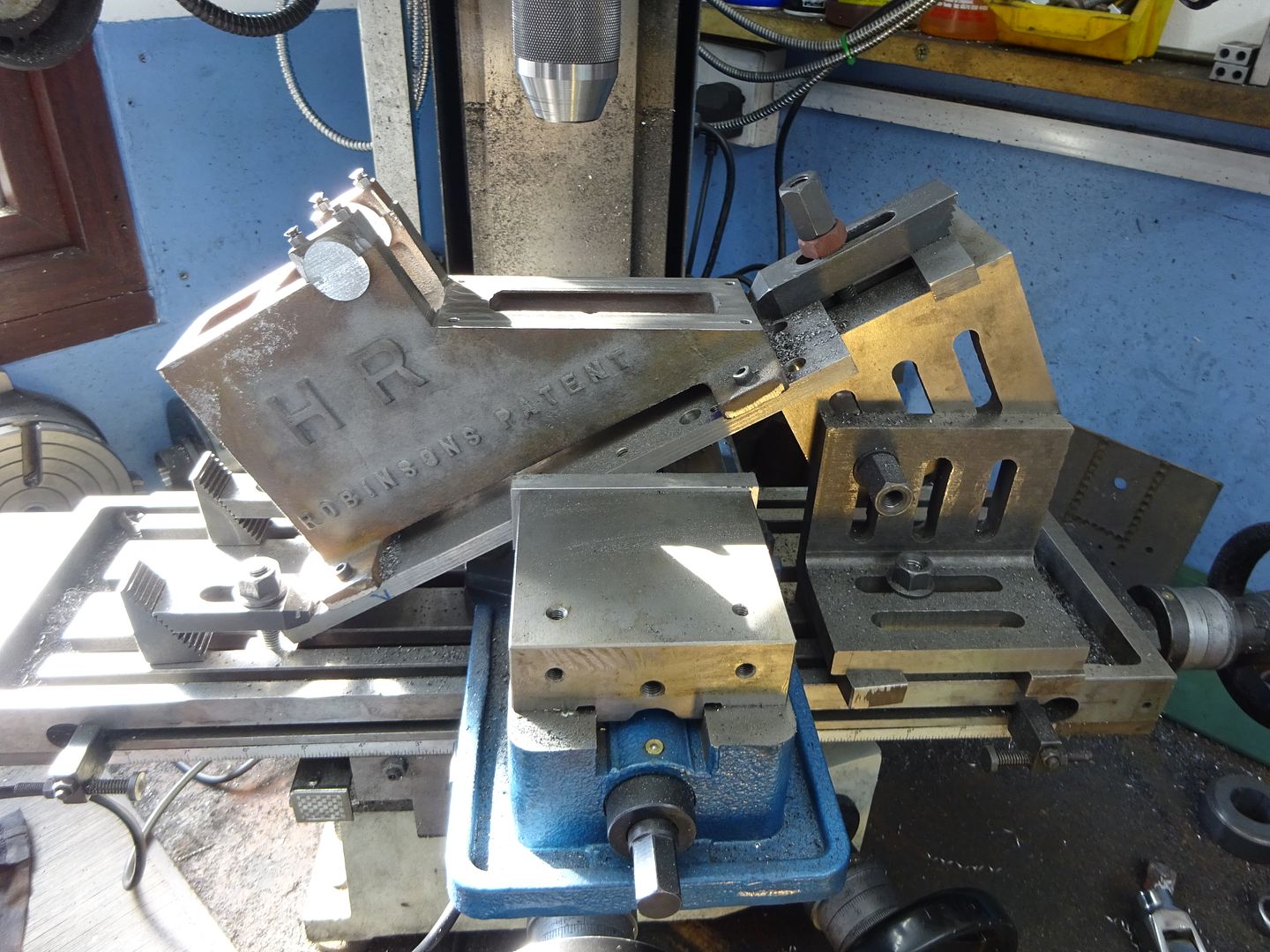
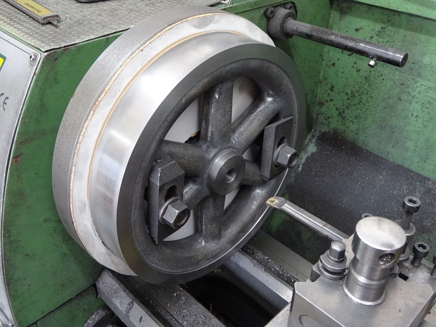
25215 forum posts 3105 photos 1 articles | The Postman dropped off some castings for the 1/2 scale Robinson X-Type last week so thought I may as well machine them up. Fairly straightforward work on the base casting and bearing caps but as these were reject castings from when Alyn Foundry were trading and had been sitting in Graham Corey's damp workshop for several years there were a few flaws and a lot of chilled areas which slowed progress.
The 8.5" Flywheel was not too bad, just a couple of voids on the other side that will need filling and mean I will probably have to go with a painted rim but will make a pulley which can be left bright.
Edited By JasonB on 26/02/2018 18:53:45 |
| Muzzer | 26/02/2018 22:02:36 |
 2904 forum posts 448 photos | Finally machined up the cover plate for my X axis housing. I had this ready to go a week ago before I buggered my back. Turned out OK but I'm seriously pigged off with the alleged chamfer tool - I'd be better off with a countersink drill. Don't recall much about its parentage but I've struggled to find any uncoated carbide chamfer mills in the UK, so ended up ordering some from Aliexpress. After all, they really can't be any worse.
That's probably the last job I'll be doing on this machine with the Chinese controller. I've just taken delivery of a Centroid Acorn controller which will be going on the Shizuoka and the Chinese controller will be moving over onto the Bridgeport. It's not a bad deal for £400 but even for someone who is used to working with Chinese, the machine translated documentation is truly insurmountable. Murray |
| Brian O'Connor | 01/03/2018 11:23:36 |
| 74 forum posts 19 photos | Just finished honing and lapping the cylinder and piston of my Star Hit & Miss engine to get a nice sliding fit. A first assembly and it's starting to look like an engine. The iron castings were a delight to machine, no blow holes, no chilled margins and all the lumps and bumps very accurately placed. Still a long way to go though. B
Edited By JasonB on 01/03/2018 17:48:35 |
| JasonB | 01/03/2018 12:11:01 |
25215 forum posts 3105 photos 1 articles | Looks good Brian, the start is a nice engine. |
| Brian O'Connor | 01/03/2018 16:51:40 |
| 74 forum posts 19 photos | Thanks, Jason. You could probably built two of these by now. When viewing the photo I realised that in reducing the size I had got the aspect ratio wrong. The image in my album has been corrected and although it has the same name as before, my post above cannot find it and I can not find any way of editing my post. Can you help restore the picture please? B |
| Brian O'Connor | 01/03/2018 20:08:04 |
| 74 forum posts 19 photos | Many thanks, Jason, for sorting the picture. B |
| JasonB | 03/03/2018 20:21:54 |
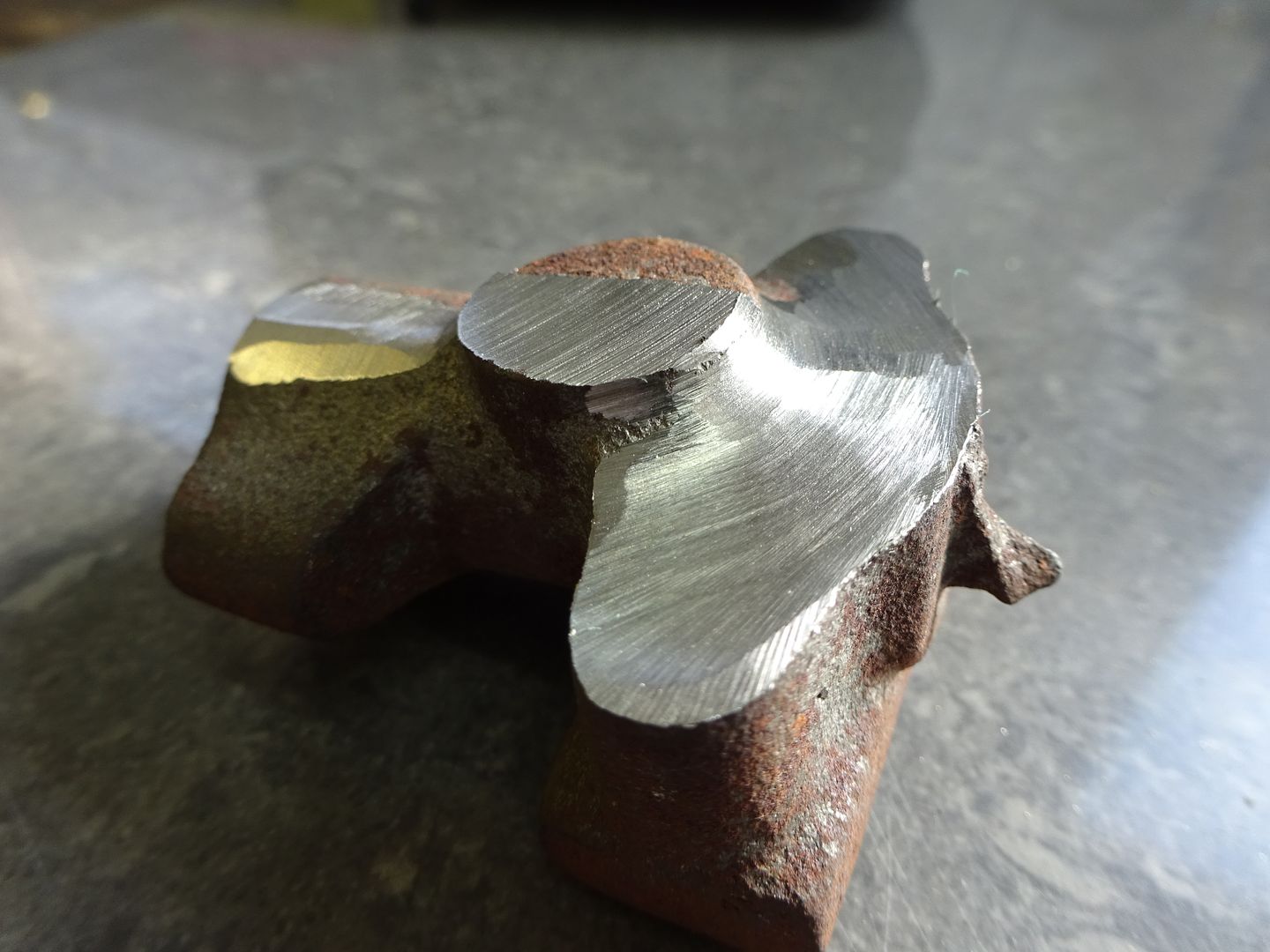
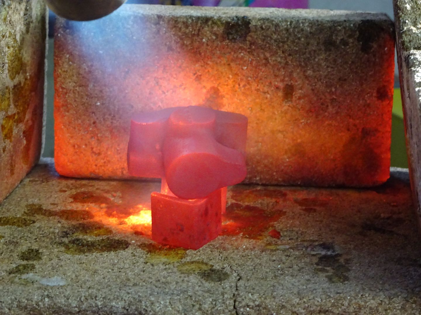
25215 forum posts 3105 photos 1 articles | I got a reject casting for the X-type exhaust block that had been consigned to a dark corner due to excess casting misalignment, some initial reshaping with the angle grinder suggested it may be a bit of a chilled casting so befoer doing any machining it was heated for 15mins and then allowed to cool slowly.
That did the trick and it machined up nicely today, also got exhaust valve, spring collet, tappet, eccentric rod guide and end plug done and now have an exhaust assembly that works from the epicyclic gearbox.
No 4-jaw chucks were used in the making of these parts or 3-jaws ones for that matter. All turning in the 5C and the micrometer made a rare appearance to measure the valve stem Edited By JasonB on 03/03/2018 20:25:36 |
| Roderick Jenkins | 04/03/2018 16:56:01 |
 2376 forum posts 800 photos | I decided I needed some mods to my little Denford/Sherline CNC mill to make it truly usable so I have added some bellows to protect the Y leadscrew, a sub table for easier attachment of the workpiece and a blower to stop the swarf choking the cutter.
Here's a little bit of video of the blower in action. My little airbrush compressor can keep up a constant 30psi through this nozzle which seems to work OK.  Edited By Roderick Jenkins on 04/03/2018 16:58:42 |
| JasonB | 04/03/2018 17:08:21 |
25215 forum posts 3105 photos 1 articles | That's the second one today |
| John Haine | 04/03/2018 17:14:18 |
| 5563 forum posts 322 photos | I added a blower to my Novamill for the same reason - I also had to fit a polycarb sheet using magnets to hold it to avoid chips going everywhere in the workshop. (I removed the standard perspex cover as I just didn't have room.) Tend to get little chip-drifts in the back of the housing! Also used an airbrush compressor, but mine didn't have a tank so repurposed a used Bernzomatic oxygen bottle to provide a little bit of a reservoir. |
| Hopper | 05/03/2018 11:16:43 |
 7881 forum posts 397 photos |
Bit of progress on the Potty "Lads and Dads" mill engine. The lad is learning a lot. One thing he learned is to check the table on the Chinese drill press for square to the spindle before drilling and reaming a crankshaft. Then he learned how to use a parting tool ground like a turning tool to get in between the webs of teh finished crank and turn the crankpin back true to to the mainshafts. And then how to bodgy up a Chinese drill press with bits of shim to bring the table back to square for next time. He's now using the 60 year old Myford lathe and vertical slide for any drilling that needs to be dead-on. So far the engine has come up looking rather well with a flywheel made from an old steam valve handwheel and various bits of scrap brass used to tart things up a bit. Probably will paint that valve chest green along with the cylinder eventually, maybe leave the one side with the nuts etc on it as brass, just for show, ditto the cyl. heads. Paintwork is official Colorbond household roof guttering green left over from an ancient domestic touch up job. Edited By Hopper on 05/03/2018 11:27:12 |
| Another JohnS | 05/03/2018 13:20:10 |
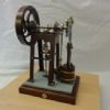
| 842 forum posts 56 photos | Shay complete - with the exception of testing the DAG Brown injectors that are almost complete. Will test this summer, as it's too cold outside to do any steaming up, and I don't have an electric test boiler. It's to Kozo Hiraoka's first 3-1/2" gauge Shay design, with the exception of a displacement lubricator on the RHS running board, and an injector as opposed to an axle pump. A fun project!
|
| Roderick Jenkins | 05/03/2018 19:26:44 |
2376 forum posts 800 photos | That's looking very nice John. I'm sure she'll go as well as she looks. Rod |
| Neil Wyatt | 05/03/2018 20:43:20 |
 19226 forum posts 749 photos 86 articles | Well done John, looks great. How long did it take you? Neil |


.jpg")
.jpg")
.jpg")


This thread is closed.
Magazine Locator
Want the latest issue of Model Engineer or Model Engineers' Workshop? Use our magazine locator links to find your nearest stockist!
Sign up to our Newsletter
Sign up to our newsletter and get a free digital issue.
You can unsubscribe at anytime. View our privacy policy at www.mortons.co.uk/privacy
Latest Forum Posts
- hemingway ball turner
04/07/2025 14:40:26 - *Oct 2023: FORUM MIGRATION TIMELINE*
05/10/2023 07:57:11 - Making ER11 collet chuck
05/10/2023 07:56:24 - What did you do today? 2023
05/10/2023 07:25:01 - Orrery
05/10/2023 06:00:41 - Wera hand-tools
05/10/2023 05:47:07 - New member
05/10/2023 04:40:11 - Problems with external pot on at1 vfd
05/10/2023 00:06:32 - Drain plug
04/10/2023 23:36:17 - digi phase converter for 10 machines.....
04/10/2023 23:13:48 - More Latest Posts...
- View All Topics
Support Our Partners


Shopping Partners
Subscription Offer

Latest "For Sale" Ads
- Reeves** - Rebuilt Royal Scot by Martin Evans
by John Broughton
£300.00 - BRITANNIA 5" GAUGE James Perrier
by Jon Seabright 1
£2,500.00 - Drill Grinder - for restoration
by Nigel Graham 2
£0.00 - WARCO WM18 MILLING MACHINE
by Alex Chudley
£1,200.00 - MYFORD SUPER 7 LATHE
by Alex Chudley
£2,000.00 - More "For Sale" Ads...
Latest "Wanted" Ads
- D1-3 backplate
by Michael Horley
Price Not Specified - fixed steady for a Colchester bantam mark1 800
by George Jervis
Price Not Specified - lbsc pansy
by JACK SIDEBOTHAM
Price Not Specified - Pratt Burnerd multifit chuck key.
by Tim Riome
Price Not Specified - BANDSAW BLADE WELDER
by HUGH
Price Not Specified - More "Wanted" Ads...
Get In Touch!
Do you want to contact the Model Engineer and Model Engineers' Workshop team?
You can contact us by phone, mail or email about the magazines including becoming a contributor, submitting reader's letters or making queries about articles. You can also get in touch about this website, advertising or other general issues.
Click THIS LINK for full contact details.
For subscription issues please see THIS LINK.
Digital Back Issues


Donate

 Register
 Log-in
Model Engineer Magazine
- Percival Marshall
- M.E. History
- LittleLEC
- M.E. Clock

ME Workshop
- An Adcock
- & Shipley
- Horizontal
- Mill

Subscribe Now
- Great savings
- Delivered to your door

Pre-order your copy!
- Delivered to your doorstep!
- Free UK delivery!
All Forum Topics > Work In Progress and completed items > The Workshop Progress thread 2018