Forum sponsored by:

Restoring Beaver VBRP Mill
Documenting strip and rebuild of this English built milling machine
| Paul Major | 09/02/2014 23:31:57 |
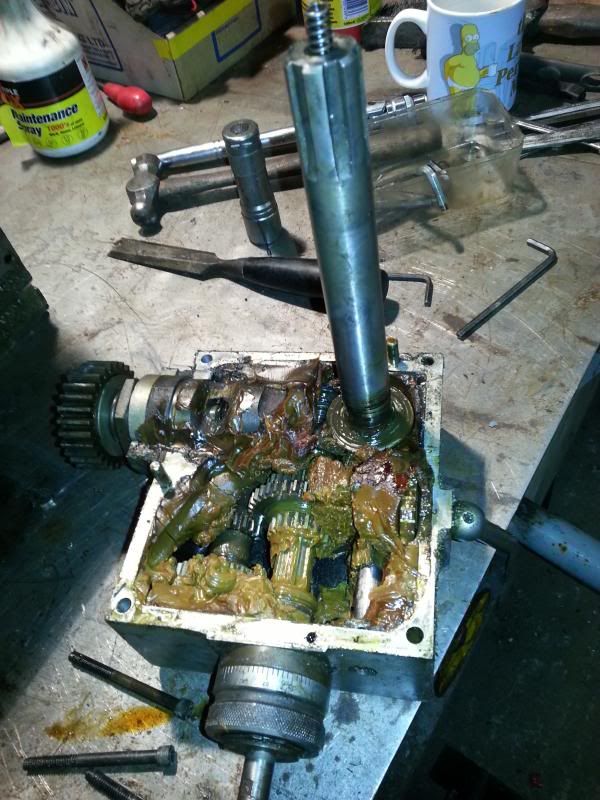
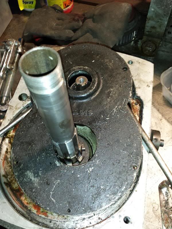
| 53 forum posts 13 photos | With the quill out the next part to remove was the feed gearbox.
Grease, grease and more grease View down the quill housing
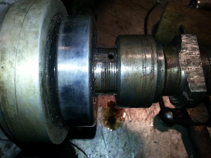
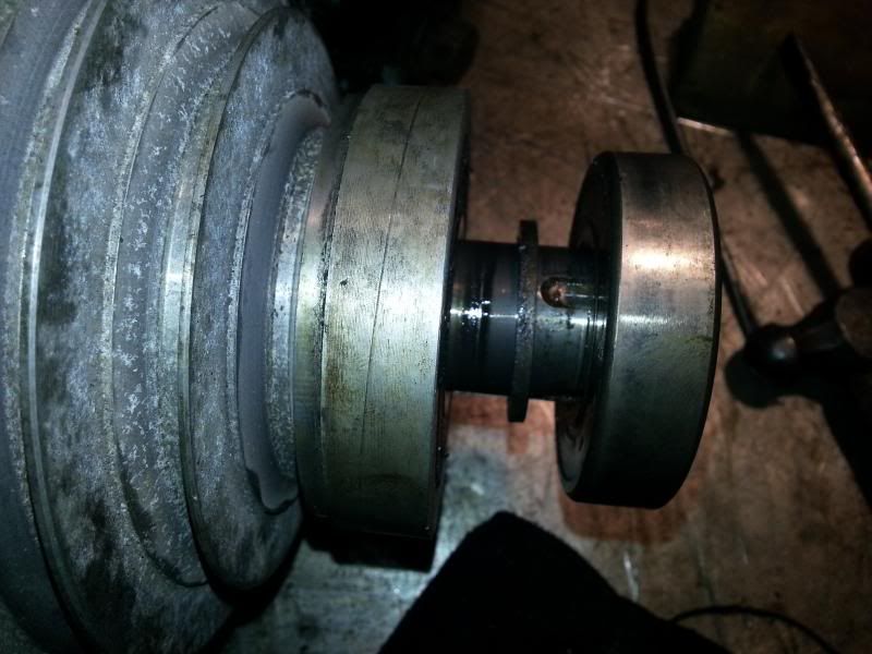
With the quill and gearbx outta the way I turned my attention back to the top part of the head. Remember the brake attachment on the top of the spindle that I couldn't get undone? Turns out it is screwed onto the spindle. With the quill removed I was able to lock the spindle and undo it.
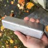
and then pull the bearing off.
I was then able to pull off the top pulley and remove the toothed belt.
Next job was to try and get into the gearbox, easier said than done Cheers, Paul. |
| Paul Major | 17/02/2014 22:22:50 |
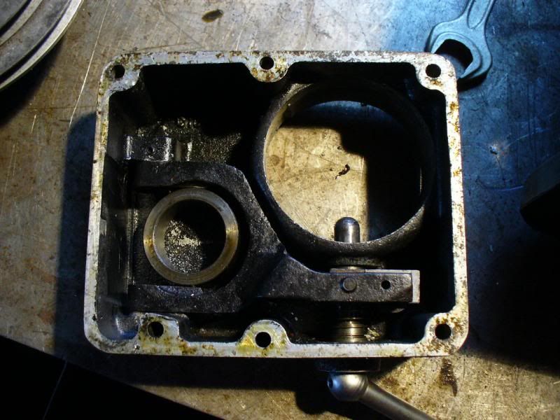
| 53 forum posts 13 photos | So, not sure if anyone is still reading this, can understand though - its probably not that rivetting just seeing something pulled apart Anyway, for posterities sake, started to dissassemble the gearbox which as well as transferring drive from the pulleys to the quill, also handles the backgear. First of removed the back gear lever, note spring that maintains the "detente" position on the lever,
The output shaft of the gearbox has a cog retained with a circlip. Circlip was removed and then a puller used on the gear revealing the woodruff key and rubber o-ring.
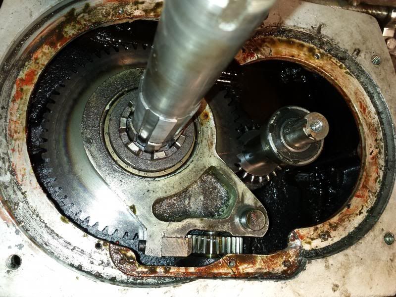
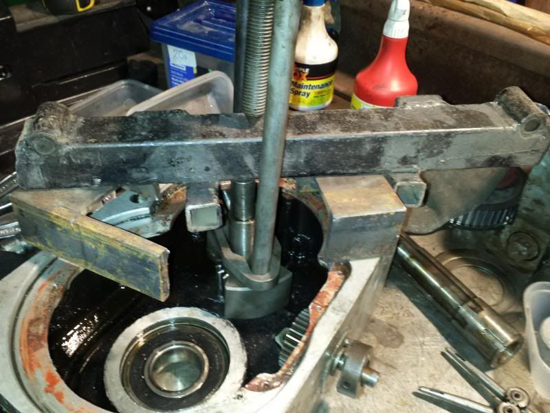
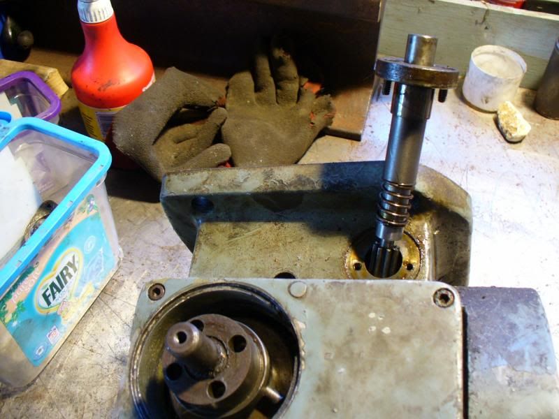
Flipped the 'box and attacked the top. The cover plate is held in by 4 screws but still wouldn't pop off. It turns out the backgear shaft has a bearing on the top end of the shaft which locates in the plate. To get the plate off you have to slide it off this bearing, but without anywhere to locate a puller its a bit of a job. Eventually levered it off.
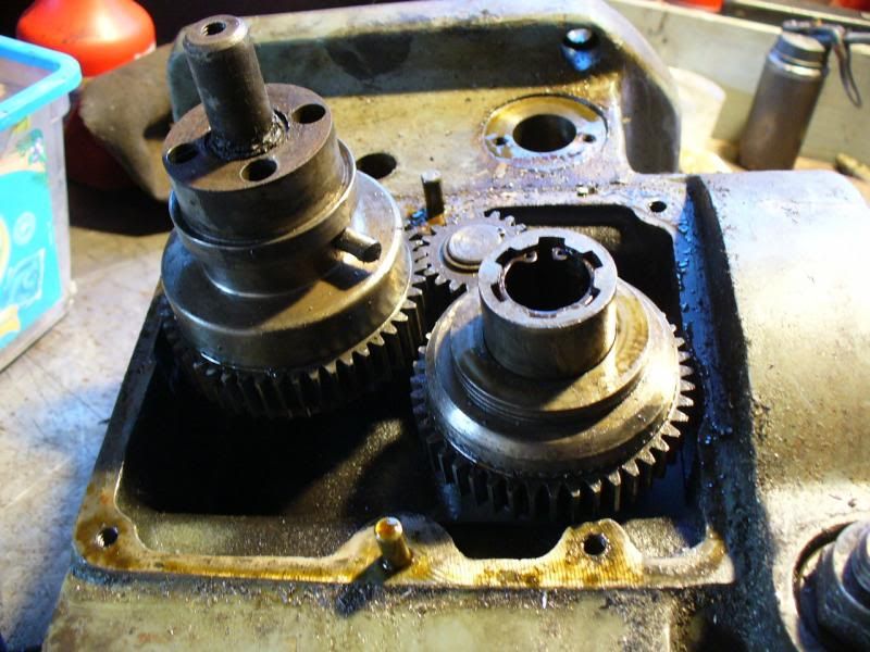
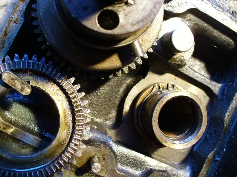
This is the insides of the gearbox, backgear shaft on the right and backgear selector hanging off the main shaft.
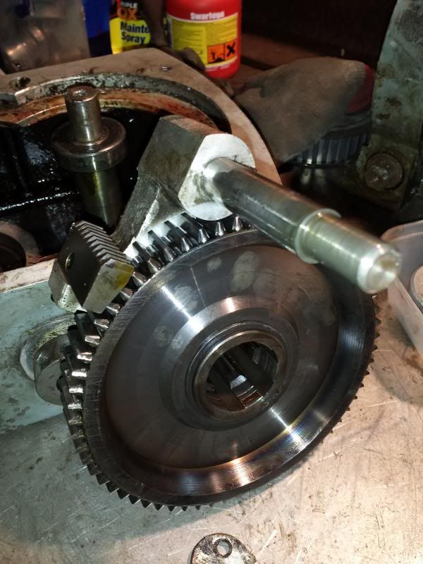
Backgear selector, wheel and clutch slid off the shaft
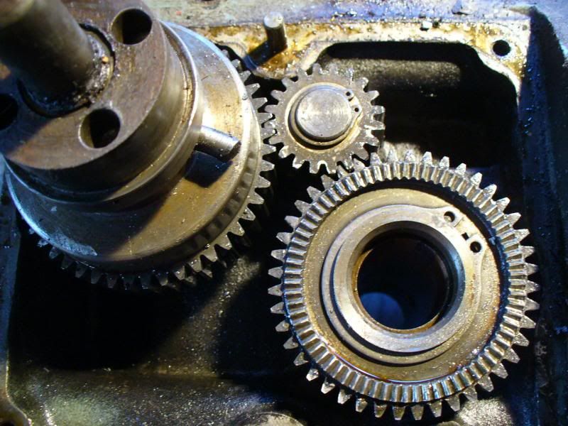
The shaft sits in a large bearing that sits in the bottom of the gearbox covered by a retaining plate on the underside and held in by the large circlip you can see in this picture.
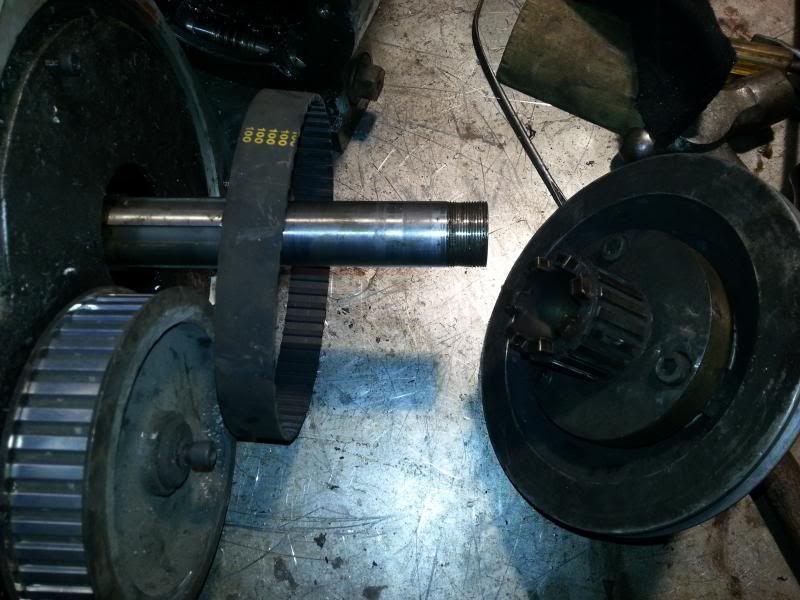
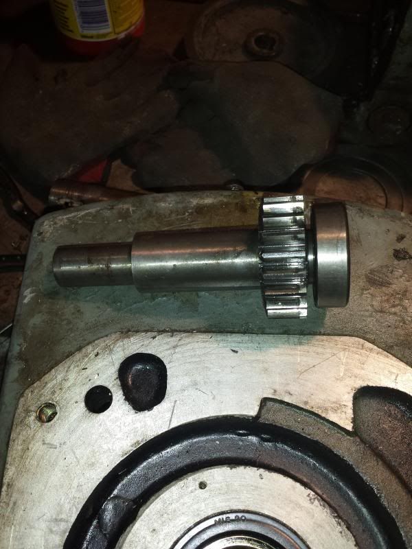
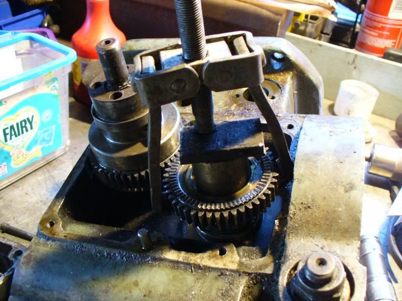
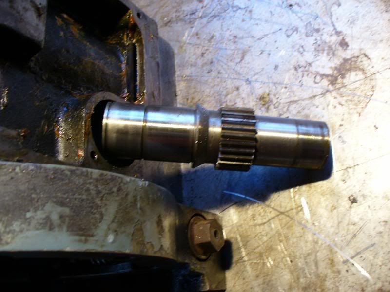
In the above picture you can also see a smaller circlip on the shaft itself, this is why the shaft cannot be withdrawn from the bottom of the gearbox and has to be removed via the procedure described above, i.e. from the top. With the main shaft out of the way I could then proceed to remove the backgear shaft. Some improvisation with another gear puller
and the shaft complete with lower bearing comes out.
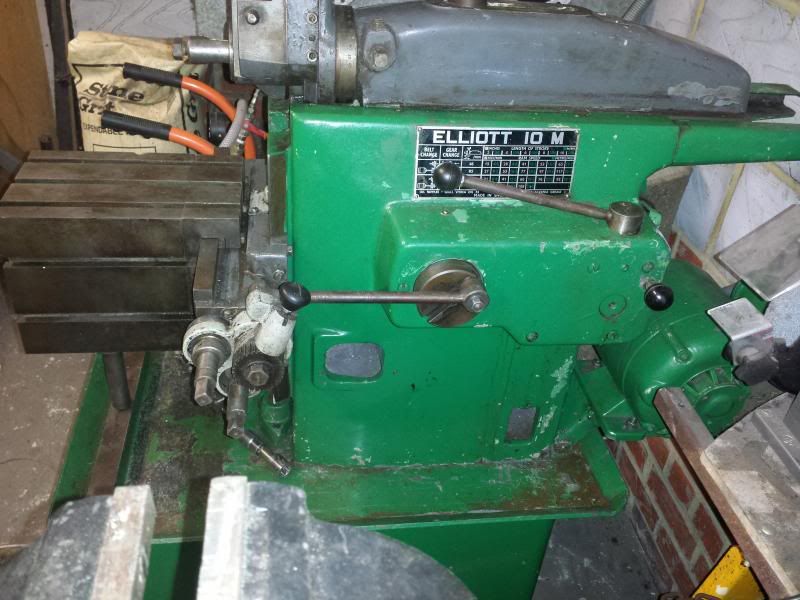
Next step, pressing out the main bearing and dropping the casing in the solvent tank, unfortunately I got a little bit distracted by purchasing and setting up this
Cheers, Paul.
Edited By Paul Major on 17/02/2014 22:26:41 |
| Russ B | 17/02/2014 22:27:41 |
| 635 forum posts 34 photos | (I'm still with you Paul |
| Paul Major | 18/02/2014 09:58:41 |
| 53 forum posts 13 photos | Thanks Russ |
| Harry Souders | 02/03/2014 09:41:36 |
| 5 forum posts | Hi Paul, I signed up just now to post in this thread. I was recently gifted an old Beaver PAL mill, and I've been trying to fix it up for the last month or so. My PAL is the smaller sibling of your VRBP - it's smaller overall, and only has (had) one powered axis. You're doing a great job so far, and I really appreciate all the detailed pictures and descriptions. I haven't gotten as far as you, but I have started the disassembly and inspection. The good news on my mill is that it doesn't seem like it's been used much. I see very little wear on leadscrews, gears, and other bearing surfaces. But, the bad news is that it looks like the mill was abused when it was used. Other than the usual cleaning and relubricating, I've discovered the following problems:
So... there are a number of problems to overcome, but it was a free mill so I can't really complain. Worst case scenario is that I'll learn a lot trying to fix it up. So far, I've taken most of the machine apart into its smaller subassemblies, drilled/reamed the worm shaft to install a 3/4" hex head, and I've straightened the bent X axis leadscrew. My progress has slowed over the last few weeks, as I'm waiting for a gear puller to remove the collar around my Y axis lead screw. If you have a chance, I'd love to see some shots of the spindle brake assembly, as I may end up fabricating that (it seems like parts and information are virtually nonexistent for the PAL mills). I'm loving the pictures of the mill disassembly - keep em coming. I wish I could help you, but it looks like you're farther than I am, and you already have all the lathes.co.uk info. While our machines aren't exactly the same, please let me know if there's anything I can help you with. Before I go, a couple questions... Do you find it strange that an English mill has all ANSI screw threads? Are your leadscrews also not hardened? Did your quill return spring also make a very unnerving unwinding noise when you pulled the clutch box? Do you have any ideas on how to retension that guy? Keep up the good work. |
| Daniel Robinson | 04/03/2014 17:11:21 |
 51 forum posts 23 photos | Hi Paul,
Dan
|
| Harry Souders | 07/03/2014 20:52:02 |
| 5 forum posts | Hey Dan... I don't suppose I could convince you to post a couple photos of the spindle brake assembly on your mill? Also, I'd love a copy of the user manual.... Any chance I could convince you? |
| Paul Major | 08/03/2014 08:53:06 |
| 53 forum posts 13 photos | Hey Harry/Dan some other Beavers - whoohoo I found very sporadic information on these when i started this journey despite many comments saying these mills were much better then the morw popular Bridgeport. Thats why I started this thread as I hoped it would attract/act as a resource for future Beaver owners. On the spindle brake, I will go take a few photos later today hopefully. I haven't actually checked what threads are on mine yet, doesn't matter when all younare doing is taking them apart Not sure if the leadscrews are hardened, how would you check? The user manual I have is about 55 pages, if your is 100 pages then it would be great if you could post up as it will increase the general,pool of info. Been busy withnwork last few weeks so haven't had a chance to progress the build but will try and add some more stuff this weekend. Cheers, Paul. |
| Paul Major | 08/03/2014 21:20:12 |
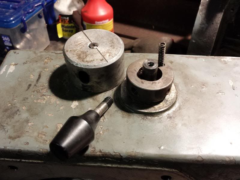
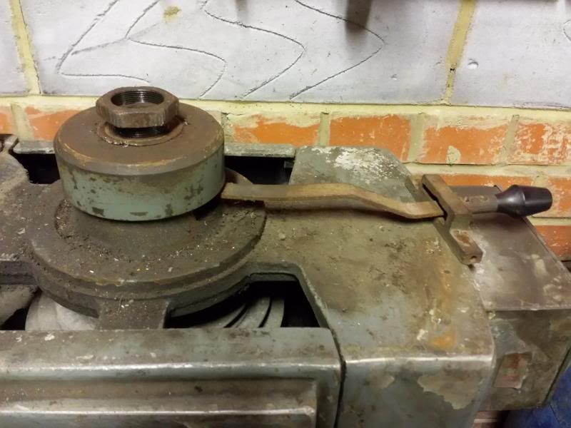
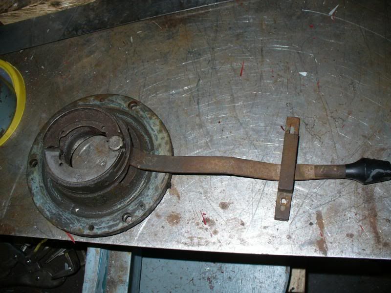
| 53 forum posts 13 photos | Hey Harry, info on spindle brake as promised. The brake sits on top of the pulley housing and acts on the top of the spindle.
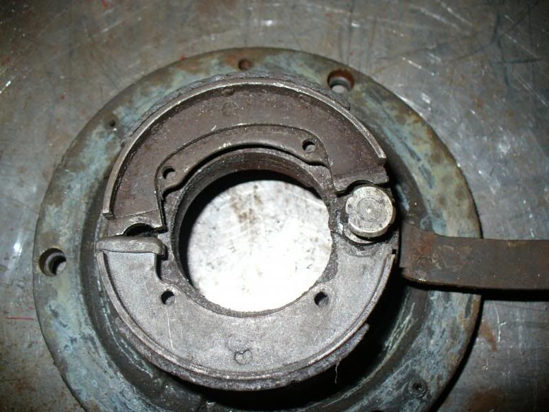
The lever operates a set of expanding shoes via a cam on the end of the lever
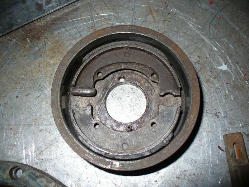
The brake shoes act on the inside of a drum
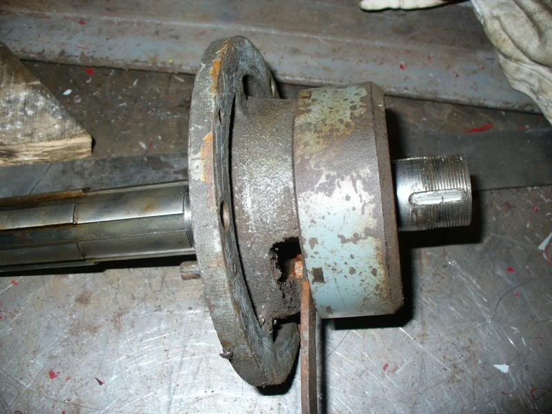
and when it is all assembled the drum sits kinda like this
So the drum is locked to the spindle and rotates and when the lever is pushed over the shoes expand onto the drum and hence brake the spindle. Hope that makes sense Cheers, Paul.
Edited By Paul Major on 08/03/2014 21:22:38 |
| Paul Major | 08/03/2014 21:31:16 |
| 53 forum posts 13 photos | Harry, couple of thoughts on re-reading your post. The quill spring didn't unwind significantly when removed. When I first removed the the quill I had to "unwind" the spring by holding the lever and gently rotating it. There is a warning in the manual to do this carefully as the tension on the spring could cause the lever to spin rapidly. Once I had the tensio off I did no further dissasembly on the spring mechanism as it looked like a clock spring that once undone would be a bugger to re-assemble! On removing the collar on the y axis, pay special attention to having removed the various cotter pins and grub screws, there are some detailed pics earlier in the thread. Mine had a couple of "hidden" grub screws, one under the mic locking ball bearing. Cheers, Paul.
|
| Paul Major | 08/03/2014 21:59:59 |
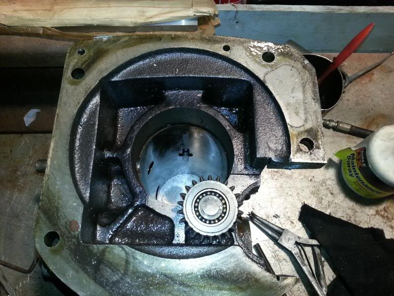
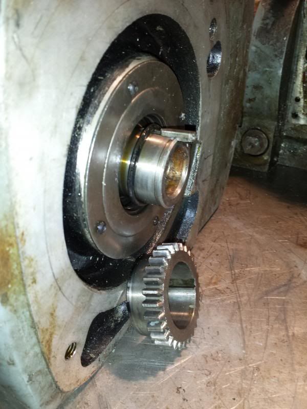
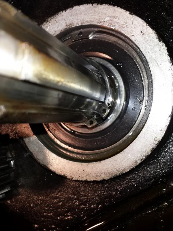
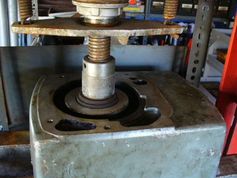
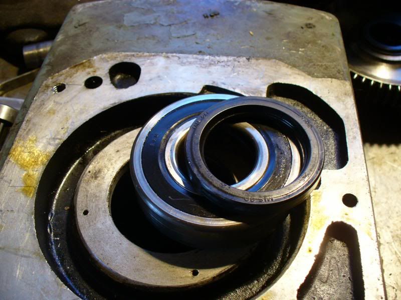
| 53 forum posts 13 photos | OK, back on track. Walked over the shed with the casing and pressend out the main bottom bearing.
There is a thin circular plate held on by 4 tiny screws that has to come off first. The bearing and seal is oriented like this.
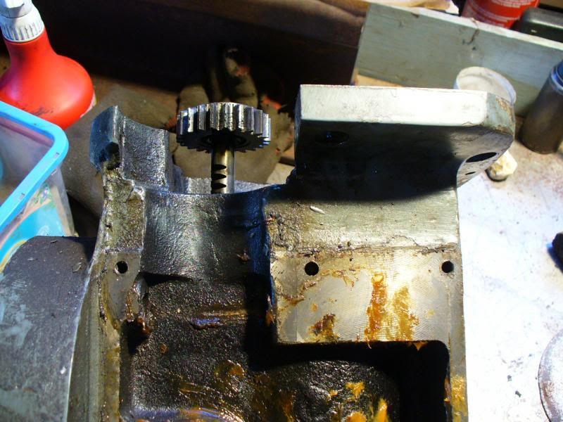
Then moved onto striping the bottom section of the head, starting with what I think is the idler gear.
Then the bushing that the pinion shaft sits in (IIRC
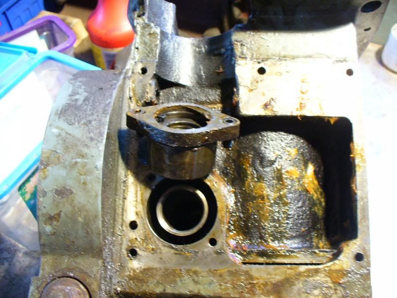
And the feed disengagement shaft/pinion
Removed the clutch box cover
Close up view showing location of circlips and pins
Removing the gear from the pinion shaft
Revealing another circlip on the shaft itself, hence why you wouldn't be able to remove the shaft without coming in from the clutch end.
Shaft removed
View inside the clutch cover showing how the clutch lever is located
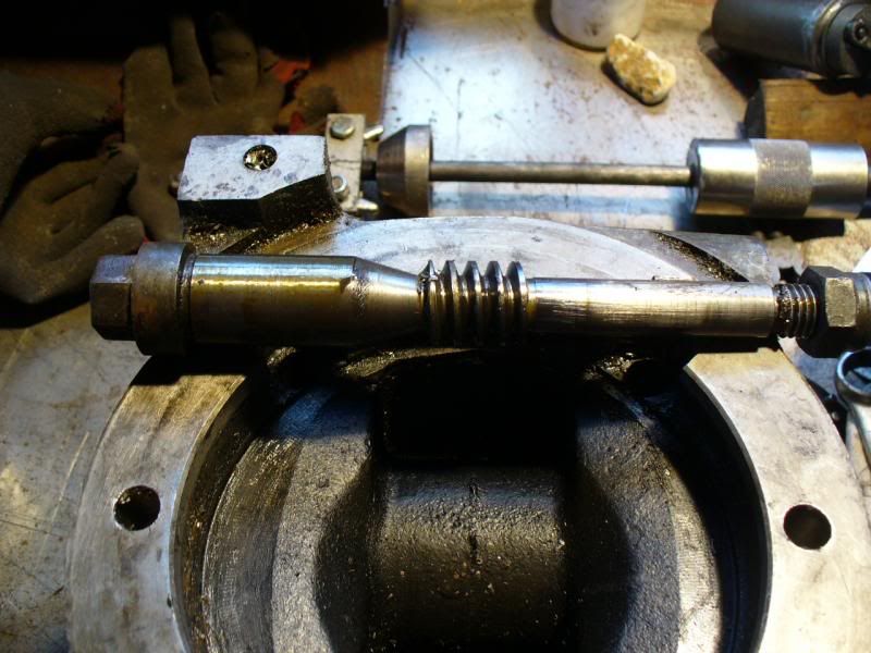
And finally, removed the worm shaft from the head/overarm
Thats the head pretty much stripped now. Might move onto cleaning, painting and stuff like that next so I can get some of this re-assembled before I loose any parts or forget how they go together Cheers, Paul. |
| Harry Souders | 09/03/2014 19:25:28 |
| 5 forum posts | Thanks for those brake pictures - it shouldn't be too difficult to fabricate a simple working brake. One question - do you have any idea what material the shoe is made of? I followed the quill removal instructions, but when I removed the clutch box, the quill spring still unwound. I guess I'll solve that problem when I reassemble it. An easy way to figure out if your lead screw is hardened is by running a file over it. If the screw cuts easily, it's probably not hardened. If the file doesn't cut easily, the screw is probably hardened. You can try a file on a couple different materials treated to different hardnesses and you'll get a feel for it. Lastly, my prints don't show the hidden set screw under the mic ball bearing, but that was definitely the issue. I should have taken a closer look at your writeup/pictures, but I got impatient and took a gear puller to the locking ring. The gear puller won the day, but it wasn't pretty. I can now see the hidden set screw, but I still can't push out that ball for the life of me. There must be a burr on the hole that's stopping the ball from coming out. Is there any chance I can get you to upload your documents? If you give me a couple days, I can probably scan/upload everything I have as well. |
| Paul Major | 09/03/2014 20:02:51 |
| 53 forum posts 13 photos | Hi Harry, material just looks like normal brake lining, probably softer than on a automotive brake, beyond that can't really tell. Any idea how to attached/upload stuff? Cheers, Paul. |
| Harry Souders | 09/03/2014 23:57:56 |
| 5 forum posts | Hmm, thanks. I'll probably end up using a bicycle brake pad for my brake. In the past I've used dropbox.com for transferring files to others. You can upload the file to dropbox, make it public, and just share the link. You don't need to use it as a backup service or install the desktop client like they want you to. |
| Harry Souders | 12/03/2014 06:22:03 |
| 5 forum posts | Here's all the documentation I have.... https://dl.dropboxusercontent.com/u/565517/Beaver%20Manual.pdf |
| Paul Major | 21/03/2014 22:45:31 |
| 53 forum posts 13 photos | Thanks Harry, here are links to two I have found, https://dl.dropboxusercontent.com/u/73721422/Beaver%20Mill%20Mk2.pdf https://dl.dropboxusercontent.com/u/73721422/beaver%20mk2.pdf Cheers, Paul. |
| Arnold Layne | 19/04/2014 11:06:34 |
| 1 forum posts | G'day gents, I've also got one of these old girls, all in one piece, mostly complete and reasonable nick for its age. Thanks for your efforts on this Paul, really appreciate the pics and detail. My plan is to clean up, do a VFD and get it running on single phase and see what needs fixing. After that I think I'll be doing at least a head rebuild, or maybe a full restoration. Heres a video of moving it in. http://youtu.be/l6f7hq3-7-Y
|
| Dillon Mulcahy | 11/06/2014 20:24:32 |
| 2 forum posts | Hey Paul, I am an engineering student and I am trying to get an old Beaver/Balding VBPR milling machine working again I was wondering If you had any more text on the machine that might be help full. Or any idea where I could get some spare parts for my machine I seem to be missing the cranks on the under belly that adjusts the tilling action on the mill. Thanks, Dillon |
| Robert James 3 | 29/07/2014 04:10:58 |
 18 forum posts | Hi Paul, Hello from across the pond, I'm Robert. I just set a VBRP ser 4769/2 in my shop. It's late here and it has been a long day but I look forward to reading your posts in the days ahead. Your posts will be very helpful to get my machine up and running in good shape. Thanks for your posts. Cheers! Robert
|
| Ady1 | 29/07/2014 10:13:08 |
 6137 forum posts 893 photos | not sure if anyone is still reading this A heck of a job. We are definitely watching |

Please login to post a reply.
Magazine Locator
Want the latest issue of Model Engineer or Model Engineers' Workshop? Use our magazine locator links to find your nearest stockist!
Sign up to our Newsletter
Sign up to our newsletter and get a free digital issue.
You can unsubscribe at anytime. View our privacy policy at www.mortons.co.uk/privacy
Latest Forum Posts
- *Oct 2023: FORUM MIGRATION TIMELINE*
05/10/2023 07:57:11 - Making ER11 collet chuck
05/10/2023 07:56:24 - What did you do today? 2023
05/10/2023 07:25:01 - Orrery
05/10/2023 06:00:41 - Wera hand-tools
05/10/2023 05:47:07 - New member
05/10/2023 04:40:11 - Problems with external pot on at1 vfd
05/10/2023 00:06:32 - Drain plug
04/10/2023 23:36:17 - digi phase converter for 10 machines.....
04/10/2023 23:13:48 - Winter Storage Of Locomotives
04/10/2023 21:02:11 - More Latest Posts...
- View All Topics
Support Our Partners


Shopping Partners
Subscription Offer

Latest "For Sale" Ads
- Reeves** - Rebuilt Royal Scot by Martin Evans
by John Broughton
£300.00 - BRITANNIA 5" GAUGE James Perrier
by Jon Seabright 1
£2,500.00 - Drill Grinder - for restoration
by Nigel Graham 2
£0.00 - WARCO WM18 MILLING MACHINE
by Alex Chudley
£1,200.00 - MYFORD SUPER 7 LATHE
by Alex Chudley
£2,000.00 - More "For Sale" Ads...
Latest "Wanted" Ads
- D1-3 backplate
by Michael Horley
Price Not Specified - fixed steady for a Colchester bantam mark1 800
by George Jervis
Price Not Specified - lbsc pansy
by JACK SIDEBOTHAM
Price Not Specified - Pratt Burnerd multifit chuck key.
by Tim Riome
Price Not Specified - BANDSAW BLADE WELDER
by HUGH
Price Not Specified - More "Wanted" Ads...
Get In Touch!
Do you want to contact the Model Engineer and Model Engineers' Workshop team?
You can contact us by phone, mail or email about the magazines including becoming a contributor, submitting reader's letters or making queries about articles. You can also get in touch about this website, advertising or other general issues.
Click THIS LINK for full contact details.
For subscription issues please see THIS LINK.
Digital Back Issues


Donate

 Register
 Log-in
Model Engineer Magazine
- Percival Marshall
- M.E. History
- LittleLEC
- M.E. Clock

ME Workshop
- An Adcock
- & Shipley
- Horizontal
- Mill

Subscribe Now
- Great savings
- Delivered to your door

Pre-order your copy!
- Delivered to your doorstep!
- Free UK delivery!
All Forum Topics > Manual machine tools > Restoring Beaver VBRP Mill