Forum sponsored by:

Making a large washer.
| Justin Thyme | 18/06/2023 11:09:01 |
| 72 forum posts | Posted by Hopper on 18/06/2023 10:52:04:
Posted by Justin Thyme on 18/06/2023 10:29:51:
Posted by Nicholas Farr on 18/06/2023 06:54:47:
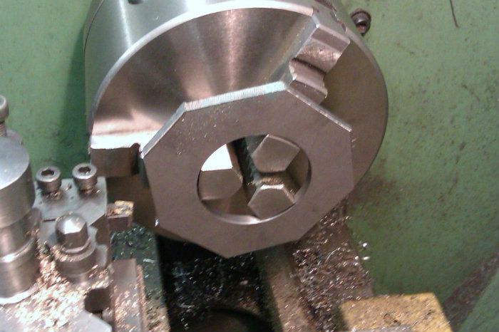
Hi Justin, don't you have a self centring three jaw chuck as shown in JasonB's second photo? Regards Nick. Edited By Nicholas Farr on 18/06/2023 06:58:06 Yes, but they don't take square bits, and even if I rounded the outside first they would not be big enough. If you look at Jason's pic, the three-jaw chuck is holding the job by the round hole in the middle. But you need to have the reverse jaws for your 3-jaw to do this.
Aye, but I needed to create the hole in the plate first, I was wishing to do this on the lathe. I had wanted an excuse to use the 4 jaw chuck. Now the hole is created (on the pillar drill) I can move on to the three jaw chuck to form the outer edge. (and yes I can soon get it into reasonable roundness with the angle-grinder before machining on the lathe As for downloading books, I got a box full of books along with the lathes, I find books hard going for some things. and was hoping to ask things not easily found in reference books on here. For instance, as I asked earlier, would removing the cross slide so as to do a job be a common practice. I didn't think it worth the time and effort for this job, but would that be something others would consider or would it be a big No No.
|
| Speedy Builder5 | 18/06/2023 11:28:17 |
| 2878 forum posts 248 photos | I think you meant topslide Justin. This would give you more rigidity of the cutting tool BUT you would need a special spacer to get the tool up to the centre line and your cross slide would need 'T' slots or a tapped hole to attach the tool post / spacer to. I have never bothered doing it. Bob |
| Hopper | 18/06/2023 11:30:48 |
 7881 forum posts 397 photos | Sorry, I thought you had made the hole and were now asking about the outside. Yes books can be hard going. But using a lathe is harder. So well worth the effort to sit around and browse a few of the former in order to make the latter easier. No it is not common to remove the cross slide because then you have nothing to mount the tool on and no way of controlling its depth of cut. But needs must and you could remove it for clearance if you needed to move the carriage under the large chuck so you could bring the tailstock up closer, if it would fit.
Edited By Hopper on 18/06/2023 11:31:49 Edited By Hopper on 18/06/2023 11:33:06 |
| Nicholas Farr | 18/06/2023 12:01:48 |
 3988 forum posts 1799 photos | Hi, I believe Justin only wanted to remove the cross-slide etc. to be able to move the carriage closer to the headstock, so that his tailstock would be able to get close enough to be able to reach with his hole saw to cut the virgin hole in the first place. However, if the cross-slide nut that can be seen in his photo doesn't come out easily, the carriage may still not pass below his chuck jaws without hitting it. Regards Nick. |
| not done it yet | 18/06/2023 12:51:49 |
| 7517 forum posts 20 photos | Posted by Nicholas Farr on 18/06/2023 12:01:48:
Hi, I believe Justin only wanted to remove the cross-slide etc. to be able to move the carriage closer to the headstock, so that his tailstock would be able to get close enough to be able to reach with his hole saw to cut the virgin hole in the first place. However, if the cross-slide nut that can be seen in his photo doesn't come out easily, the carriage may still not pass below his chuck jaws without hitting it. Regards Nick. How about removing tailstock, crank carriage to far end of bed and replace tailstock in front of carriage? If it will fit, that is. |
| Justin Thyme | 18/06/2023 13:15:52 |
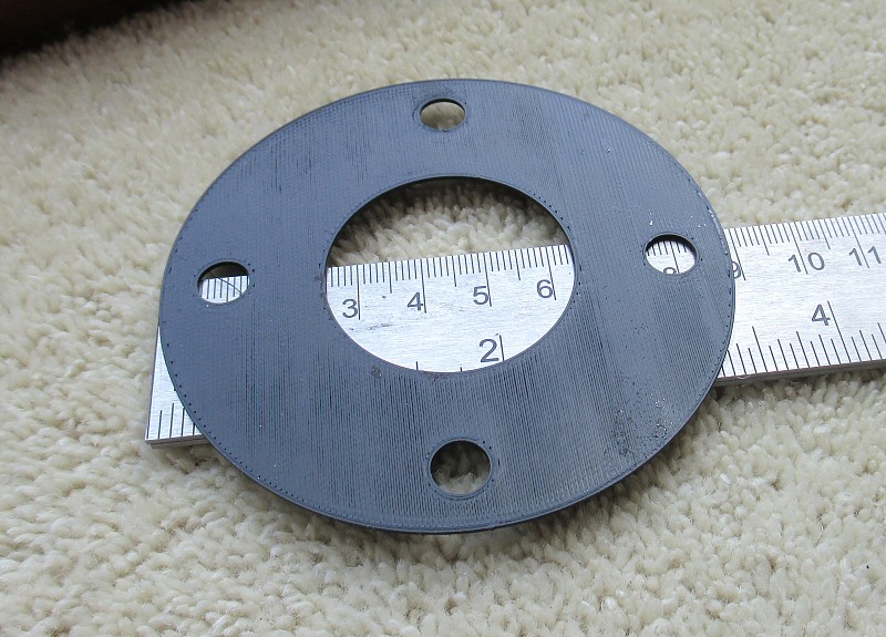
| 72 forum posts | Yes Nicholas, that is exactly what I was going to do, there would have been plenty room with the cross slide off, but I would have need to form a bit of plywood to protect the base from dirt, fillings etc, then would I need to readjust the gibs when reassembling, seemed like a lot of work , so did'nt bother. But it certainly could have been done if it was important, and this isn't. Anyway, moving on. I now have the two squarish plates with a 39mm hole in the middle. I now need to create an outer edge of 89mm dia concentric to the inner hole, and also 4 evenly spaced 8mm holes 35mm from the center.as per this 3d printed one The plan is to mount it into the chuck as per JasonB's earlier picture
My plan is to then score two circular marks, one with a dia of 70 and the other 89mm. The 70 mm dia line will allow me to mark out and drill the four 8mm holes and the 89 mm dia line will be a guide to cut and grind down to before remounting the piece in the chuck and precisely turning it down to 89mm But how do I accurately measure the two circles, how will I work out where the exact centre is? The smaller lathe has a digital readout, but how do I zero this? Should I start off with another piece of round bar and establish a zero point off that - or do I simply score a ine at say roughly 95mm, then if that measures manually at 94.7 would I use that as a ref and work from there. There is room on the chuck, so do I turn them at the same time ? should I hot melt glue them together, or may if there is enough room, drill the holes first and bolt them together. ?
|
| Nick Wheeler | 18/06/2023 13:31:23 |
| 1227 forum posts 101 photos | Were the four bolt holes in the original request? Because they change how you make the part: Start with a piece of stock big enough to create the piece Mark the centre of all three(centre hole, outside edge and PCD) circles. Draw the centre and outside edges with dividers. Mark out the PCD. Drill the PCD Bolt the piece to a (sacrificial)faceplate using the PCD, and ensure it runs true to the centre mark Machine the inner and outer edges.
You make several pieces by bolting them to the faceplate at the same time
Edited By Nick Wheeler on 18/06/2023 13:32:39 |
| JasonB | 18/06/2023 13:33:45 |
 25215 forum posts 3105 photos 1 articles | Put a light mark in one place with a turning tool held in the toolpost, rotate chuck 180deg and put another light mark. Measure the distance between the two and adjust and repeat until you get the 70mm one. Wind out the cross slide by 9.5mm and than you can mark the 89mm line Alternative is to measure 25mm out from the edge of the hole to get your 89mm mark and then wind in 9.5mm to do the 70mm |
| not done it yet | 18/06/2023 15:18:26 |
| 7517 forum posts 20 photos | Could any of this be done on a lathe or milling machine ? It could all have been done on a milling machine. Including the holes. What is the required precision of this part? Like, would clearance holes be adequate? If you have a mill (and neither rotary table nor dro), someone could easily obtain the coordinates for the holes from their own dro. Altenatively, using self-help, finding the coordinatesfor those holes is a fairly straight-forward operation. |
| noel shelley | 18/06/2023 15:44:31 |
| 2308 forum posts 33 photos | The dear old Zeus book will give coordinates ! Noel. |
| JasonB | 18/06/2023 16:14:37 |
25215 forum posts 3105 photos 1 articles | If you need to get a Zeuz book out for that 4 hole pattern, use a rotary table or use a DRO's PCD there is not much hope for you 70/2 should be possible im most peoples heads and then just move that amount in/out/left /right Edited By JasonB on 18/06/2023 16:15:45 |
| DiogenesII | 18/06/2023 16:22:30 |
| 859 forum posts 268 photos | ..of only it was a square with corners.. |
| Justin Thyme | 19/06/2023 21:15:25 |
| 72 forum posts | Posted by Nick Wheeler on 18/06/2023 13:31:23:
Were the four bolt holes in the original request? Because they change how you make the part: Start with a piece of stock big enough to create the piece Mark the centre of all three(centre hole, outside edge and PCD) circles. Draw the centre and outside edges with dividers. Mark out the PCD. Drill the PCD Bolt the piece to a (sacrificial)faceplate using the PCD, and ensure it runs true to the centre mark Machine the inner and outer edges.
You make several pieces by bolting them to the faceplate at the same time
Ooop's, yes I seem to have omitted that important spec.. I did mark out all the three circles before I started. The problem arose when I used the pillar drill to bore the centre hole out with the hole saw, the pillar drill is so unconcentric it managed to get the not very round hole in the wrong place. See my first image, you can see the scored line .
Never mind, I managed to mount it on the milling machine, and with an edge finder on the inside of the hole I worked out where the centre would be. from here it was very straight forward to get the holes drilled accurately (within a few thou, I quite surprised myself) I was then able to score a line to where the outer edge will be. From there I have hacksawed and angle grinded it down to a roundish shape. I'm going to have a good think about how I will lathe this down to its 89mm dia - it's non-roundness is a concern. What speed should I start with? When doing such things turning wood I will keep the speed very low until it gets fairly round. Will I use the same tactic on steel ? I did spin it and felt 100-150 rpm seemed OK, not sure though I could get a 3rd bolt in to hold the plated together, should I bother, it seems very secure |
| Nigel Graham 2 | 19/06/2023 23:31:55 |
| 3293 forum posts 112 photos | Hole saws are not intended to be precise. Typically they are building tools used for pipe and conduit ways, drilling water-tanks for their fittings and the like. Nevertheless they are a valid way to rough out the work provided you select a size that leaves sufficient machining allowance, and I use them fairly frequently for that. You say your pillar-drill (or bench-drill? They do differ!) is not concentric. Are you sure? A hole saw can give that impression depending on its type, even though its holder's pilot-drill acts as a guide. You can't hope to use a hole saw without that pilot, so it won't enlarge an existing hole without some preparatory work. . Looking back at other's suggestions, I would start with an octagon or "more-agon", but round the corners off a bit first with a file or angle-grinder, as turning down from sharp corners can be a bit fraught. . Trepanning can work well provided you can hold the work on both sides of the cut. This is based on how I machined large rings from 1/2" thick steel plate: If the work has holes in it, as here, I would drill them and use them to hold the plate to a faceplate with intervening spacers or a scrap of plywood. I would also drill holes in the outer (off-cut) area for further holding. This is so the cut completes without great lumps of steel with razor-sharp burrs suddenly breaking free and possibly causing havoc The tool shape needs careful thought if it is not to bind. My approach is to start the cut well on the scrap side, in a little way, withdraw the tool and offset it slightly to widen the cut. Take it slow and steady, alternating the trench diameter to give clearance. Finally unscrew the off-cut from the faceplate and finish-turn the diameter. . Can this piece be made on a rotary-table and vertical mill? Yes. a ring of bolt-holes concentric with the finished diameters is basic rotary-table work, if the number of holes is a factor of 360º. It normally is! You can mill the entire component in this way. Set out and drill some holding-screw holes in the off-cut areas (leave room for the heads!) to secure the plate to the table by Tee-nuts. Use a sacrificial plate or spacers as with the lathe faceplate. Centre the rotary-table under the spindle and set the axis (usually the long one) dial or the DRO if so fitted to 0. Turn the RT to 0º. Fit the work-piece and spacer(s) to the table. Now you can drill the component bolt-holes and trepan the ring out by using a slot-drill, with due regard to cut depth for cutter diameter. It's a slow and rather tedious process with large diameters, on a manually-driven rotary-table, but effective. . Incidentally, if you ever need set out a ring of 4 equi-spaced holes by co-ordinates, or relate a square's diagonal to a diameter, the diameter of a square's circumscribing circle is 1.414 X Diagonal. (Square root of 2 - derived from Pythagoras' Theorem.) Other polygons and their formulae are available! Edited By Nigel Graham 2 on 19/06/2023 23:34:01 |
| Hopper | 20/06/2023 01:53:18 |
7881 forum posts 397 photos | About 100 RPM should do you for that diameter with a HSS toolbit. Could be twice that with carbide, but with the way you are holding the job I would stick at 100 RPM and take it easy. It should clean that nice round shape up pretty easily. It is when you leave it square or even octagonal and you get a harsh interrupted cut that things get interesting. The two bolts should be sufficient. |
| Justin Thyme | 20/06/2023 06:37:44 |
| 72 forum posts | with the thought that carbide is brittle and can shatter. Would it be safer to at least start this 'interrupted' cut with a HSS bit ? Since I'm going to do this job now, I will use a HSS bit (if they fit the tool holder) , but be interested in your thoughts if this is a valid concern |
| JasonB | 20/06/2023 06:57:27 |
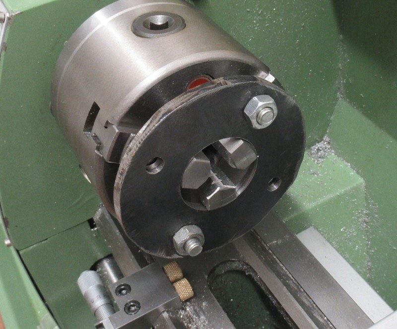
25215 forum posts 3105 photos 1 articles | If you are using carbide just wind in gently with not too deep a cut, plenty of insert milling cutters that don't suffer from interuppted cuts. That's a carbide lathe tool in my photo, it will also cope better with the mill scale you have on your metal 250-300rpm with carbide which will also put your variable speed lathe's motor in a happier place Edited By JasonB on 20/06/2023 07:38:59 |
Please login to post a reply.
Magazine Locator
Want the latest issue of Model Engineer or Model Engineers' Workshop? Use our magazine locator links to find your nearest stockist!
Sign up to our Newsletter
Sign up to our newsletter and get a free digital issue.
You can unsubscribe at anytime. View our privacy policy at www.mortons.co.uk/privacy
Latest Forum Posts
- hemingway ball turner
04/07/2025 14:40:26 - *Oct 2023: FORUM MIGRATION TIMELINE*
05/10/2023 07:57:11 - Making ER11 collet chuck
05/10/2023 07:56:24 - What did you do today? 2023
05/10/2023 07:25:01 - Orrery
05/10/2023 06:00:41 - Wera hand-tools
05/10/2023 05:47:07 - New member
05/10/2023 04:40:11 - Problems with external pot on at1 vfd
05/10/2023 00:06:32 - Drain plug
04/10/2023 23:36:17 - digi phase converter for 10 machines.....
04/10/2023 23:13:48 - More Latest Posts...
- View All Topics
Support Our Partners


Shopping Partners
Subscription Offer

Latest "For Sale" Ads
- Reeves** - Rebuilt Royal Scot by Martin Evans
by John Broughton
£300.00 - BRITANNIA 5" GAUGE James Perrier
by Jon Seabright 1
£2,500.00 - Drill Grinder - for restoration
by Nigel Graham 2
£0.00 - WARCO WM18 MILLING MACHINE
by Alex Chudley
£1,200.00 - MYFORD SUPER 7 LATHE
by Alex Chudley
£2,000.00 - More "For Sale" Ads...
Latest "Wanted" Ads
- D1-3 backplate
by Michael Horley
Price Not Specified - fixed steady for a Colchester bantam mark1 800
by George Jervis
Price Not Specified - lbsc pansy
by JACK SIDEBOTHAM
Price Not Specified - Pratt Burnerd multifit chuck key.
by Tim Riome
Price Not Specified - BANDSAW BLADE WELDER
by HUGH
Price Not Specified - More "Wanted" Ads...
Get In Touch!
Do you want to contact the Model Engineer and Model Engineers' Workshop team?
You can contact us by phone, mail or email about the magazines including becoming a contributor, submitting reader's letters or making queries about articles. You can also get in touch about this website, advertising or other general issues.
Click THIS LINK for full contact details.
For subscription issues please see THIS LINK.
Digital Back Issues


Donate

 Register
 Log-in
Model Engineer Magazine
- Percival Marshall
- M.E. History
- LittleLEC
- M.E. Clock

ME Workshop
- An Adcock
- & Shipley
- Horizontal
- Mill

Subscribe Now
- Great savings
- Delivered to your door

Pre-order your copy!
- Delivered to your doorstep!
- Free UK delivery!
All Forum Topics > General Questions > Making a large washer.