Forum sponsored by:

VFD. XSY AT4 220v 1phase to 380v 3phase advice sort
| James Walker | 02/08/2020 20:45:55 |
| 11 forum posts 1 photos | I always took P00 as being the max V that the unit could output. The reason being that P02 and P04 have a cap of either 220V or 380V which I believe is determined by P00. Anyway I have my P00 set at 380V and it is fed a 220-230V supply. Also if you have settings that you cannot change you need to input the default "0" password into P09. i.e. jusrt go into param update mode, go to input mode on P09 and "set" the value to 0. This should unlock everything. Did for me.
Cheers, James.
|
| Andrew Johnston | 02/08/2020 20:53:37 |
 7061 forum posts 719 photos | I can't see anywhere in the listing, or on the specification plate, where it says the output voltage is 380VAC phase to phase? Andrew |
| Andrew Firman | 02/08/2020 21:14:08 |
| 37 forum posts 18 photos | Posted by Andrew Firman on 02/08/2020 20:12:59:
Greg, Although the "manual" does not explain I believe P000 is the input voltage which should be left at 220V. That's what mine are set at and both 380 star configured motors run fine.
Sorry Greg, Senior moment! James is correct . P000 on mine is set at 380V.. |
| Andrew Firman | 02/08/2020 21:30:14 |
| 37 forum posts 18 photos | Posted by Andrew Johnston on 02/08/2020 20:53:37:
I can't see anywhere in the listing, or on the specification plate, where it says the output voltage is 380VAC phase to phase? Andrew Andrew, In the manual it states AT4 output phase to phase is 380v
|
| Andrew Johnston | 03/08/2020 08:15:59 |
7061 forum posts 719 photos | Thanks; it's not that common to have single phase in and 380V 3-phase out. I'm surprised the listings don't make more of it. Andrew |
| OneManEngineering | 03/08/2020 09:52:41 |
| 33 forum posts 48 photos | Posted by James Walker on 02/08/2020 20:45:55:
I always took P00 as being the max V that the unit could output. The reason being that P02 and P04 have a cap of either 220V or 380V which I believe is determined by P00. Anyway I have my P00 set at 380V and it is fed a 220-230V supply. Also if you have settings that you cannot change you need to input the default "0" password into P09. i.e. jusrt go into param update mode, go to input mode on P09 and "set" the value to 0. This should unlock everything. Did for me.
Cheers, James.
Ill try to enter the password and see if I can change P000. This thing spins my motor up nicely, make no mistake about it, but unable to measure RPM. BTW, my motor is in DELTA!. |
| john fletcher 1 | 03/08/2020 09:53:08 |
| 893 forum posts | I have been reading with interest the threads relating to the the XSY inverter. Would a reader please tell me the make of the XSY 2.2 Kw inverter, could it be a Huanyang ? John |
| OneManEngineering | 03/08/2020 09:54:09 |
| 33 forum posts 48 photos | Posted by Andrew Firman on 02/08/2020 21:14:08:
Posted by Andrew Firman on 02/08/2020 20:12:59:
Sorry Greg, Senior moment! James is correct . P000 on mine is set at 380V.. You're forgiven! I am getting there too. |
| OneManEngineering | 03/08/2020 09:56:40 |
| 33 forum posts 48 photos | Posted by john fletcher 1 on 03/08/2020 09:53:08:
I have been reading with interest the threads relating to the the XSY inverter. Would a reader please tell me the make of the XSY 2.2 Kw inverter, could it be a Huanyang ? John It certainly isn't, but it looks to me that its a sort of copy. It works. I can recommend, but you need to learn the new Chin-glish language. At least my manual is written in that :D
|
| Emgee | 03/08/2020 10:19:24 |
| 2610 forum posts 312 photos | Posted by john fletcher 1 on 03/08/2020 09:53:08:
I have been reading with interest the threads relating to the the XSY inverter. Would a reader please tell me the make of the XSY 2.2 Kw inverter, could it be a Huanyang ? John Could be here Emgee Deleted Edited By JasonB on 05/08/2020 06:52:38 |
| Robert Atkinson 2 | 03/08/2020 11:43:44 |
 1891 forum posts 37 photos | Posted by Andrew Firman on 24/05/2020 14:49:47:
Many thanks Martin, The PE terminal is quite easy to see when the board is removed from the case. There is a red wire that connects the terminal and the main board and then through the brass board supports to the fins
The pot is new with a measured resistance of 10.7K . It seems ok but I don’t have any others to swap it with - awaiting a couple from China. I have set P10 and P11 to 2. I’ve checked the voltage between fins and a mains supply earth connected to the PE terminal and now get a reading of 3v ac down from 85v. Don’t know why it’s not zero but I guess one can live with 3v
That protective earth (PE) connection looks pretty scary. Red insulation and a straght bit of solder tinned wire under a PCB mounting screw, The wire clearly is not large enough to carry fault currents on a system fused for 3kW (13A). Solder tinned wires (tin plated is different) should never be used under screw or crimp connections, The solder cold flows under pressure and a bad joint results. Used to be common with mains leads before pre-fitted plugs to find the leads solder tinned but this was found to be the cause of loose connetions and over-heaing plugs. Red wire on a PE is a technical breach of the acceptable standards. These things are a liability. As a minimum they must be inside a suitable enclosure. The user is legally responsible for making sure the installation is compliant with all relevant safety and EMI/EMC standards. In practice this does not happen. Robert G8RPI. |
| OneManEngineering | 05/08/2020 00:43:27 |
| 33 forum posts 48 photos | Posted by James Walker on 02/08/2020 20:45:55:
I always took P00 as being the max V that the unit could output. The reason being that P02 and P04 have a cap of either 220V or 380V which I believe is determined by P00. Anyway I have my P00 set at 380V and it is fed a 220-230V supply. Also if you have settings that you cannot change you need to input the default "0" password into P09. i.e. jusrt go into param update mode, go to input mode on P09 and "set" the value to 0. This should unlock everything. Did for me.
Cheers, James.
Well, I have tried! Still don’t work. I set P002 to 190V but P000 still don’t go over 220V.
HOW DO YOU DO A FACTORY RESET ON THIS THING?
Greg
|
| Andrew Firman | 05/08/2020 10:38:03 |
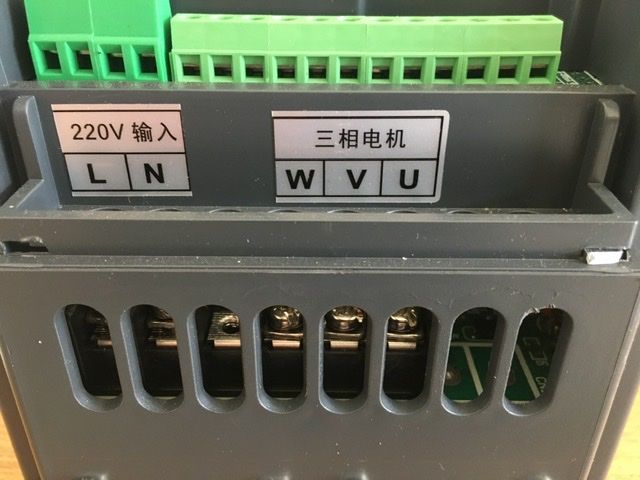
| 37 forum posts 18 photos | Greg, I’ve not done or found out how to do a factory reset, however a couple of other posters seem to have done so. I presume your terminals and labelling look identical to those in my photos. There seems to be a difference between an AT1 (220v) and an AT4 (380v). I did once try to up load a file with all my parameter settings but couldn’t because it apparently had too many characters. I’ll try again in the next couple of days. |
| Martin of Wick | 05/08/2020 11:50:30 |
| 258 forum posts 11 photos | Greg, If it is truly an AT4, you should have no trouble setting P0 to default 380v and usually they arrive correctly programmed anyway. Check the boards as Andrew suggests. Usually AT1 have the earth on the incomer side and NOT on the control side as with the AT4 - but there could be variants. I strongly suggest before you resort to resetting, that you fully work your way through the manual and parameters and understand the important ones that relate to your intended operation. A full reset may result in some very strange parameter conditions and unintended consequences (in my experience). Set up on the bench and go through all of the significant parameters as stored in the device and write them down. try to check and change the ones you want again and check the running. Try to understand the manual - most of the info is there, just not in a helpful form. If you really want to do a full reset have regard to Parameter P77 and the associated reset condition 54321. but take heed, you are likely to get some unexpected consequences and may need to re enter some of the parameters you wrote down from interrogating the registers. In my case I was able to restore most functionality except for the ramp times which now requires dividing the required Hz/s by10! Take very, very great care with these AT4 devices, they output very high peak voltages at high currents.
|
| OneManEngineering | 08/08/2020 19:42:31 |
| 33 forum posts 48 photos | Guys, thank you ever so much for y'all input. I went back to the vendor and they asked me to go and have it fixed somewhere near me and they shall bear the costs. That means one thing I guess... yep its a sort of mutant between 220V and 380V. dang! Hence why it doesn't do what yours does. So I am now getting a new one, hopefully a working one this time.
Greg |
| OneManEngineering | 08/08/2020 19:46:27 |
| 33 forum posts 48 photos | Posted by Robert Atkinson 2 on 03/08/2020 11:43:44:
That protective earth (PE) connection looks pretty scary. Red insulation and a straght bit of solder tinned wire under a PCB mounting screw, The wire clearly is not large enough to carry fault currents on a system fused for 3kW (13A). Solder tinned wires (tin plated is different) should never be used under screw or crimp connections, The solder cold flows under pressure and a bad joint results. Used to be common with mains leads before pre-fitted plugs to find the leads solder tinned but this was found to be the cause of loose connetions and over-heaing plugs. Red wire on a PE is a technical breach of the acceptable standards.
These things are a liability. As a minimum they must be inside a suitable enclosure. The user is legally responsible for making sure the installation is compliant with all relevant safety and EMI/EMC standards. In practice this does not happen. Robert G8RPI. Hey Rob, could you pls have a look at this: What do you suggest what to do? I kind of figured I ground my motor to the VFD's PE, but you kinda made me change my mind. (This is the only ref point that I could call GND.)
What shall I Do? Thanks, Greg |
| Bob Worsley | 11/08/2020 11:14:09 |
| 146 forum posts | Fascinating. From the photos all I can see are two large electrolytic caps, are there any more? To boost the incoming 220V to 440V needs two caps, then you also need at least one smoothing cap on the 400V DC rail. Can't read the voltage rating of the two obvious caps. With extreme care, is it possible to measure the voltage on the two caps? If they are the boost caps then each will have about 240V or so, if the DC rail cap then it will have 440V or so. If there isn't a 400V DC rail inside the VFD then not going to get 380V AC out.
|
| Peter Bell | 11/08/2020 13:02:50 |
| 399 forum posts 167 photos | Not sure if its exactly the same as the one I looked inside but that only had the voltage doublers caps so I assumed they were also the smoothing caps. It also had a small module to reduce the surge switch on when the cap were initially charging and the rail voltage was 660v dc.. Peter |
| john fletcher 1 | 11/08/2020 13:25:30 |
| 893 forum posts | After all the discussion and theory to go with it, wouldn't be easier to dig out the motor Star point and bring out the 3 end to the terminal box , then buy a inverter with 3 Ph and 220 out. I remember some excellent picture on here together with an explanation of what to maybe a year or so ago. Its not so difficult to do, once you have the motor apart.. John |
| SillyOldDuffer | 11/08/2020 13:51:06 |
| 10668 forum posts 2415 photos | Posted by Bob Worsley on 11/08/2020 11:14:09:
... From the photos all I can see are two large electrolytic caps, are there any more? To boost the incoming 220V to 440V needs two caps, then you also need at least one smoothing cap on the 400V DC rail. ...If there isn't a 400V DC rail inside the VFD then not going to get 380V AC out.
True, but no-one said how that high voltage rail should be produced. In my youth, we said the transformer was too small if you could lift a power supply! Because everything worked at 50Hz, large components were essential. Voltage doublers and other compromises were common, despite their disadvantages. Modern designers have more choice. For example mains can be converted to any AC frequency he chooses. Then volts can be stepped up with a high-frequency transformer because at typical carrier frequencies (2kHz to 20kHz) they're tiny. Mice compared with the elephants needed to work efficiently at 50Hz. Difficult to generalise about the merits of a VFD without studying it's circuit diagram, component ratings and cooling arrangements. I'd not fret about buying a high-voltage VFD if I needed one, especially now they're affordable. Dave
|


Please login to post a reply.
Magazine Locator
Want the latest issue of Model Engineer or Model Engineers' Workshop? Use our magazine locator links to find your nearest stockist!
Sign up to our Newsletter
Sign up to our newsletter and get a free digital issue.
You can unsubscribe at anytime. View our privacy policy at www.mortons.co.uk/privacy
Latest Forum Posts
- *Oct 2023: FORUM MIGRATION TIMELINE*
05/10/2023 07:57:11 - Making ER11 collet chuck
05/10/2023 07:56:24 - What did you do today? 2023
05/10/2023 07:25:01 - Orrery
05/10/2023 06:00:41 - Wera hand-tools
05/10/2023 05:47:07 - New member
05/10/2023 04:40:11 - Problems with external pot on at1 vfd
05/10/2023 00:06:32 - Drain plug
04/10/2023 23:36:17 - digi phase converter for 10 machines.....
04/10/2023 23:13:48 - Winter Storage Of Locomotives
04/10/2023 21:02:11 - More Latest Posts...
- View All Topics
Support Our Partners


Shopping Partners
Subscription Offer

Latest "For Sale" Ads
- Reeves** - Rebuilt Royal Scot by Martin Evans
by John Broughton
£300.00 - BRITANNIA 5" GAUGE James Perrier
by Jon Seabright 1
£2,500.00 - Drill Grinder - for restoration
by Nigel Graham 2
£0.00 - WARCO WM18 MILLING MACHINE
by Alex Chudley
£1,200.00 - MYFORD SUPER 7 LATHE
by Alex Chudley
£2,000.00 - More "For Sale" Ads...
Latest "Wanted" Ads
- D1-3 backplate
by Michael Horley
Price Not Specified - fixed steady for a Colchester bantam mark1 800
by George Jervis
Price Not Specified - lbsc pansy
by JACK SIDEBOTHAM
Price Not Specified - Pratt Burnerd multifit chuck key.
by Tim Riome
Price Not Specified - BANDSAW BLADE WELDER
by HUGH
Price Not Specified - More "Wanted" Ads...
Get In Touch!
Do you want to contact the Model Engineer and Model Engineers' Workshop team?
You can contact us by phone, mail or email about the magazines including becoming a contributor, submitting reader's letters or making queries about articles. You can also get in touch about this website, advertising or other general issues.
Click THIS LINK for full contact details.
For subscription issues please see THIS LINK.
Digital Back Issues


Donate

 Register
 Log-in
Model Engineer Magazine
- Percival Marshall
- M.E. History
- LittleLEC
- M.E. Clock

ME Workshop
- An Adcock
- & Shipley
- Horizontal
- Mill

Subscribe Now
- Great savings
- Delivered to your door

Pre-order your copy!
- Delivered to your doorstep!
- Free UK delivery!
All Forum Topics > General Questions > VFD. XSY AT4 220v 1phase to 380v 3phase advice sort