Forum sponsored by:

Building a GOTO Mount
| Ajohnw | 24/11/2015 23:51:17 |
| 3631 forum posts 160 photos | It up to you Neil not me. As for instance looking at ab IR golden oldy More expensive but I would be thinking in terms of something like this. Max switching frequency about 3khz - way way to high, drive series resistance 4 to 10K. There has been some debate in astro circles about using low side drivers when these are available. In TO220 they start at 5amps as shown here In surface mount, some are easy to hand solder, there will be more available and some pcb copper can be used as a heatsink. There is info about on their web site about that, often in the data sheets but I have only ever needed to look at that on straight ordinary mosfets. John -
|
| Neil Wyatt | 25/11/2015 09:46:30 |
 19226 forum posts 749 photos 86 articles | Ignore that. I made some wrong assumptions. |
| Ian P | 25/11/2015 09:54:11 |
 2747 forum posts 123 photos | Posted by Ian Phillips on 23/11/2015 21:35:25:
Neil Curiosity has got the better of me, is the purpose of JP4 or the switch so that you can test the PSU? IanP Bumping my own post, but what does the switch do? |
| Neil Wyatt | 25/11/2015 09:57:44 |
19226 forum posts 749 photos 86 articles | I'm sure 100R will be fine, any more and all it will do is slow down the switching. I don't want the dew heaters to be more than a few watts, so perhaps I should just use bipolar transistors. BC107 should be up to the job Neil |
| Ajohnw | 25/11/2015 10:09:30 |
| 3631 forum posts 160 photos |
Meant to add - a board like that with 3 stepper drivers and a couple of switched output may be of interest in other areas. John - Edited By John W1 on 25/11/2015 10:10:58 |
| Ian S C | 25/11/2015 10:20:41 |
 7468 forum posts 230 photos | I can get you an OC70 from my junk box. Ian S C |
| Ajohnw | 25/11/2015 10:39:35 |
| 3631 forum posts 160 photos | Posted by Ian S C on 25/11/2015 10:20:41:
I can get you an OC70 from my junk box. Ian S C Great idea as they have lower saturation voltages. Certain ZTX's are way way better than BC017's as an alternative. One of them can be used as a high side switch too - however ........................ I have a few germanium bits about too. They came with an Xmas present when I was around 8 or 9. My electronic set. Had an electric one the year before but motors/dynamos and shocking coils etc get boring after a while. All of that one has unfortunately gone, most of the other too. I never thought of it as a career but strangely finished up doing rather a lot of it at times. John - Edited By John W1 on 25/11/2015 10:44:52 |
| Neil Wyatt | 25/11/2015 11:50:40 |
19226 forum posts 749 photos 86 articles | Posted by Ian Phillips on 25/11/2015 09:54:11:
Posted by Ian Phillips on 23/11/2015 21:35:25:
Neil Curiosity has got the better of me, is the purpose of JP4 or the switch so that you can test the PSU? IanP Bumping my own post, but what does the switch do? Er.. turn it on and off? N. |
| Neil Wyatt | 25/11/2015 11:52:58 |
19226 forum posts 749 photos 86 articles | I'd point anyone wanting to do this at the RAMPS shield, rather than copying mine - this one will need bespoke software, while the Ramps will be arduino compatible. Neil |
| jason udall | 25/11/2015 12:04:16 |
| 2032 forum posts 41 photos | Having championed the ramps previously. .. The ramps isn't " arduino" compatible any more than than any circuit anything compatible. The pin out fits a particular arduino model The ramps basically acts to breakout these pins and add some hardware interface. ( sockets for stepper drivers...three 5 amp fets... Five rc servo ports...and more. And other bits/bobs.. If you are expecting a shield with handy-dandy library ..sorry |
| Neil Wyatt | 25/11/2015 12:38:03 |
19226 forum posts 749 photos 86 articles | What I mean is RAMPS a shield for the Arduino mega (which sounds like compatible to me) and all the libraries for use with the Mega will be available as well as the Arduino IDE. I'll be programming mine in AVR assembler from scratch using studio 6.2. I wouldn't recommend that to others - its the path I choose because it is one of my interests. If the end product is of use to others I'll be willing to share it, but I'm not going to build in extra complexity because someone else might want to use it for something else in the future. Neil P.S. if you think hanging a FET of a port pin is dodgy, what about this from AVRfreaks:
|
| jason udall | 25/11/2015 14:11:21 |
| 2032 forum posts 41 photos | Neil..and what I mean is that the ramps isn't exclusively arduino...conveniently yes but not to be overlooked if using pi. Pic.or otherwise.. |
| Ian P | 25/11/2015 15:22:48 |
2747 forum posts 123 photos | Posted by Neil Wyatt on 25/11/2015 11:50:40:
Posted by Ian Phillips on 25/11/2015 09:54:11:
Posted by Ian Phillips on 23/11/2015 21:35:25:
Neil Curiosity has got the better of me, is the purpose of JP4 or the switch so that you can test the PSU? IanP Bumping my own post, but what does the switch do? Er.. turn it on and off? N. So does the PSU sense that its output is being shorted so it shuts down? Ian P |
| Ajohnw | 25/11/2015 15:43:05 |
| 3631 forum posts 160 photos | Freaks is the right thing to have on the end of the name. It's interesting to put a current sense on the supply on a circuit like that but few people have anything suitable - high frequency hall effect oscilloscope probe as both mosfets will be on for short periods as they are switched. They have sort of done something about the problems that is likely to cause on the supply almost certainly adding more parts than if the drive had been done correctly. 90nSec rise times are good at generating RFI especially with long lengths of wire on them. No need so why switch that quickly unless it's needed. The actual rise times might turn out faster that that. I'd hope that the data sheets have pulse thermal resistance info otherwise guess. The absolute maximum rating of the i/o pins on the processor is 40ma however the max for the chip is 200ma. They point out that these aren't what might be called real absolute ratings as long term use might damage the device or cause premature failure and later reduce them to 50% as far as the pins are concerned. Often on electronic items spec's are given in regions that they are expected to work in. As far as output is concerned that's 3ma but on this sort of part that can be exceeded providing the totals are looked at. The i/o conditions that the device can stand are given in condition 3&4 on page 317 of the full data. Essentially 100ma per port by the look of it and 20ma per pin - they don't mention the chip limit when driving which is likely to be 100ma max in practical terms with near 10 running the processor. The reason for putting something in the way when driving mosfets is the capacitance in them. It's possible for the processor pin to get volts forced onto it back through the mosfet. The ports do have clamp diodes but it looks like they are for ESD protection only as they don't specify a max current through them. Processors turn into thyristors if the port input voltage range is exceeded. A puff of smoke, a nasty smell comes out and a small hole appears in the package. Not terribly likely in this case but it can happen. Pull down resistor can help a bit even the usual 20k because it may happen when they are inputs. Looks like high side drivers ideally need pull downs as well. I'd have thought that they would build them into the chip as no one wants to add more bits. It's annoying. Lots of things need them to define what happens during reset and before the post is set to the correct state. John - |
| Neil Wyatt | 25/11/2015 16:10:46 |
19226 forum posts 749 photos 86 articles | Posted by Ian Phillips on 25/11/2015 15:22:48:
Posted by Neil Wyatt on 25/11/2015 11:50:40:
Posted by Ian Phillips on 25/11/2015 09:54:11:
Posted by Ian Phillips on 23/11/2015 21:35:25:
Neil Curiosity has got the better of me, is the purpose of JP4 or the switch so that you can test the PSU? IanP Bumping my own post, but what does the switch do? Er.. turn it on and off? N. So does the PSU sense that its output is being shorted so it shuts down? Ian P You are making this complicated. Two wires from the pads go to a switch, and two more wires go from the switch to a battery.
Neil |
| jason udall | 25/11/2015 16:29:29 |
| 2032 forum posts 41 photos | Looking at that from avr freaks.. One...its in effect a dimmer. It even sniffs the ac...so the sw could switch (both fets on) at zero crossing... Bit confused over the IR sensors with switch to short out but ho hum |
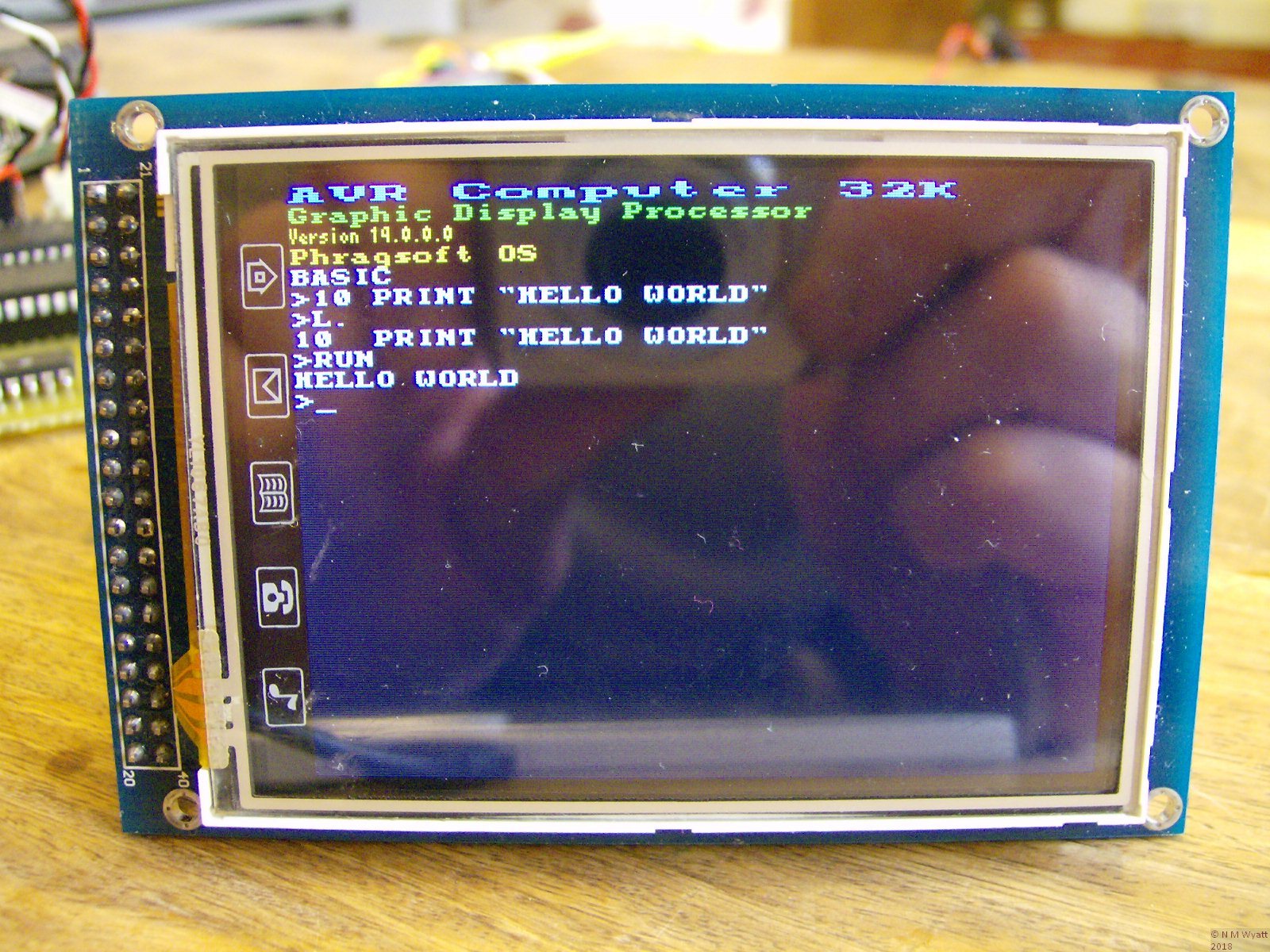
| Neil Wyatt | 25/11/2015 16:39:24 |
19226 forum posts 749 photos 86 articles | Whatever the datasheets say, in practice AVRs are pretty bombproof. I think I've blown one up so far. They can do quite surprising things... This:
Plus this:
Makes this (actually this is an earlier version, that ran out of flash for the interpreter and more esoteric display driver functions):
Which does this (amongst other things):
Later version isn't very pretty... but it is a work in progress.
|
| Ian P | 25/11/2015 16:39:28 |
2747 forum posts 123 photos | Neil Not trying to make it complicated, just that it looked to me as if the two wires went to the poles of a switch. If it had said 'From Switch' or 'from PSU' I probably would have twigged. As the power supply is not shown and you (sensibly) use the same symbol for all the points connected to 12v I thought 'JP4' was used for either a switch or a jumper. Presumably the normal on/off switch would be on the input side of the PSU but putting the connector on the board gives you the choice later. Now, studying your PDF in greater detail I realise that all your connectors have the JP prefix. Ian P
|
| Ajohnw | 25/11/2015 17:47:47 |
| 3631 forum posts 160 photos | Posted by jason udall on 25/11/2015 16:29:29:
Looking at that from avr freaks.. One...its in effect a dimmer. It even sniffs the ac...so the sw could switch (both fets on) at zero crossing... Bit confused over the IR sensors with switch to short out but ho hum LOL I missed that aspect and something else about it too. How the load is connected.
Unused pins on them have the usual suggestions. Activate the internal pull up resistors or better still in some circumstances use external pull ups and pull down but direct connect to a rail is discouraged. If a board was ever available I would be happy providing that any spare pins could,be used if needed. Atmel do have a zero crossing application note that shows that the input pin diodes can be used as clamps via high value resistors. A rather low current as I suspected. We have had mains spikes round here that have blown dimmers and bulbs. Not sure how it would cope with that. They can be in the Kv range, more than one of them at times. MOV's have killed that problem. John - |
| Neil Wyatt | 25/11/2015 19:13:11 |
19226 forum posts 749 photos 86 articles | Posted by Ian Phillips on 25/11/2015 16:39:28:
Now, studying your PDF in greater detail I realise that all your connectors have the JP prefix. To be fair on me, its really just a working diagram to generate the PCB, so I'm happy to flaunt conventions or use the wrong part with the right footprint, for example. If I use a 'pin header' to get a series of pads at 0.1" spacing, it calls it a 'jumper'. Often I wire direct into them, especially for power leads. It took me a while to understand 'nets', if you use these instead of a wire to join up power pins etc. then you don't need to physically join them up on the circuit diagram. This is what I have done with +5, +12 and GND. The board is a right dog's dinner at the moment. |


Please login to post a reply.
Magazine Locator
Want the latest issue of Model Engineer or Model Engineers' Workshop? Use our magazine locator links to find your nearest stockist!
Sign up to our Newsletter
Sign up to our newsletter and get a free digital issue.
You can unsubscribe at anytime. View our privacy policy at www.mortons.co.uk/privacy
Latest Forum Posts
- hemingway ball turner
04/07/2025 14:40:26 - *Oct 2023: FORUM MIGRATION TIMELINE*
05/10/2023 07:57:11 - Making ER11 collet chuck
05/10/2023 07:56:24 - What did you do today? 2023
05/10/2023 07:25:01 - Orrery
05/10/2023 06:00:41 - Wera hand-tools
05/10/2023 05:47:07 - New member
05/10/2023 04:40:11 - Problems with external pot on at1 vfd
05/10/2023 00:06:32 - Drain plug
04/10/2023 23:36:17 - digi phase converter for 10 machines.....
04/10/2023 23:13:48 - More Latest Posts...
- View All Topics
Support Our Partners


Shopping Partners
Subscription Offer

Latest "For Sale" Ads
- Reeves** - Rebuilt Royal Scot by Martin Evans
by John Broughton
£300.00 - BRITANNIA 5" GAUGE James Perrier
by Jon Seabright 1
£2,500.00 - Drill Grinder - for restoration
by Nigel Graham 2
£0.00 - WARCO WM18 MILLING MACHINE
by Alex Chudley
£1,200.00 - MYFORD SUPER 7 LATHE
by Alex Chudley
£2,000.00 - More "For Sale" Ads...
Latest "Wanted" Ads
- D1-3 backplate
by Michael Horley
Price Not Specified - fixed steady for a Colchester bantam mark1 800
by George Jervis
Price Not Specified - lbsc pansy
by JACK SIDEBOTHAM
Price Not Specified - Pratt Burnerd multifit chuck key.
by Tim Riome
Price Not Specified - BANDSAW BLADE WELDER
by HUGH
Price Not Specified - More "Wanted" Ads...
Get In Touch!
Do you want to contact the Model Engineer and Model Engineers' Workshop team?
You can contact us by phone, mail or email about the magazines including becoming a contributor, submitting reader's letters or making queries about articles. You can also get in touch about this website, advertising or other general issues.
Click THIS LINK for full contact details.
For subscription issues please see THIS LINK.
Digital Back Issues


Donate

 Register
 Log-in
Model Engineer Magazine
- Percival Marshall
- M.E. History
- LittleLEC
- M.E. Clock

ME Workshop
- An Adcock
- & Shipley
- Horizontal
- Mill

Subscribe Now
- Great savings
- Delivered to your door

Pre-order your copy!
- Delivered to your doorstep!
- Free UK delivery!
All Forum Topics > Related Hobbies including Vehicle Restoration > Building a GOTO Mount