Forum sponsored by:

Rotary Laser centre finder
An unusual design centre finder for the mill
| FMES | 25/01/2014 23:11:15 |
| 608 forum posts 2 photos | Why do you need to have the offset angle?I could understand it if you were trying to get a depth or vertical displacement. Personally I use one of these **LINK** which fits in a collet or chuck, could be used rotating or not.
|
| Michael Gilligan | 25/01/2014 23:19:44 |
 23121 forum posts 1360 photos | Posted by Lofty76 on 25/01/2014 23:11:15:
Why do you need to have the offset angle? . Did you watch the video that John linked in his original post? Angle produces cone ... Cone makes useful patterns on various shaped workpieces. MichaelG. |
| John Stevenson | 25/01/2014 23:33:47 |
 5068 forum posts 3 photos | Posted by Ian Phillips on 25/01/2014 23:08:52:
No it doesn't matter but what I was trying to say is that I can see they are not in line but how do we know which one is correct?
Ian Simples, the one that is not in the centre in incorrect. It's on top of a round bar so central is central. if it were a flat bar then bets are off as it could be anywhere. |
| Michael Gilligan | 25/01/2014 23:45:57 |
23121 forum posts 1360 photos | Posted by MICHAEL WILLIAMS on 25/01/2014 23:34:14:
Problem is though no matter how good a device is you are still trying to line up on a centre pop or such like making super accuracy a pointless exercise .
Far better to apply ingenuity to making laser devices which can locate tooling relative to absolute datums on machine or work . What about laser equivalent of toolmakers buttons ? . For those thinking along these lines, the Ickey Ball is [literally] "a very good place to start". It should work rather well in conjunction with the aforementioned Rotary device. MichaelG. Edited By Michael Gilligan on 25/01/2014 23:52:21 |
| John Stevenson | 26/01/2014 00:23:46 |
5068 forum posts 3 photos | Not bad £106 to £138 a pop, think I'll order a dozen to play with
OK joking, its the link that's important
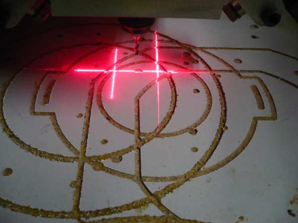
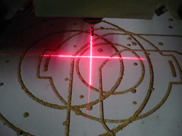
Found those crossed line laser pics.
And lined up at 100mm above the work.
Bombs away
Edited By John Stevenson on 26/01/2014 00:24:13 |
| Michael Gilligan | 26/01/2014 00:42:15 |
23121 forum posts 1360 photos | Posted by John Stevenson on 26/01/2014 00:23:46:
Not bad £106 to £138 a pop, think I'll order a dozen to play with OK joking, its the link that's important . Yes, the price is unfortunate ... Mine was amongst the goodies in a nice wooden Toolmaker's cabinet that I bought years ago. ... Can't afford another though. Question 1: How much should they cost ? ... given that the asterisked dimensions are good to a tenth of a thou' Question 2: Does anyone have a bright idea how to make something along the same lines, that's good enough to be useful, and cheap enough to buy or make ? MichaelG. . P.S. The DamBusters rig looks excellent !!
MichaelG. |
| John McNamara | 26/01/2014 05:37:47 |
 1377 forum posts 133 photos | Hi All I think Michael Williams has sparked an Idea with toolmakers buttons. He got me thinking and I sketched up using AutoCAD how a 12mm wide by 15mm high button might show up with the cone of the laser beam directed upon it. For the test I have displaced the button .025mm to the right therefore it is off the axis of the machine by that amount I have angled the rotating beam 10 degrees from vertical. As the image below shows the line of the intersecting laser beam does slope as would be expected.
However not a lot. Thinking on this It made it clear that what was needed was that the beam and should strike the button at a smaller angle. This would amplify any spindle alignment error. An angled button would be better but that would be very difficult to place on the work, I therefore drew another button the same size but with a chamfer on it leaving the base parallel. This would make it easy to place the button in the normal way. while providing a surface for the laser to strike. As the following illustration shows the angle of the striking is now much greater as expected The cone displays the error very graphically over 5mm out of level. (note the displacement was not changed at .025mm) There would be little problem in correcting the .025mm error to maybe a quarter of that by levelling the cone.
AutoCAD was even kind enough to make the edge of the cone fuzzy as it would show to a lesser extent with the laser. Reviewing Dan Gelbart's video confirms this the image was quite clear when he applied the laser to the side of a bar to centre drill it. He mentions 50 micrometre accuracy for his tool that's a fraction less than .002 inches. I guess he believes that is the minimum accuracy for all measurements possible with this tool? Cone on Cone I believe we can do a considerably better. Marking out to .001 inches is possible on a good day but we must add to that the error left by the spotting drill starting off axis... And that was on a good day. Toolmakers buttons.... There are a couple more images in my album Regards Edited By John McNamara on 26/01/2014 06:07:23 |
| John McNamara | 26/01/2014 07:12:56 |
1377 forum posts 133 photos | Clarification of the following sentence in the above post, it is not Clear. Marking out to .001 inches is possible on a good day but we must add to that the error left by the spotting drill starting off axis... And that was on a good day. Should read Marking out (with a centre punch) to within .001 inches accuracy is possible on a good day but we must add to that the error left by the spotting drill starting off axis... And that was on a good day. The laser pointer can do a lot better than marking out... particularly when focussed on a toolmakers button with a chamfer. Regards
|
| Michael Gilligan | 26/01/2014 09:05:21 |
23121 forum posts 1360 photos | John, Thanks for the AutoCAD demonstration of concept. ... Very useful diagrams. MichaelG. . Edit: If it's not too much trouble; would you be so kind as to try an Ickey Ball in that sketch. I feel sure that this would be a superb way to set an "origin" datum point. Edited By Michael Gilligan on 26/01/2014 09:26:07 |
| Michael Gilligan | 26/01/2014 10:05:46 |
23121 forum posts 1360 photos | I've just found this brief autobiographical note by our hero. MichaelG . Edit: ... the forum editing software won't let me insert the link. It keeps insisting that I must "Paste from Word" Edit: ... the software seems to be paranoid, but I have found a way http://spie.org/ x42147 sorry, you will need to concatenate those lines, then add [.][x][m][l] ... with the brackets removed
Edited By Michael Gilligan on 26/01/2014 10:11:29 and many more times !! Edited By Michael Gilligan on 26/01/2014 10:39:01 |
| Ian P | 26/01/2014 10:28:21 |
 2747 forum posts 123 photos | Michael Has your last post about not being able to insert a link been deleted? I have had 7 attempts to post a link, all have failed even when I follow the instructions.
Ian |
| John McNamara | 26/01/2014 10:33:29 |
1377 forum posts 133 photos | Hi Michael The Ball target as requested.... it would also be a lot easier to make on the lathe. Just bore the hole, turn and lap the cylinder to exact size then and chamfer to form the cone and carefully part off. With care it should be pretty accurate, Not hardened but good enough for most work.
Regards |
| Ian P | 26/01/2014 10:34:00 |
2747 forum posts 123 photos | Michael Oh! I see its reappeared, together with all your edits. I was trying to give the same link, it seems the forum software has been changed, but Katy has not informed us. Ian P
|
| Michael Gilligan | 26/01/2014 10:44:52 |
23121 forum posts 1360 photos | John, Many thanks for the prompt, and cost-saving (!), illustration. MichaelG. |
| Michael Gilligan | 26/01/2014 10:49:25 |
23121 forum posts 1360 photos | Posted by Ian Phillips on 26/01/2014 10:34:00:
Michael Oh! I see its reappeared, together with all your edits. I was trying to give the same link, it seems the forum software has been changed, but Katy has not informed us. Ian P . Ian, It looks like the forum software is probably blocking direct links to anything ending in "exemel". MichaelG. |
| Michael Horner | 26/01/2014 11:04:44 |
| 229 forum posts 63 photos | Hi If you have to drill a hole in the job, couldn't you use a ball bearing? You'd probably want to to stain it black otherwise you might get bejazzeld! Cheers Michael. |
| John McNamara | 26/01/2014 11:41:30 |
1377 forum posts 133 photos | Hi Michael H For referencing a workpiece A ball is not as good as a cone for centring with a Laser as shown above. However If you drilled and reamed a master hole in a piece that was to be removed and replaced in the mill several times you could place the cone target in the hole and reference the machine to that point each time. Or screw the reference cone to the workpiece for the duration of the job. making it absolutely rigid, Various referencing targets could be made with different size spigots for different size holes, Toolmakers buttons (with a chamfer for the laser not shown in the link below) just need a flat base to be screwed onto the work. **LINK** Regards |
| Ady1 | 26/01/2014 11:49:48 |
 6137 forum posts 893 photos | Family braincell moment: If the laser is slightly adjustable, ie with a grubscrew then the drill can spot a point and the laser can be adjusted to the spot point Then the laser is spot on for the cutting point of that particular drill/mill Occasionally I come across a drill which "isn't quite right" but I don't have a replacement It may be the drill itself or the way the chuck holds it Edited By Ady1 on 26/01/2014 11:52:36 |
| John McNamara | 26/01/2014 12:02:22 |
1377 forum posts 133 photos | Hi Ady1 I think you have missed the beauty of this design it is inherently accurate working on first principals. The point rotates around the axis of the spindle bearings, All you need to do to change the circle or spot size is raise or lower the quill. The only adjustment needed is to align the laser so it crosses the axis to get the smallest spot size, but even if you don't do that it will still show a perfectly centred circle. Regards Edited By John McNamara on 26/01/2014 12:04:17 |
| Michael Gilligan | 26/01/2014 14:10:34 |
23121 forum posts 1360 photos | Posted by John McNamara on 26/01/2014 10:33:29:
Hi Michael The Ball target as requested.... . John, Sorry to labour this, but I've just realised that you have the light shining on, or near, the equator ... I wonder if it would give more useful results if incident somewhere near the "Tropic of Cancer". [?] MichaelG. |


Please login to post a reply.
Magazine Locator
Want the latest issue of Model Engineer or Model Engineers' Workshop? Use our magazine locator links to find your nearest stockist!
Sign up to our Newsletter
Sign up to our newsletter and get a free digital issue.
You can unsubscribe at anytime. View our privacy policy at www.mortons.co.uk/privacy
Latest Forum Posts
- hemingway ball turner
04/07/2025 14:40:26 - *Oct 2023: FORUM MIGRATION TIMELINE*
05/10/2023 07:57:11 - Making ER11 collet chuck
05/10/2023 07:56:24 - What did you do today? 2023
05/10/2023 07:25:01 - Orrery
05/10/2023 06:00:41 - Wera hand-tools
05/10/2023 05:47:07 - New member
05/10/2023 04:40:11 - Problems with external pot on at1 vfd
05/10/2023 00:06:32 - Drain plug
04/10/2023 23:36:17 - digi phase converter for 10 machines.....
04/10/2023 23:13:48 - More Latest Posts...
- View All Topics
Support Our Partners


Shopping Partners
Subscription Offer

Latest "For Sale" Ads
- Reeves** - Rebuilt Royal Scot by Martin Evans
by John Broughton
£300.00 - BRITANNIA 5" GAUGE James Perrier
by Jon Seabright 1
£2,500.00 - Drill Grinder - for restoration
by Nigel Graham 2
£0.00 - WARCO WM18 MILLING MACHINE
by Alex Chudley
£1,200.00 - MYFORD SUPER 7 LATHE
by Alex Chudley
£2,000.00 - More "For Sale" Ads...
Latest "Wanted" Ads
- D1-3 backplate
by Michael Horley
Price Not Specified - fixed steady for a Colchester bantam mark1 800
by George Jervis
Price Not Specified - lbsc pansy
by JACK SIDEBOTHAM
Price Not Specified - Pratt Burnerd multifit chuck key.
by Tim Riome
Price Not Specified - BANDSAW BLADE WELDER
by HUGH
Price Not Specified - More "Wanted" Ads...
Get In Touch!
Do you want to contact the Model Engineer and Model Engineers' Workshop team?
You can contact us by phone, mail or email about the magazines including becoming a contributor, submitting reader's letters or making queries about articles. You can also get in touch about this website, advertising or other general issues.
Click THIS LINK for full contact details.
For subscription issues please see THIS LINK.
Digital Back Issues


Donate

 Register
 Log-in
Model Engineer Magazine
- Percival Marshall
- M.E. History
- LittleLEC
- M.E. Clock

ME Workshop
- An Adcock
- & Shipley
- Horizontal
- Mill

Subscribe Now
- Great savings
- Delivered to your door

Pre-order your copy!
- Delivered to your doorstep!
- Free UK delivery!
All Forum Topics > Workshop Tools and Tooling > Rotary Laser centre finder