Forum sponsored by:

steam turbine and generator
| Versaboss | 13/01/2011 22:18:06 |
| 512 forum posts 77 photos | Posted by Richard Parsons on 13/01/2011 07:39:36:
C. Balance - Prof Chaddock wrote to me and said that he had to get the centre of rotation within 0.000002” the centre of mass. He did this with two razor edges some ‘bluetak’ and a small scraper.
Hmm, had to misuse the internet again.... If my calculator and old brain are not completely off, the stated distance above is around 100 atom diameters (of the larger kinds, but his turbine was not built from hydrogen I think). Quite impressive with a bit of bluetak. Unfortunately we can't ask Mr. Chaddock how he measured it. I formally apologize If I should be wrong... Greetings, Hansrudolf |
| Richard Parsons | 14/01/2011 06:31:11 |
 645 forum posts 33 photos |
Keith I sort of knew about Prof Chaddock’s work. I had a long chat at MEX when it was at Wembley. This lead to a long correspondence between, us mainly about nozzles. I had an idea that the low output could have been due to shockwaves developing in the throats of the nozzles. In the end (with some help from some Hitile designers –well the Rapier missiles did not often miss). After lots of calculations on my PC I found the steam flow was almost certainly sub sonic. So it was ‘Hay Ho’ and back to the drawing board. Paul are you talking about ‘pea bulbs’ –which do not care if it is AC or DC-. |
| Richard Parsons | 14/01/2011 06:59:25 |
645 forum posts 33 photos |
Hansrudolph sorry I missed your posting How it was done (I used the same technique). You spun the rotor on a pair of knife edged (mine were Razor blades). You found the heavy side and put a smear of blutak on the opposite side of the wheel to make it heavy (er). With a scalpel scrape some off the heavy side of the rotor. If the blutak was heavy then you scrape a little of the blutak. You spin the rotor after each process. Every now and again you scrub the rotor clean,dry it and start again. Repeat the process as required until the rotor’s stopping point is truly random. Prof Chaddock, who was far more skilled than I, claimed to be able to get centre of rotation of his rotors within 0.000002” of the true centre of balance of the rotor. I got mine so there was no detectable vibration at 5000 rpm when spun with air. The guys where I worked were very helpful –they made gyros- and helped with the vibration tests. |
| Stephen Rowley | 14/01/2011 09:08:48 |
| 57 forum posts 14 photos | 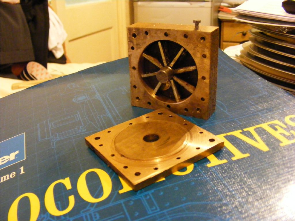 Hi I made this small turbine some years ago. With 25psi it will produce 10000 rpm. I had a hell of a job trying to balance it enough so I did not have to screw it to the bench. The turbine it's self is 1.3/4” in diameter and has 8 blades. It was made as an experiment to drive a locomotive throw a gear box which it did quite well but the gear box was far to big as I needed to get 10000 rpm down to 60 rpm.
I have just tried it driving a small DC motor that I got from the local model shop for £6.50. it has an out put of 12v @ 3 amps @ 1000 rpm. I connected then together with a bit of plastic tube and put my meter across the out put of the motor and apart from the noise it went well and lit a car head lamp bulb until the plastic tube broke. I will pick the bits of the tub out of the roof later.
James. |
| Paul Horth | 14/01/2011 10:37:52 |
| 69 forum posts 18 photos | James,
Thanks for the photo. Your model certainly shows that it's not necessary to use blades with difficult shapes to get a working result. If your turbine produced several watts then that is an impressive performance.
Could you tell us please how the steam enters and leaves your rotor? I can't tell from the photo.
And, could you please give some details on the motor? The power of 36 Watt would seem to imply quite a large motor.
Thank you
Paul |
| wotsit | 14/01/2011 18:18:16 |
| 188 forum posts 1 photos | Hi, Paul, I can scan the Chaddock Turbine articles in the next few days - the easiest way would be to e-mail them to you as PDF files - I am not sure if I can add them as attachments via the 'Message Member' facility of this thread - if not, you could send me an e-mail address via the MM facility, and I can reply privately. Keith |
| William Roberts | 14/01/2011 20:22:32 |
| 27 forum posts | Hi Paul,
We have a member known as Windy ,aka Paul who was making a turbine last year to drive a model speed boat , the last pictures I saw were the test nozzels he had made .I think he could help you . I cannot see why you need anything running at 90,000 rpm ? if you need more power increase the number of stages , I take it you know about the higher the pressure the greater the temperature = more work. I will drop Windy a line and see if he will help you im sure he will.
Regards Bill. |
| Werner Jeggli | 14/01/2011 22:16:23 |
| 28 forum posts 6 photos | Paul, Edited By Katy Purvis on 01/06/2015 11:25:39 |
| Paul Horth | 14/01/2011 23:15:28 |
| 69 forum posts 18 photos | Werner,
Thank you for your message. I have the magazines somewhere in the spare room, I will retrieve them and read about your turbine once again. I hope that your amazing train is running well, I consider this to be a heroic achievement of true model engineering. You have designed and built several complicated interacting systems and made everything work. I know how difficult that can be.
I would be interested in the details of the Swiss motor that you used as a generator, I expect that you have described that in the magazine.
Best regards
Paul |
| Stephen Rowley | 15/01/2011 08:13:16 |
| 57 forum posts 14 photos | Hi Paul
Sorry I forgot about the in and out. The steam or in this case the compress air enters by a 1/8 hole at the top left hand side and out at the bottom right. There were two more units one with 6 blades and the last with
4 and they were all on the one shaft. The air (steam) would enter the
first then into the second and the n the last. The motor is just a standard motor that is for R/C cars so has a lot of out put for it's size. As you an see from the photograph the winding are quit large for the size of the motor. James.  |
| Paul Horth | 15/01/2011 11:16:47 |
| 69 forum posts 18 photos | James,
Thanks. I have looked up this motor and found this data, and a lower price!:
Mtroniks Vision 500 Marine Mtroniks Vision 500 is a 540 size Johnson motor This 540 sized Johnson high speed motor is ideal for marine use. Unit comes complete with motor suppresion capacitors. Dimensions : L57.0mm D36.0mm Shaft diameter 3.0mm Voltage, 12V Off load current, 1.18A Max current, 54A RPM, 16500RPM Part No: V500M Price: £4.99 (Including VAT at 20%) This could be what I am looking for. From the data above I can calculate the performance as a generator and see if it could match the turbine. The speed is one of the highest I have found. I would then have to design a robust coupling and frame to hold the turbine and motor together. Thanks for the help Paul |
| Ian S C | 15/01/2011 12:54:18 |
 7468 forum posts 230 photos | Last week I did an experiment with a hot air engine I am developing, it sits on a stove, and has a fan in place of a flywheel. I attached three magnets to the hub of the fan and placed two coilseithe side of the motor , and as close to the magnets as I could, this rough set up generated enough power to light up two LEDs, one red and one green, but not quite the current to run a 3V radio. The motor was running at about 400rpm. This would indicate that the suggestion of embedding magnets in the turbine wheel with a coil near by should work. Ian S C |
| Paul Horth | 16/01/2011 19:27:44 |
| 69 forum posts 18 photos | Better late than never?
I have now re-read some of the turbine articles discussed above. The year 2008 Model Engineer had no fewer than three articles on miiniature steam turbines. Plenty for me to digest.
In several model turbine designs that I have seen, the blade or impeller cavity is a semicircular cutout formed by an endmill in the periphery. This is relatively easy to form and gives a kind of impulse action but is nothing like the impulse blades on a full size turbine. I have called these impellers "Stumpf" but I am not sure if this is the correct name. For these wheels, the steam jet is tangential. In some designs the steam jet is on the wheel cente line, so that the steam impulse is directed straight at the cavity, and the steam dissipates in all directions after hitting the wheel.This is not very efficient. In others, the jet is offset to one side so that the steam flows around the semicircle and is reversed. This is a better way to capture the steam energy.
For a more efficient impulse blade, the steam is fed in from the side of the wheel, flows through the blade and out the other side, reversing its direction but keeping a high velocity. It is more difficult to cut blades suitable for this action.
I will briefly summarise the turbines in the 2008 articles, as they represent these different types.
(1) Raymond McMahon, No. 4332 and 4334 15-8-08 and 12-9-08.
This turbine has the semicircular cutouts with the jet on the centre line. Diameter is 1.5 inch, 31 mm. It drives a dynamo from a rechargeable torch. The power and rpm are not stated, but probably in the tens of milliwatts, to light some LEDs. The housing has been made to look very realistic.
(2) Malcolm Stride, No. 4328, 20-6-08
These are for driving a boat not a generator. Two wheels are described.
Wheel 1: Blade shape is hard to see in the photo. Dia 50 mm.Speed 105000 rpm, down to 30000 rpm on load. Performance - drives a 3.5 foot boat.
Wheel 2: Blade shape semicircular cutout, with jett offset to the side. Dia 40 mm. Speed 90000 rpm to 40000 rpm on load. Performance - drives a 4.5 ft boat.
This indicates to me that the blade shape of the second wheel gave an improved performance. Note the high speeds though.
(3) Werner Jeggli, no.4318 and 4320.
Herr Jeggli's wheel is closer to a true impulse wheel, with side inlet and outlet and narrow curved passages in the periphery. Diameter 30 mm.Speed 53800 rpm no load, 34000 rpm at load. Power 4.4 watts. Smaller than the other wheels but I suspect more powerful because of the blade design.
When or if I make an attempt, I would aspire to make this kind of wheel, though i agree that the othr wheel do work and are thus good enough. It will also depend on what kind of motor I can use as a generator.
Paul
|
| Versaboss | 16/01/2011 23:23:22 |
| 512 forum posts 77 photos | Hi Paul, if you need a motor which will not disintegrate at turbine speeds, look at the so-called inrunners as used by the aeromodellers. See e.g. this site: http://www.jethobby.com.sg/cgi-bin/ezsite/index.cgi select 'brushless motor', then 'GS inrunner' The first I see, B-12-30 (12 mm dia, 30 mm length will turn over 45000 rpm on 12 v, and pulls 3 amps. And there are others, even faster. Even if it possibly is somewhat less as generator...impressive. I admit that I have absolutely no experience with these or wit any similar motors. But that's what I would look for.
Greetings, Hansrudolf
Edited By Versaboss on 16/01/2011 23:23:50 |
| DMB | 17/01/2011 10:34:40 |
| 1585 forum posts 1 photos | I seem to recall a steam gen. described in ME possibly back in 1970`s and the name of now late(?) Basil Palmer, South Africa.
John. |
| Paul Horth | 17/01/2011 16:48:43 |
| 69 forum posts 18 photos | Hansrudolf,
Thank you. That certainly is a fast speed. Do you know if this type of motor can be run as a generator?
This site seems to be in the USA, but I will look around for a UK supplier.
Paul |
| Versaboss | 17/01/2011 23:46:39 |
| 512 forum posts 77 photos | Paul, no they are in Singapore, and the prices are Singapore dollars (100 SGD = 49 GBP according to my converter). But it seems they don't have an online shop; I was a bit mislead here myself. Edit: or maybe they have? I see now a 'add to cart' on some items! Surely you can find a shop catering for aeromodellers, or try Ebay. As I said I have no experience with these motors, but as they are principally ordinary DC motors (but with the windings outside and a magnet rotor in the case of an inrunner) I see no reason why they would not work as generators. Edit 2: maybe the 3 leads would need to be connected to the usual 2 (+ / -) with diode bridges, if my theory of their working is correct. I remember that quite a time back someone wrote an article in MEW about building an outrunner (where the windings are inside and the case with the magnets turn) for driving a milling spindle. These are not so fast, but have more torque. I'm sure someone will bring forth the number of that issue. Greetings, Hansrudolf Edited By Versaboss on 17/01/2011 23:49:44 Edited By Versaboss on 17/01/2011 23:58:52 |
| AES | 18/01/2011 16:14:15 |
 85 forum posts 1 photos | For Paul Horth,
If you're looking for UK suppliers of aeromodeller's electric motors (of all types) then do no more than visit WH Smith (or similar) and buy the latest copy of magazines like "RCM&E - Radio Control Models & Electronics"; or "AVI - Aviation Modeller International". In both you will see pages and pages of ads for suppliers for such, ranging from big swish model shops to small 1 man band cottage industry-type outlets.
Motors for all types of aero models (and cars too I think) have come on in leaps and bounds in recent years, and the power outputs, ampere ratings, sizes, and types (brushed, brushless, outrider, inrider, etc) are many and various.
I'm sure you can find something suitable for your needs - and if faced with the confusion of too many choices, both of the above mags have regular columnists who specialise in electrics who could no doubt answer queries.
Good luck.
Krgds
AES |
| Ian S C | 19/01/2011 09:14:41 |
7468 forum posts 230 photos | The model aircraft suppliers have alternaters for engine driven power supplies.
The generator I'm using on one of my newer engines is the motor out of a Braun stick blender, this is a bit the opposite of what you want, at around 1000rpm i'm getting 18V, if the generator is run up to full speed it would produce 220V, it's a 500W motor about 60mm long X 30mm dia. Ian S C |
| Les Jones 1 | 19/01/2011 15:36:20 |
| 2292 forum posts 159 photos | Seeing Ian's suggestion of using a motor from a blender made me remember some information I had seen on one of the Dyson battery vacuum cleaners. The DC31 is claimed to use the fastest motor in the world which runs at 104000 RPM. As this motor will have a rotor on the end of it it is almost a ready made turbine generator. I imagine it uses the same basic design as model aircraft motors so it would need the inverter electronics removing and being replaced with a three phase rectifier. Here is a link to a web page with a little information about it. Les. |
Please login to post a reply.
Magazine Locator
Want the latest issue of Model Engineer or Model Engineers' Workshop? Use our magazine locator links to find your nearest stockist!
Sign up to our Newsletter
Sign up to our newsletter and get a free digital issue.
You can unsubscribe at anytime. View our privacy policy at www.mortons.co.uk/privacy
Latest Forum Posts
- hemingway ball turner
04/07/2025 14:40:26 - *Oct 2023: FORUM MIGRATION TIMELINE*
05/10/2023 07:57:11 - Making ER11 collet chuck
05/10/2023 07:56:24 - What did you do today? 2023
05/10/2023 07:25:01 - Orrery
05/10/2023 06:00:41 - Wera hand-tools
05/10/2023 05:47:07 - New member
05/10/2023 04:40:11 - Problems with external pot on at1 vfd
05/10/2023 00:06:32 - Drain plug
04/10/2023 23:36:17 - digi phase converter for 10 machines.....
04/10/2023 23:13:48 - More Latest Posts...
- View All Topics
Support Our Partners


Shopping Partners
Subscription Offer

Latest "For Sale" Ads
- Reeves** - Rebuilt Royal Scot by Martin Evans
by John Broughton
£300.00 - BRITANNIA 5" GAUGE James Perrier
by Jon Seabright 1
£2,500.00 - Drill Grinder - for restoration
by Nigel Graham 2
£0.00 - WARCO WM18 MILLING MACHINE
by Alex Chudley
£1,200.00 - MYFORD SUPER 7 LATHE
by Alex Chudley
£2,000.00 - More "For Sale" Ads...
Latest "Wanted" Ads
- D1-3 backplate
by Michael Horley
Price Not Specified - fixed steady for a Colchester bantam mark1 800
by George Jervis
Price Not Specified - lbsc pansy
by JACK SIDEBOTHAM
Price Not Specified - Pratt Burnerd multifit chuck key.
by Tim Riome
Price Not Specified - BANDSAW BLADE WELDER
by HUGH
Price Not Specified - More "Wanted" Ads...
Get In Touch!
Do you want to contact the Model Engineer and Model Engineers' Workshop team?
You can contact us by phone, mail or email about the magazines including becoming a contributor, submitting reader's letters or making queries about articles. You can also get in touch about this website, advertising or other general issues.
Click THIS LINK for full contact details.
For subscription issues please see THIS LINK.
Digital Back Issues


Donate

 Register
 Log-in
Model Engineer Magazine
- Percival Marshall
- M.E. History
- LittleLEC
- M.E. Clock

ME Workshop
- An Adcock
- & Shipley
- Horizontal
- Mill

Subscribe Now
- Great savings
- Delivered to your door

Pre-order your copy!
- Delivered to your doorstep!
- Free UK delivery!
All Forum Topics > Miscellaneous models > steam turbine and generator