Forum sponsored by:

New I/C diesel project - ETA15d-x2
| Ramon Wilson | 08/05/2011 22:59:30 |
 1655 forum posts 617 photos | Just an update on finishing these liners off.
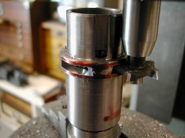
The original ports were required to be cut in with a woodruffe cutter with the edges ground at a fifteen degree angle. A cutter blank was turned to this spec from silver steel and the teeth milled in then bearing in mind the problems experienced on the Racers with insufficient backing off due course was paid to this by filing before heat treating. Quenched in oil it was left untempered and the cutting edges touched up with a diamond lap. It sailed through all sixteen slots with ease, no coolant, chipping well in the EN1a and no rubbing.
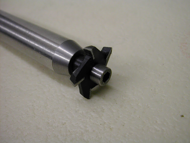   The exhaust width at the inner face looked very small but comparing it to the original liner it appears in reasonable proportion. It's fair to say I'm well pleased.
Not much more machining to do now - just the pistons and conrods plus the incidentals - needle valves and comp screws and the lapping in of pistons and liners of course.
Hope this is still interesting for some.
Regards - Ramon Edited By Ramon Wilson on 08/05/2011 23:01:32 |
| Bill Pudney | 09/05/2011 01:02:37 |
| 622 forum posts 24 photos | This is all really interesting Ramon, keep up the good work!! About the woodruffe cutter for the exhaust ports.....is the cutter just secured to the arbor with a socket head screw? cheers Bill Pudney |
| ady | 09/05/2011 08:50:50 |
| 612 forum posts 50 photos | The ultimate aim for me is to make IC engines, got a long way to go yet but they are always inspirational to watch as they develop. It's worth getting a picture of whats involved in these things if a production run is required. The amount of jigs, lovely equipment and specialised tooling required is eye popping if you want to "automate" this kind of thing for even a small single cylinder unit. So to do it manually and achieve a good result takes an amazing amount of skill and effort. I recently ran across a sturmey-archer heritage website which has a 220MB film of the production processes involved to make those little enclosed 3 and 5 gear planetary gear hubs many of us cycled about with in our youth. http://www.sturmey-archerheritage.com/Production has now moved to Taiwan. Some of the machines in the shop, to ensure quality control and efficiency for production of the gear hubs, are literally as big as a bungalow. I never really realised just how much effort is needed to make even small decent quality engineering until I took up this hobby. |
| Ramon Wilson | 09/05/2011 20:45:42 |
1655 forum posts 617 photos | Hi Bill,
That's good to hear and I hope you're not alone as I always wonder if I'm posting too much. I would not like to be seen to be seen, or even considered as so, as doing it for egotistical purposes. Other than this forum I have very little social contact with others of similar interest so I see sharing what I have done as much like taking it along to a club meeting. The big thing on here as opposed to that is that it's far more regular and reaches people with a direct interest in the subject - not many with I/C interest in the average club I guess. You may have seen some of it on the Barton C/L Forum - that's where I went to get some information on the originals at the early stages of the build.
Ady, I don't know where you are with regard to starting the hobby but building a small I/C engine is really not that difficult. You do need to accept that fits have to be good, particularly on the liner and piston and pay due care to ensure success but you don't need oodles of kit to achieve it. It does, however take time to asemble bits and pieces to make things easier. By starting with something relatively easy, preferably with a basic crankcase machined out of solid - there are some designs where this is just a basic block - and taking each stage slowly and with thought to the next part to fit I think you may surprise yourself with the end result.
Personally I would begin with a diesel or a glow because petrol adds another dimension with the ignition but that's down to choice. I still have the pleasure of a first sparky to look forward too but whilst that was on the cards until recently there are now one or two other diesels that have somehow pushed their way into the queue
 Thanks to both of you for your kind comments
Regards - Ramon
PS
The cutter Bill is a separate item to the mandrel. It is held by a 4mm cap head which had the head turned down for clearance on the exhaust flange. To ensure concentricity the 6mm diameter stem on the cutter itself locates 6mm deep in a hole bored in the mandrel
Edited By Ramon Wilson on 09/05/2011 20:54:19 |
| James B | 09/05/2011 21:01:32 |
 101 forum posts 14 photos | Hi Ramon, I always read your posts with interest, although I'm afraid i'm not always very good at actually posting a reply... Its nice to see other peoples approaches / setups - even if not relevant to a particular project at that time, you can often apply an aspect of it or may be useful at a later stage. Like you I don't belong to any clubs, both for reasons that my time is limited and also my interests lean toward IC engines and road steam, rather than locomotives, so seeing other peoples projects progress is nice. Keep them coming! James |
| jomac | 12/05/2011 11:19:11 |
| 113 forum posts | Hi, first ADY dont make the Bolaero 18 off the MEN site, unless, like me do a scaled up drawing of the plans, because, I found that the bottom of the piston did not allow enough of an opening when the piston was at TDC, I had to file out sections of the skirt to get the timing right, then It could be just me not reading the plans properly. Ramon, The engine is a David Anderson Satilite 1cc. After much thought and dilema I did not do as you suggested,and that was to bore out the cylinder first, then do the transfer ports after, cause as the transfer ports are on the inside wall of the cylinder, and the 2.5mm carbide end mill is too short to mill down to 10.28mm, So I brought 2 carbide drills, then drilled down to 10.5mm, followed with the other drill which I had sharpened on the T&C grinder as an end mill. there are two port opposite each other, 2.5mm diameter spaced 1.7mm apart, Then drilled out the cylinder 10.5mm, tried to bore out the hole, but as the only boring tool that would fit was a carbide tipped 3/8" tool, It seemed to hit hard spots, and was waisting the bore, THINKS???,. found some concrete reinforcing bar, (reo bar) 1/2" diameter, now reo is tough, and comes in various sizes (the ones with formed spirals and straights) its also cheap ie, free of building sites. DONT!!!! put it straight in the lathe and try to cut off the lumps with an indexable or carbide tipped tool, they shatter, which is not good for unprotected eyes, just use a heavy duty bench grinder or large hand grinder, to get it reasonably smooth, I did that and reduced it to 10mm, plus a further reduction to 9mm for about 50mm long, drill and tapped the end 5mm cap head screw and cross drilled to take a piece of 1/8" round, formed a knife edge tool shape, with the T&C grinder, Did it work YES!!! I started to bore it out, but only just taking out the waisted section, to start with, followed by finer cuts to get it all smooth, Just to see if it would work, I milled off a section off the other end, down to just above center hight, marked that out to take a very small diamond/trapesium shaped indexable bit, and screwed it down with a 3mm round head bolt.( the hole is 2.95 diameter) so be careful when drilling, The negative angle on my other indexable boring bars varies 5-10 degrees, But the tool bit bit is parrellel to the long axis next time I will leave the end 12mm so that there is a bigger landing for the bit, then take off the rear to give clearance. They both work, with no chatter or undercutting, reo bar, when cut square also make very strong tool holders, (I have a crowbar 5/8" round which I cannot bend) and being an old age pensioner they are cheap as. Sorry to be so long winded, but hope it helps someone out there. John Holloway.
|
| Ramon Wilson | 13/05/2011 20:41:58 |
1655 forum posts 617 photos | Hi John, I guessed as much (DA Sattelite) from the holes and spacing you described previously - I received my MEN disc last week and first thing I did was check out the extra designs and spotted it in there.
Following on from your PM and this post it serves to show that there are always several ways to skin the proverbial feline. It's how you arrive that matters not so much the means of getting there. I must admit though that using reinforcing bar as you have is certainly thinking 'outside the envelope' but again, if it works ......... "Where theres a will" definitely springs to mind here John.
I've had a very busy garden day today but yesterday I found time to visit my friend Lee and use his blasting cabinet. All the relevant parts are now bead blasted and the result was well worth going
 Once the pistons are done next week the final parts should not take too long then there's the anodising and trying this nickel plating on those needle valve parts. Once the pistons are done next week the final parts should not take too long then there's the anodising and trying this nickel plating on those needle valve parts. Thanks for your comment James, it is difficult to know at times if it serves a purpose but from the odd comment and occasional PMs received I guess it is met with favour most of the time - I'll 'hang on in there' then
Regards for now - Ramon |
| John C | 13/05/2011 22:39:08 |
| 273 forum posts 95 photos | Hi Ramon,
Long time watcher and lurker here - your posts really are very much appreciated no matter what the subject. Please do keep up the good work - I always learn something from reading your submissions.
Best regards,
John
|
| jomac | 14/05/2011 11:43:33 |
| 113 forum posts | Ramon. Hi. First I dips me lid to you, cause my finishes are no where as good as yours. Maybe its because I get impatient and tend to cut off great chunks of swarf, and that does not leave enough metal to machine and file down for a fine finish. Now, reo bar, Iv'e got two examples on how tough this stuff is, the first is a crow bar I used take with me when fossicking for Saphires, it does not flex as much as my other two good crowbars. The second, is when I made a draw bar for my indexer out of 6mm plain round rod, (which had been left outside for 20 years) and had very little pitting in it, I tried to cut a thread with a non adjustable die, it would not touch it !!!!! so I had to go and buy an adjustable die, and run that up and down a number of times just get a good thread. I have no idea what type of steel is in reo bar (concrete reinforcing rod), maybe some one out there knows ???? I think there is some for of rust inhibitor, combined with other stuff, cause it does not rust much, When I went to up grade my welding tickets, 30 years ago, we had to go to Woolongong, which is 350ks east of Canberra, one of the places we went to was a steel mill, they were running red hot rod through a former, to get the raised spiral on it, it then went past a cooling spray, So is it now forged and heat treated ???? Anyway I now know it makes good boring and other tool holders. Ramon, I agree with other writers of posts, Why dont you submit your articles to Model engineer, you would make very very good replacement for Nemett ( Malcom Stride). Thanks John Holloway PS the weather down here in the Southern Tablelands is brilliant -5 degrees upto 19 degrees, but dont worry it will get colder.!!! |
| Ramon Wilson | 21/05/2011 23:34:00 |
1655 forum posts 617 photos | Hi all,
The last few days has seen some steady progress so a few more pics but first thanks for the kind words of support John C and also for yours John H. I hasten to stress I do not see myself quite as you do with regard to the magazine after all this (making I/C engines) is still a fairly new area to me however I have been steadily working on an article which is nearing completion so hopefully that news will whet your appetite
.Regarding finish John, whilst I do not 'strive' to achieve such I do ensure that the last cuts are fine ones and the tools nice and sharp in order to keep tool marks to a minimum. As I have mentioned before I swear by the use of the Garryflex abrasive filled rubber blocks. For those who may be uncertain these are not the abrasive coated sponge rubber blocks seen in DIY stores but solid blocks of rubber with the abrasive running throughout. Four grades from coarse to fine and, when used with a lubricant - I normally use parafin - will produce a silky smooth finish to most metals but particularly so on ally and mild steel. One nice thing about them is that you can shape them with a scalpel or slice quite thin portions off them in order to be able to get into narrow grooves etc.
I don't know if you have anything similar in Aus but they are readily available over here.
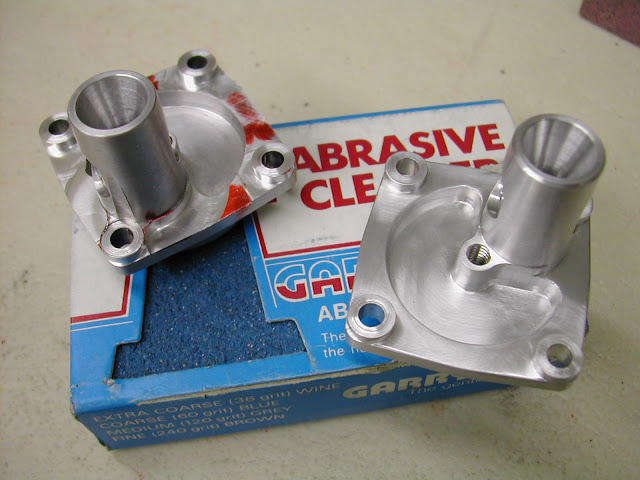 This shows the backplates after some further milling around the bolt holes to be more in keeping with the original and fettled with the blocks sufficient ready for bead blasting.
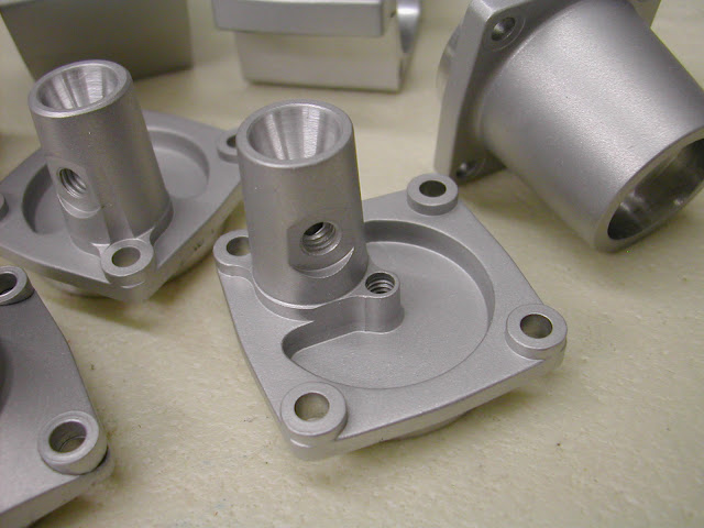 This is how they looked after. As said before I do have acess to a good friends blasting cabinet but this is proving such a good way to finish I'm intent on setting something up myself in coming months. Other work accomplished is the lapping of the liners and pistons and then the pistons to their respective liners. One home made lap did all three liners to a plug gauge and with lesson learned by trying to rush the pistons on the Racers I made a piston lap before starting
 I have made this type previously - the time to make one is definitely worth the effort.
Something that may be of use to someone....
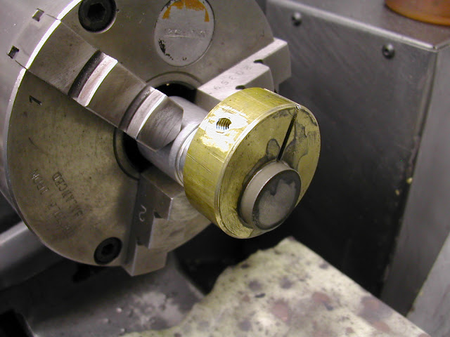
The pistons were cross drilled in situ on the lathe using the cross slide drilling attachment. I don't know how but all three holes were .04 mm out of square to the bore. I must have had the attachment slightly out of square but it was all taken down before I noticed the discrepancy so I'm not sure. Fortunately though, although I had originally intended a 5mm pin I had used 3/16 as I had a good supply of dowels which are ideal for wrist pins. The pistons were set up in the vise and the hole aligned using a 3/16 rod in the drill chuck. A 5mm FC3 cutter then had two flutes ground away then finally a light touch on the wheel to reduce the remaining flute to leave enough for reaming. Used in the drill chuck it worked a treat and the holes all re-aligned
 Whilst there is still quite a bit to be done the end is now in sight. Currently the con-rods are being machined and there are still one or two bits outstanding on the third version but hopefully it won't be long before theres a certain whiff of 'diesel' in the air.
Once again thanks for your interest
Regards for now - Ramon
|
| jomac | 22/05/2011 11:35:19 |
| 113 forum posts | Ramon Hi. Ron Chernic has a good method for drilling the pistons, first before taking them out of the chuck he scribes a center line on the bottom of the piston, then on a face plate he has scribed a vertical line, he then aligns the piston marks with these on the face plate, lock the piston to the face plate, I did the same, but to align the piston properly, had drilled a small hole on the top edge of the face plate, then put the same drill in the mill chuck, and dropped it down into the previously drilled hole, In theory everthing now lines up. A small amount of Super glue allowed me to even things up before the glue dried, then clamped the piston to the face plate. Quicker to do it than write about it !!!!!!. The other thing is, Contra pistons. in the MEN articles Dave Owen " 2.5cc Mate" Dave machines the contra piston nearly down to the right diameter, then puts a taper on the INSIDE of the CP parts it off, glues the hollowed out section to stub mandrel, faces of the end, then using a thread die holder, which has a slotted and grooved aluminium lap in it (the tightening screw adjusts the lap in or out), and then laps the CP so that lower half just slips into the top of the bore, the top half is a tight fit, Now because the inside of the CP is tapered, it now gives a very good seal, Using this method you only have to do one ???, not half a dozen miss fits. I did try to find that article in MEN, BUT its not in the Owen files, I think from memory, its refered to in another article, for some other IC engine. PS there is some good aricles in the COOKIES. and have you finished concreting, I have not, I did me back in when I fell of the small ladder, when I was cutting down trees. Thats my excuse,!!! im'e sticking to it, It gets me out of more work John Holloway |
| Ramon Wilson | 22/05/2011 23:42:09 |
1655 forum posts 617 photos | Hi John,
I'm not quite sure I follow this method of Ron's but will check it out - since getting the MEN disc I've had little time to really delve into it.
Somewhere previously though, I have read about the internal 'tapered' contra piston method and it's easier fitting. Infact I did have a go at one for the Racers but totally missed the principle of reducing the lower portion to fit leaving the top a push fit as you describe. I couldn't see the benefit with it all a push fit and having a tapered bore behind to grip on so I went back to the conventional(?) way. I'll have another go on what ever's next as I can certainly see it should be a lot easier than getting that exact 'micro' fit required for a parallel version
That said I have just done the Eta's CP's lapping them parallel with the piston lap and held them by turning an expanding mandrel down to a push fit in the reverse bore, removing the screw from the mandrel and letting the spring in the mandrel 'fingers' grip the CP. That worked well. The third engine has a composite CP - a fixed outer held captive by the cylinder head and a small inner 10mm dia moveable part which has a hemispherical chamber. This was bored 8mm on the reverse and held on a very slightly tapered mandrel for lapping. Now you've said however I can see this would have been a lot easier with a spot of Cyano but would never have thought of using it as a temporary means of holding. I'll certainly give it a try in the future. I'm assuming slight heat will soon break the bond though a sharp tap should do too as CA is not that strong in shear.
Yes the groundworks are complete, not that there was much of it - just getting old and sedentiary. Far too much time in the workshop and not enough exercise (Exercise ?
 ) )according to you know who.
Regards - Ramon
Edited By Ramon Wilson on 22/05/2011 23:44:41 |
| LADmachining | 22/05/2011 23:51:50 |
 126 forum posts 11 photos | The how-to on how to make the contra-pistons is on Ron's website under 'Resources', 'FAQ', then item number 8.
If you want to navigate there directly, it is on page 6 of the Weaver construction log.
These pages mention an *external* 1 degree inluded angle taper on the contra. The OD is the only place the taper can be cut into when the contra is temporarily fixed to a mandrel by it's ID.
 I have used this method exclusively to make contra's for my Diesel engines, and it hasn't let me down (other than mistakes on my part).
Keep up the excellent work Ramon.
 On a side note - I nearly made it out to the workshop myself the other day. Will spend some more time out there soon, with a bit of luck - plenty of work to be getting on with out there, that's for sure. On a side note - I nearly made it out to the workshop myself the other day. Will spend some more time out there soon, with a bit of luck - plenty of work to be getting on with out there, that's for sure. |
| Ramon Wilson | 23/05/2011 21:01:02 |
1655 forum posts 617 photos | Hi Anthony, You'll get there, don't despair too much
.Thanks for the reminder. Having reread it, it is the info that inspired me to have ago on the Racers. I must have disposed of the scrapper, well couldn't find it today, but I recall that I did taper the outside to a 1 degree included angle and also the inside for some reason. I have a feeling I felt the thin wall was giving insufficient pressure for the 19mm bore so went back to the more conventional method. Even then I had to 'grow' one of them by heat treat as I over lapped it.
I must admit reading what John has said it seems that having the initial part a good slip fit in the bore then bringing out the remainder at an angle seems worth pusuing but I'm still not sure about a wall thickness of 25 to 50 thou
What's the largest bore you have made them for?
Con-rods are underway at last but no machining today - swmbo cracking the whip in the garden
 Regards - Ramon |
| jomac | 24/05/2011 12:37:13 |
| 113 forum posts | Ramon, just to clarify a few thoughts in my head, First when drilling the pistons, I said that I use a drilled hole in the face plate? That should have read angle bracket, also instead of using a drill to align the bracket, the hole I drilled is big enough to fit a piece of drill rod or similar, that saves on breaking drills. To also get a fairly good center for the drill, I also put a 6" ruler below the drill, or a tapered piece of hard round bar and, carefuly traverse the mill table back and forth. When the rulers is parrallel to the table, you now have center, use a center drill to start the hole. Secondly the contra pistons I make, have an internal 5-10 taper, some times more, that gives enough meat around the base of the CP, I also try the CP in the bottom of the cylinder, as that should have a taper when they were lapped, the external taper is minimal, just enough to make a good gas tight fit. ie its very hard to push it down, If it looks right, it must be right.!!!!! If they are made properly when you screw the CP down, then release the pressure, one swing of the propeller you should hear the CP make a noise when it hits the adjusting screw. An idea I saw for making conrods was to go down to your local bicycle repair shop and get some worn out/broken pedals, the good ones are forged aluminium alloy, I have no idea what they are made of ????, but they are tough, being forged, apparently the metal molecules are aligned length wise, which is good for conrods, and make a good bearing surfaces, the best thing is, they are generally free, you find lots of goodies in the scrap bin. Its getting late at night, Im'e tired, so am I making sense. John Holloway.
|
| Ramon Wilson | 24/05/2011 23:21:16 |
1655 forum posts 617 photos | Hi John, Me too, I've just got carried away about painting and am off for an early(?) night with the new copy of MEB
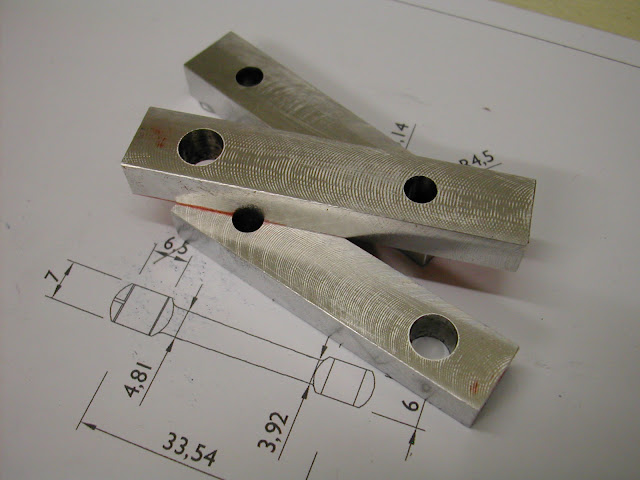
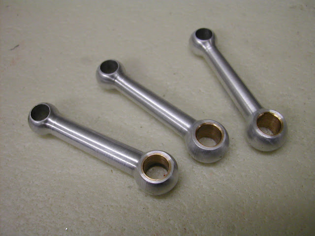
Thought you might like to see these though, made them today, first time I've turned conrods so well pleased
Bit more later |
| Ramon Wilson | 25/05/2011 11:02:19 |
1655 forum posts 617 photos | What is that phrase about " Eats shoots and leaves"
That should have read 'first time I've turned conrods, so (I'm) well pleased'!
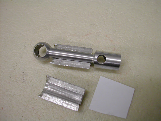
To date all the conrods made have been milled. I have fought shy of turning them so far because of the perceived problem of holding them to finish off radiusing the ends - so much so that they were drawn out as rectangular section to be milled instead
However the original Eta engines had turned rods so it was a case of biting the bullet and at least having a go. It proved far more easier than anticipated.
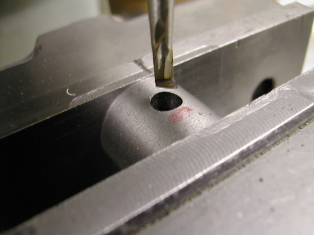
First blanks were milled and the holes drilled and reamed in the mill to ensure parallelism. Two were milled square section for subsequent turning and, in case this proved a disaster, three were milled to a rectangular section for milling.
 Having decided to try turning a form tool was made from gauge plate and hardened but not tempered. The blanks were set up and the ends centred and turned to round section and the tapered shank turned to finished diameters. The form tool was made to be able to cut to finish diameter but leaving a 2mm centre portion that would hopefully be sufficient to hold it for the small end. The plan was to remove this after and finish by hand filing.
 'Neccessity being the mother' etc created a split tapered collet to grip the shank and this proved the solution. With a slip of paper in to improve the grip this worked very well and both ends (the big ends were recut to reduce the size slightly) were formed holding by this method.
 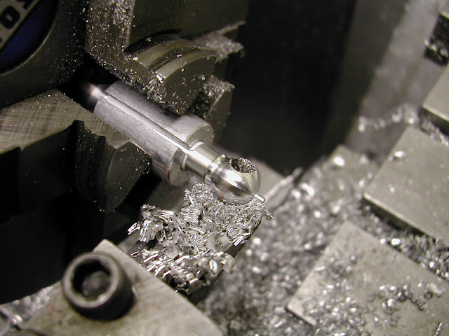 The ridge was turned with a round nose tool flaring the ball end into the shank.
This turned out to be a totally succcessful operation and, using one of the thinner rectanglular blanks a third was made with slightly thicker shank for the S&J version which is in fact correct to prototype. This method was definitely quicker and probably much easier to machine than milling on the rotary table so will definitely be used in the future. A smaller rod may prove more difficult in the collet needs boring and the hole may prove too small but a tapered D bit made at the same setting would easily solve that problem.
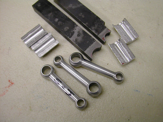 The form tools were just milled - the top rake milled first and the radii plunge cut in steps.
As aways hope this is of use to someone, now Its time for a clean up and then those Tufnol rotors
Regards - Ramon
|
| Ramon Wilson | 25/05/2011 11:52:58 |
1655 forum posts 617 photos | John, my apologies.
Yes I see how are doing the piston holes - I like the idea of finding the centre using a six inch ruler, thats how I set a lathe tool to centre height but never given a thought of doing the same on the mill. Something else learnt, small maybe but useful
Thanks for the tip on the bike parts too - I guess you are you refering to the crank arms as opposed to the pedals themselves. I do have some very 'tough' high tensile(?) aluminium which I use. I don't know of it's actual grade but where it came from it is used for making moulds for blow moulding plastics. It's lovely to machine and much tougher than HE30. If you try to hacksaw it it work hardens very quickly.
I've also bought some HE15 but as yet haven't tried it but with two Bike shops in town I shall certainly look in to redundant pedals a bit further.
Do you take Model Engine Builder? Lovely little radial in the latest issue - the drawings are truly a labour of love. Another project ? no not at this stage one or two more diesels lined up first
Regards - Ramon |
| Ian S C | 25/05/2011 13:45:19 |
 7468 forum posts 230 photos | I find that I can get off cuts of7075 T651 tooling Plate, this is a high tensile alloy, with a similar strength to steel. I have also used bike pedals, some are better than others.
Ian S C |
| jomac | 07/06/2011 11:58:19 |
| 113 forum posts | Hi Ramon and others. Iv'e been off the air for more than a week cause my ISP did an upgrade, and stuffed up the connection. So Ron Chernic, MEN, and Dave Fenner both had what looks like the DELIPINA external grinder and hones, Dave in his article on building the Sugden Special, mentioned the Grindall ??? that was an article by Allen Booth that was was in MEW. I asked Dave Clarke Feb 2010 if he could reprint that article, unfortunatly he could not get in touch with Allen Booth, but he did put up the digital MEW on this site, problem!!! I gave him the wrong number, Iv'e got a big gap in MEW around that area, So trolling the net, I found a site by Tom Blough. he built 3 external grinder/hones, he had modified them by adding a knurled, indexable screw, which gives minute adjustments to the tool, it seems a better item than the Delipina and the Grindall. Still on honing, I made an internal hone using 10mm round SS , machined a 3mm deep flat on one end, then Araldited a 4mmX4mm piece off a fine stone that I broken, and was for rubbing off the burrs from the deep grooves of a deep bowl, wood turning tool, these stones used to come in 3 sizes and 4 grades, one of them is 3" long 1 1/2" wide 1/4" at the thick side and tapered down to 1/16" on the narrow side, VERY fragile, To get it round I mounted the SS in the chuck and then with the Dremel with a 30mm diamond disc in it. mounted on the cross slide, traversed back and forth, and turning the chuck by hand, later switched the lathe on and got the hone round BUT 1mm higher than the SS. It worked????, engine oil, makes a messy sludge, Kero does a better job. I know this might raise the copyrite bugbear again but is it possible to down load a copy of Allen Booths article. Its been very cold down here lately, so have not been in the workshop. Bugger!!!!. John Holloway
|
Please login to post a reply.
Magazine Locator
Want the latest issue of Model Engineer or Model Engineers' Workshop? Use our magazine locator links to find your nearest stockist!
Sign up to our Newsletter
Sign up to our newsletter and get a free digital issue.
You can unsubscribe at anytime. View our privacy policy at www.mortons.co.uk/privacy
Latest Forum Posts
- *Oct 2023: FORUM MIGRATION TIMELINE*
05/10/2023 07:57:11 - Making ER11 collet chuck
05/10/2023 07:56:24 - What did you do today? 2023
05/10/2023 07:25:01 - Orrery
05/10/2023 06:00:41 - Wera hand-tools
05/10/2023 05:47:07 - New member
05/10/2023 04:40:11 - Problems with external pot on at1 vfd
05/10/2023 00:06:32 - Drain plug
04/10/2023 23:36:17 - digi phase converter for 10 machines.....
04/10/2023 23:13:48 - Winter Storage Of Locomotives
04/10/2023 21:02:11 - More Latest Posts...
- View All Topics
Support Our Partners


Shopping Partners
Subscription Offer

Latest "For Sale" Ads
- Reeves** - Rebuilt Royal Scot by Martin Evans
by John Broughton
£300.00 - BRITANNIA 5" GAUGE James Perrier
by Jon Seabright 1
£2,500.00 - Drill Grinder - for restoration
by Nigel Graham 2
£0.00 - WARCO WM18 MILLING MACHINE
by Alex Chudley
£1,200.00 - MYFORD SUPER 7 LATHE
by Alex Chudley
£2,000.00 - More "For Sale" Ads...
Latest "Wanted" Ads
- D1-3 backplate
by Michael Horley
Price Not Specified - fixed steady for a Colchester bantam mark1 800
by George Jervis
Price Not Specified - lbsc pansy
by JACK SIDEBOTHAM
Price Not Specified - Pratt Burnerd multifit chuck key.
by Tim Riome
Price Not Specified - BANDSAW BLADE WELDER
by HUGH
Price Not Specified - More "Wanted" Ads...
Get In Touch!
Do you want to contact the Model Engineer and Model Engineers' Workshop team?
You can contact us by phone, mail or email about the magazines including becoming a contributor, submitting reader's letters or making queries about articles. You can also get in touch about this website, advertising or other general issues.
Click THIS LINK for full contact details.
For subscription issues please see THIS LINK.
Digital Back Issues


Donate

 Register
 Log-in
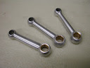
Model Engineer Magazine
- Percival Marshall
- M.E. History
- LittleLEC
- M.E. Clock

ME Workshop
- An Adcock
- & Shipley
- Horizontal
- Mill

Subscribe Now
- Great savings
- Delivered to your door

Pre-order your copy!
- Delivered to your doorstep!
- Free UK delivery!
All Forum Topics > I/C Engines > New I/C diesel project - ETA15d-x2