Forum sponsored by:

Groove/cutoff tools wants to dig in too much
| John Haine | 21/06/2023 20:32:56 |
| 5563 forum posts 322 photos | What rpm? |
| JasonB | 21/06/2023 20:51:29 |
 25215 forum posts 3105 photos 1 articles | And what metal? |
| Maurits van Dueren | 21/06/2023 20:58:25 |
| 22 forum posts 2 photos | Lowest poulie gear on the Myford for best torque, tried on the VFD from 30 to 70Hz, which translate from 210 to 500 RPM on the chuck. Low seemed most stable chatterwise, but it stalled too easily. Typically it stalls by the blade digging in, and the lathe then slipping the gearbelt, not to motor or the motorbelt. But I already have it very tight. I think when it digs in like it does, no belt or belt ratio will be enough torque, the trick is to avoid the digging in, not more power. I even tried running it by hand. (what is that? 6 RPM?) Manual scraping the iron basically. Same thing, goes well for a while, but then digs in. Which in that case cannot be chatter. --- For the rear toolpost, is it an option to buy a chunky bladeholder, and weld it to a suitable piece of steel?
|
| Maurits van Dueren | 21/06/2023 21:03:20 |
| 22 forum posts 2 photos | As to the metal, unknown but suspected a reasonably quality, but non-hardened one. However, as mentioned, I have this all the time. It is worse now, as this is the largest diameter i've tried and a bit away from the chuck, but I have the same problem with stuff that in Dutch we would discribe as pisspot steel
|
| speelwerk | 21/06/2023 21:21:16 |
| 464 forum posts 2 photos | Being a Myford from (I guess) somewhere the 1950's, is there perhaps too much play in the headstock bearings because of wear. Niko. |
| not done it yet | 21/06/2023 21:40:29 |
| 7517 forum posts 20 photos | Just a few more things to be aware of. Is the cutter positioned as close as possible over the centre line of the cross slide? That is the ideal position. How far from the chuck is this groove? The closer the better. Are you supporting the part from the tailstock? Every little helps, particularly if the groove is distant to the chuck. How far is the compound slide extended? The less the top slide is extended from its slide, the better (and tightened down - locked - securely). How much cutter overhang is there? The bare minimum is best. I adjust my parting tool extension for just over half way. If a large diameter, it gets adjusted more than once, starting short before extending. How good are the spindle bearings adjusted? if you have power feed on the cross slide, take extra care that the cut is stopped before the feed screw threads jam up! There may be more, but you get the idea that rigidity is paramount.
|
| Fulmen | 21/06/2023 21:51:25 |
 120 forum posts 11 photos | Have you tried changing the tool height? There is no law demanding it be on center. Small tools flex, sometimes it helps to raise the tool slightly. |
| Chris Crew | 21/06/2023 22:10:01 |
 418 forum posts 15 photos | My method of parting and grooving is with a good old fashioned J&S type holder with an Eclipse parting blade ground with about 5deg. front clearance and top rake (bottom rake as it's inverted) mounted up-side down in a rigid rear tool post very slightly above centre-height. Moderate speed, plenty of suds and a confident steady feed. Anyway, it works for me. All good quality lathes are made to face very slightly concave, so even if the tool is set at 90deg. to the work it will always be at a very slight angle to the work. This doesn't stop you from parting off or grooving successfully but just be aware of this design feature. |
| Kiwi Bloke | 21/06/2023 22:57:48 |
| 912 forum posts 3 photos | Maurits, take heart, you're not alone. Parting, or even 'normal' turning with a tool with a large nose radius causes folk a lot of problems on small lathes. Essentially, it boils down to the desired relationship of the tool's tip and the work piece being disrupted, either by unwanted movement, or unintended forces. Myfords are relatively flexible, especially if using the topslide, and, as has been said, free movement of workpiece may be caused by worn mandrel bearings, or free movement of the tool may be the result of slop in the feedscrew nut or the feedscrew's thrust bearing, which is awkward to adjust nicely. In another thread, I asked why some early lathe-use books (and not so early: it's included in South Bend's 'How to Run a Lathe' A properly set up cutting tool experiences three forces: 1. force of feeding, towards tailstock; 2. away from the workpiece, pushing the tool out of cut; 3. tangentally downwards. This last force is by far the largest. It will try to bend the tool's support, and this will result in the tool cutting deeper - an unstable condition that will end in tears. It is important for there to be a force pushing the tool away from the work, because this takes up the feedscrew's two backlashes. The direction of force 3 (and therefore its horizontal radial component) is the major determinant of whether this occurs or not. If there is any inwards component of this force, the tool will get 'sucked in'. The idea of setting the tool on centre height (apart from avoiding facing pips) is to ensure this force is vertically downwards. If the tool is below centre height, the tangential force swings round, so there is an inwards component, trying to pull the tool inwards, deeper into cut. Of course, flexibility in the machine allows the tool tip to be deflected downwards, so it's all rather difficult to achieve theoretically correct conditions, all the time (ever?). Avoiding this is the justification of rear tool posts, with inverted tools: they deflect upweards and swing out of cut - a stable condition. The idea of setting the tool tip above centre height (tangent point about 5 degrees rotated clockwise, as viewed from tailstock), is to direct the tangential force 3 so that there is an assured outwards component, hopefully keeping the tool pushed outwards. Also, of course, it allows for downwards deflection of the tool. Beware of tools being below centre height. This is an unstable condition. At first sight, it looks attractive: a 'scraping cut' has to be safer than a 'proper' cut, doesn't it? Well, no! Emphatically no! |
| Kiwi Bloke | 22/06/2023 03:38:53 |
| 912 forum posts 3 photos | Apologies for the yellow winking thingie in previous post. Too late to remove it now. Grrr! Just for clarification, before someone tells me that raising tools above centre height will prevent them cutting because they'll rub. What I've said assumes that tool angles are adjusted to account for the centre height variation. Think of it as rotating the tool and its point of contact clockwise about the lathe's axis, viewed from the tailstock. Tool movements remain conventional, of course. |
| not done it yet | 22/06/2023 05:24:27 |
| 7517 forum posts 20 photos | Do take Chris’ comment about ‘above centre’ with caution, unless/until he confirms the true precise position - in relation to it being upside down.🙂 Mine is just below centre, if anything, in this scenario. I always expect some slight displacement from its rest position, while cutting. That force should be constant if power feeding (well, more consistent than my hand-feeding!). Edited By not done it yet on 22/06/2023 05:25:38 |
| Hopper | 22/06/2023 06:42:15 |
 7881 forum posts 397 photos | Posted by Maurits van Dueren on 21/06/2023 21:03:20:
As to the metal, unknown but suspected a reasonably quality, but non-hardened one. However, as mentioned, I have this all the time. It is worse now, as this is the largest diameter i've tried and a bit away from the chuck, How far from the chuck? Anything more than maybe 25mm could start to be problematic. One solution is to put the fixed steady between the parting tool and the chuck to hold the job steady. Is your tool holder holding the blade of your parting tool level? Or is it one that holds the blade at an angle? |
| Maurits van Dueren | 22/06/2023 06:45:27 |
| 22 forum posts 2 photos | @Kiwi Bloke That part about the rear-end upside-down cut, bending the tool up and away (well, down and away) rather then into makes a lot of sense. It almost means we should do all cutting like that, if it were not for the problem of obscured visibility. Talk about just above centre is also interesting. I was already trying that because I felt it would naturally give a negative top-clearance, making it want to dig in less. I had not considered the tool bending down also meant the tool post bending it in. (but that is now suddenly so very obvious) It also means that any rear build post should ideally still be adjustable. At least at first, to experiment with this height. I think I'll make a simple block to mount the same QCTP. If nothing else, it would mean changing only one variable at the time gives better understanding. |
| Maurits van Dueren | 22/06/2023 07:00:56 |
| 22 forum posts 2 photos | @Hopper Way too far. About 100mm but I have little choice in the matter, it is way to big to fit through the spindlebore. And I have no steady rest. But at least the workpiece is 46mm, so it least quite rigid itself. I realize these things compound it all, but as stated, I have the same problem (but less extreme) with simple pot iron that I hold 5mm in front of the chuck, so I felt apart from these obvious faux-pas, there is also something deeper, like incorrect angles.
|
| JasonB | 22/06/2023 07:24:20 |
25215 forum posts 3105 photos 1 articles | Can't you use backgear on the Myford which will give you a much lower speed while the motor is at 50hz and the increased mechanical advantage will reduce the tendency to stall. you should easily be able to get below 100rpm |
| David George 1 | 22/06/2023 07:33:39 |
 2110 forum posts 565 photos | This is my rear toolpost it is solid and after I had similar problems with my front mounted part off tool I havn't looked back and am only on my second tip in over two years of use.
|
| Hopper | 22/06/2023 07:47:40 |
7881 forum posts 397 photos | Posted by Maurits van Dueren on 22/06/2023 07:00:56:
@Hopper Way too far. About 100mm but I have little choice in the matter, it is way to big to fit through the spindlebore. And I have no steady rest. But at least the workpiece is 46mm, so it least quite rigid itself. I realize these things compound it all, but as stated, I have the same problem (but less extreme) with simple pot iron that I hold 5mm in front of the chuck, so I felt apart from these obvious faux-pas, there is also something deeper, like incorrect angles.
Yes way too far. You need to put the fixed steady, if you have one, between the chuck and the tool. Or you could centre drill the end and put a tailstock centre in place to stabilise it until you get down to the very last little bit before the end part comes off. Another factor is quite possibly your old chuck is bell-mouthed, allowing the job to move around in the chuck and cause dig ins. This gets worse with large diameter work that can not fit back inside the chuck body. 45mm diameter in a small Myford chuck is not very stable at the best of times. Try mounting your job in the four jaw chuck and setting it to run true and see how that compares. The jour jaws grip better by nature and also that chuck usually less used and less worn. But in the long term, rear toolpost definitely is the way to go on small lathes. Edited By Hopper on 22/06/2023 07:50:28 |
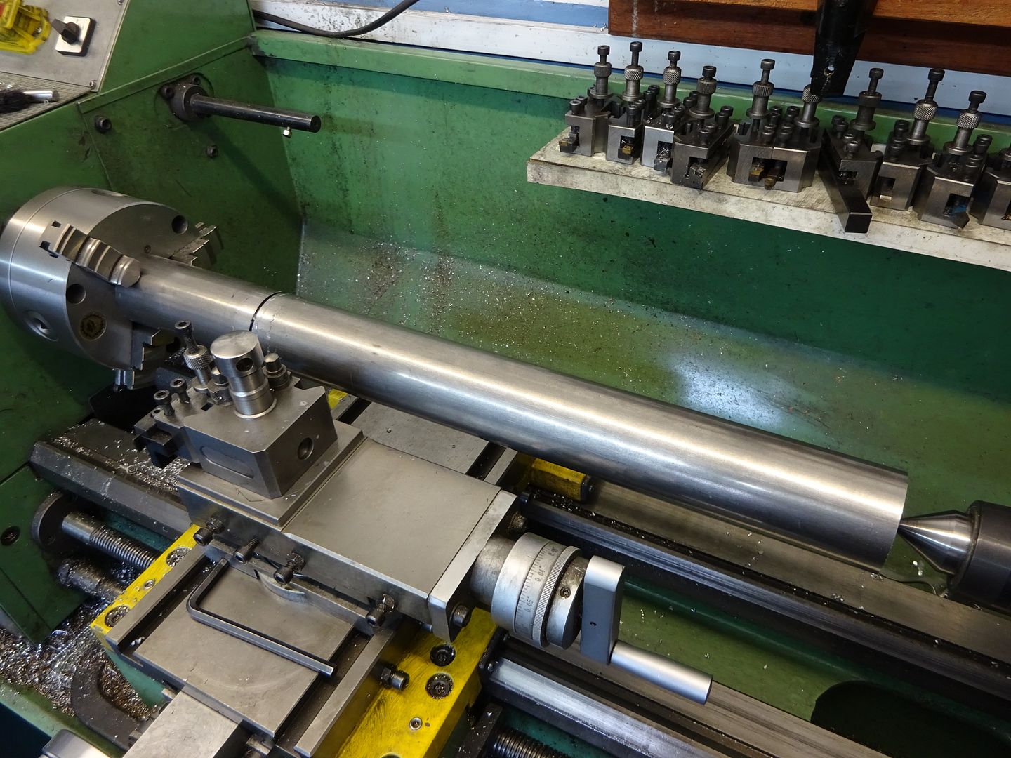
| Andrew Johnston | 22/06/2023 08:03:00 |
 7061 forum posts 719 photos | Posted by Hopper on 22/06/2023 07:47:40:
...centre drill the end and put a tailstock centre in place to stabilise it...
Like this, on a 3.5" diameter workpiece mounted on an homemade expanding mandrel:
Andrew |
| Maurits van Dueren | 22/06/2023 08:18:52 |
| 22 forum posts 2 photos | Have no steadyrest. Have no 4-chuck. Can't centre drill, as the 46mm piece is also 25mm hollow. I did start yesterday making a sort of bull-nose adapter cone for my live centre, but did not try using it yet, as it got late. I guess I will use the bullnose anyway, even if only see the difference, but I think I need to go for the rear-post as default parting option anyway. Mind you, the steady/centre/bullnose and the rear post address different problems. One addresses stability of the part, the other of the tool, so they may at times both be needed. |
| JasonB | 22/06/2023 08:27:23 |
25215 forum posts 3105 photos 1 articles | You can just make a stepped disc to fit into the hole and put a centre drilled hole into that
Also if teh work can be turned around so the groove is at the chuck end that will help
|
 advocated setting the tool above centre height. As machines have improved, this advice has disappeared, but it shouldn't be forgotten. I'll now answer my question...

Please login to post a reply.
Magazine Locator
Want the latest issue of Model Engineer or Model Engineers' Workshop? Use our magazine locator links to find your nearest stockist!
Sign up to our Newsletter
Sign up to our newsletter and get a free digital issue.
You can unsubscribe at anytime. View our privacy policy at www.mortons.co.uk/privacy
Latest Forum Posts
- hemingway ball turner
04/07/2025 14:40:26 - *Oct 2023: FORUM MIGRATION TIMELINE*
05/10/2023 07:57:11 - Making ER11 collet chuck
05/10/2023 07:56:24 - What did you do today? 2023
05/10/2023 07:25:01 - Orrery
05/10/2023 06:00:41 - Wera hand-tools
05/10/2023 05:47:07 - New member
05/10/2023 04:40:11 - Problems with external pot on at1 vfd
05/10/2023 00:06:32 - Drain plug
04/10/2023 23:36:17 - digi phase converter for 10 machines.....
04/10/2023 23:13:48 - More Latest Posts...
- View All Topics
Support Our Partners


Shopping Partners
Subscription Offer

Latest "For Sale" Ads
- Reeves** - Rebuilt Royal Scot by Martin Evans
by John Broughton
£300.00 - BRITANNIA 5" GAUGE James Perrier
by Jon Seabright 1
£2,500.00 - Drill Grinder - for restoration
by Nigel Graham 2
£0.00 - WARCO WM18 MILLING MACHINE
by Alex Chudley
£1,200.00 - MYFORD SUPER 7 LATHE
by Alex Chudley
£2,000.00 - More "For Sale" Ads...
Latest "Wanted" Ads
- D1-3 backplate
by Michael Horley
Price Not Specified - fixed steady for a Colchester bantam mark1 800
by George Jervis
Price Not Specified - lbsc pansy
by JACK SIDEBOTHAM
Price Not Specified - Pratt Burnerd multifit chuck key.
by Tim Riome
Price Not Specified - BANDSAW BLADE WELDER
by HUGH
Price Not Specified - More "Wanted" Ads...
Get In Touch!
Do you want to contact the Model Engineer and Model Engineers' Workshop team?
You can contact us by phone, mail or email about the magazines including becoming a contributor, submitting reader's letters or making queries about articles. You can also get in touch about this website, advertising or other general issues.
Click THIS LINK for full contact details.
For subscription issues please see THIS LINK.
Digital Back Issues


Donate

 Register
 Log-in
Model Engineer Magazine
- Percival Marshall
- M.E. History
- LittleLEC
- M.E. Clock

ME Workshop
- An Adcock
- & Shipley
- Horizontal
- Mill

Subscribe Now
- Great savings
- Delivered to your door

Pre-order your copy!
- Delivered to your doorstep!
- Free UK delivery!
All Forum Topics > Beginners questions > Groove/cutoff tools wants to dig in too much