Forum sponsored by:

Postman Cometh Part 2
Build progress of Stuart No.4
| GarryC | 01/09/2015 16:52:19 |
 740 forum posts 1043 photos | Hi Nick I found that a lot of heat is generated very quickly with gunmetal and it helped to try and keep things as cool as possible as the snatching seemed to 'especially want' to happen when hot, I took my time and let things cool between each drill bit - still managed to burn my finger last time though as I remember. It was something Jason said to watch out for at the time - as usual it was very good advice.. Hope it goes well.. Cheers Garry Edited By Garry_C on 01/09/2015 17:18:44 |
| Michael Gilligan | 01/09/2015 17:47:12 |
 23121 forum posts 1360 photos | Having negligble experience of these steamy devices ... A question if I may: Would it be wise [and/or common practice] to insert a thin shim between the halves before boring? MichaelG. [happy to be ridiculed or educated] |
| JasonB | 01/09/2015 17:59:40 |
 25215 forum posts 3105 photos 1 articles | I've never shimmed model bearings, Its done quite often on the full size hit & miss engines though with either bronze or white metal bearings. My thoughts are that we are not going to be running them lots and if they should wear then the mating "flat" areas are small enough to be rubbed on a sheet of Emery to remove a little metal if you needed to close up the hole. I usually solder mine together before boring so you will get a slight gap once they are melted apart and the solder cleaned off. As Nick's No 4 does not use a separate top half of the bearing and bearing cap the only way to close up any gap would be to pack up the lower bearing. I prefer to have separate caps that are clear of the bearing housing when the bearing is in place so they can close up any gap in the bearing in future.
J |
| Nick_G | 01/09/2015 19:19:37 |
 1808 forum posts 744 photos | . Cheers for the replies guy's Michael. - I understand your logic regarding the shims and I it's a fair point. Jason and Garry. - Thanks for the information. My plan is (please tell me if its a good one or not) is to mount the soleplate with just the bearing bottoms fitted. Then with a piece of precision ground 12mm stock in the collet holder adjust the mill bed until I can just feel contact on both bearing bottoms with a feeler guage. Remove the 12mm stock and using the DRO I have fitted to the mill subtract the width of the feeler guage. Then subtract an additional 6mm to hopefully bring the center of the mill over the line of the bearing split. Pop on the caps and then sally forth. Good plan or a disaster in the making.? Cheers again, Nick |
| JasonB | 01/09/2015 19:23:20 |
25215 forum posts 3105 photos 1 articles | Sounds like you need to get yourself an edge finder or a centre finder/sticky pin to pick up the joint J
PS have you sorted out your DRO problem yet? |
| Nick_G | 01/09/2015 19:33:27 |
1808 forum posts 744 photos | Posted by JasonB on 01/09/2015 19:23:20:
Sounds like you need to get yourself an edge finder or a centre finder/sticky pin to pick up the joint J
PS have you sorted out your DRO problem yet? . My thoughts are that if I use the 12mm PGB that I could also check the vertical alignment of both bearings is good. I don't think my edge finders are long enough to do that with the lower mounted one. Suppose I could use the laser one. Yes, DRO problem sorted. That was down to the idiot that installed it not doing a finished job. - Now I wonder who that was. Nick Edited By Nick_G on 01/09/2015 19:34:24 |
| JasonB | 01/09/2015 19:40:06 |
25215 forum posts 3105 photos 1 articles | If you don't have a decent angle plate to mount the casting to then thats probably your best bet of getting the two bearings vertical. J |
| Gas_mantle. | 01/09/2015 20:15:11 |
 359 forum posts 269 photos | Nice work Nick, I'll look forward to following this thread Peter. |
| Nick_G | 02/09/2015 09:21:20 |
1808 forum posts 744 photos | . Thank you Peter. Work on the bearings has had to take a break for a couple of days. This is due to me being a numptie and not being in possession of a 4BA tap to hold the caps down. So I hope Messers Chronos dispatch the ordered one pronto. Nick |
| mechman48 | 02/09/2015 15:28:51 |
 2947 forum posts 468 photos | M3.5 / M4 would've been the nearest equivalent taps if you were stuck... ?
George.
|
| JasonB | 02/09/2015 16:12:12 |
25215 forum posts 3105 photos 1 articles | Probably best to stick with 4BA then you can use the supplied nuts & studs, Nice chart, where have I seen that before |
| mechman48 | 02/09/2015 19:15:46 |
2947 forum posts 468 photos | Hmmm let me think ... |
| Nick_G | 02/09/2015 23:22:31 |
1808 forum posts 744 photos | . Cheers mechman, But as Jason says I have the studs and I have ordered the HSS taps now. I also really need to replace the existing BA taps I have with HSS ones also. I was very lucky I did not snap the cheep carbon steel ones I bought when building the James Coombes off in castings a couple of times. Nick |
| Nick_G | 07/09/2015 19:25:39 |
1808 forum posts 744 photos | . I have been waiting for some tools to be delivered. (still not arrived today So I spent a bit of time over the weekend making a few tools that I will need. I need at some point to drill and face off the standard. This is quite close to other parts of the casting so I would not be able to do it with standard bits of kit. I therefore turned some scrap drilled and reamed the ends to accept such. These were locktited in as they will not be required to be a long lasting service item. The milling bit and drill were held in the tailstock to ensure they went in reasonably straight.
This is what they are needed for. :-
Also made some T nuts to take some M8 fixings that will be required later. (the ones I already have take M10)
The fly wheel is 5in dia (or hopefully will be
Nick |
| JasonB | 07/09/2015 19:46:20 |
25215 forum posts 3105 photos 1 articles | You may find that milling cutter gets a bit lively when you try to use it that far out of the chuck, what you really need to make is a reverse spot facer, easily filed up from a bit of Silver steel, hardened and then clamped onto your drill bit.
Can you not use the 4-jaw to hold the flywheel by the inside of the rim? You can usually fit a six spoke in OK |
| Nick_G | 08/09/2015 07:34:49 |
1808 forum posts 744 photos | . Hi Jason, That is an inovative way of doing it by reversing the casting. I would never have thought of that. I have though done it before I posted that image and your response. I was mindful of possible chatter but I just had to spot face not cut into a fillet of the casting as you have done. It went OK, but if I had material at an angle to remove I would I think have had problems. Your method is going into filing cabinet in my bonce for future use though. I did consider the 4 jaw for the fly wheel as you suggest, but I think I will be more confident with the faceplate method. Thanks, Nick |
| JasonB | 08/09/2015 07:45:59 |
25215 forum posts 3105 photos 1 articles | Same cutter can be used the right way round fixed to an extended drill or bit of rod so you have a spigot that locates in the hole much like an off the shelf counterbore. I'd also slip a bit of MDF or ply between your ali plate and the flywheel, that way you can machine right across the rim without scoring that nice shiny new plate Edited By JasonB on 08/09/2015 07:47:41 |
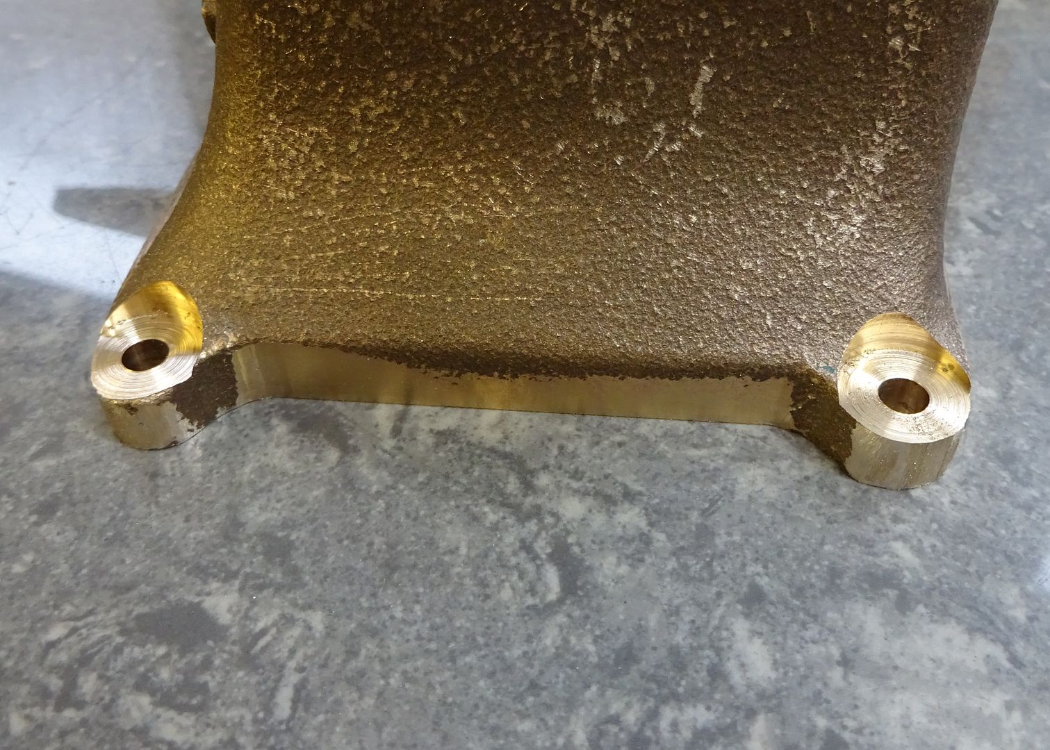
| Nick_G | 30/10/2015 22:46:33 |
1808 forum posts 744 photos | . Hello again folks. It's been a while since I did any work on the No.4. Hopefully I can now get back into the swing of it after my little interlude of making some parts for my mates motorbike turbo conversion. Work has also got in the way of things amongst other distractions. I don't know how others drop straight back into a project. But I find it takes me a few sessions to remember where I was and my plan of attack. Anyway. Decided to finish the main bearings. So they were mounted onto the milling table and drilled out in stages. I did ream to final size but forgot to photograph.
Then onto machining the flywheel. I decided to use the faceplate method.
I drilled and tapped some holes to fix the flywheel and mounted it with some ali spacers behind. There was an inconsiderate blow hole that reared it's ugly head while facing one of the sides.
Resharpened the tool for the final cuts and while it was in the lathe gave it a polish that if had been witnesses by the safety Nazi's would have caused outrage.
Flipped it over and skimmed and polished the other side face.
In the morning I will decide what part I shall puzzle with next. Cheerio, Nick
|
| Nick_G | 01/11/2015 11:00:23 |
1808 forum posts 744 photos | . Con rod time I think.
I have made a sort of split collet out of aluminium so that I can 'hopefully' hold the rod for the rest of the machining jobs. Any other ways of doing such would of course be welcome.
Nick |
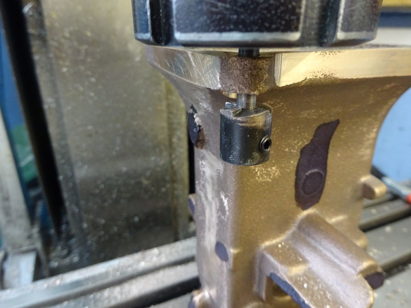
| Nick_G | 04/11/2015 23:03:56 |
1808 forum posts 744 photos | . The bearing was sliced with a slitting saw and then faced each side.
It was then fastened back together with solder and machined into thus :-
Another blast of heat to separate the halves again.
Which just leaves a tad of final dressing and a polish. Nick
|


Please login to post a reply.
Magazine Locator
Want the latest issue of Model Engineer or Model Engineers' Workshop? Use our magazine locator links to find your nearest stockist!
Sign up to our Newsletter
Sign up to our newsletter and get a free digital issue.
You can unsubscribe at anytime. View our privacy policy at www.mortons.co.uk/privacy
Latest Forum Posts
- *Oct 2023: FORUM MIGRATION TIMELINE*
05/10/2023 07:57:11 - Making ER11 collet chuck
05/10/2023 07:56:24 - What did you do today? 2023
05/10/2023 07:25:01 - Orrery
05/10/2023 06:00:41 - Wera hand-tools
05/10/2023 05:47:07 - New member
05/10/2023 04:40:11 - Problems with external pot on at1 vfd
05/10/2023 00:06:32 - Drain plug
04/10/2023 23:36:17 - digi phase converter for 10 machines.....
04/10/2023 23:13:48 - Winter Storage Of Locomotives
04/10/2023 21:02:11 - More Latest Posts...
- View All Topics
Support Our Partners


Shopping Partners
Subscription Offer

Latest "For Sale" Ads
- Reeves** - Rebuilt Royal Scot by Martin Evans
by John Broughton
£300.00 - BRITANNIA 5" GAUGE James Perrier
by Jon Seabright 1
£2,500.00 - Drill Grinder - for restoration
by Nigel Graham 2
£0.00 - WARCO WM18 MILLING MACHINE
by Alex Chudley
£1,200.00 - MYFORD SUPER 7 LATHE
by Alex Chudley
£2,000.00 - More "For Sale" Ads...
Latest "Wanted" Ads
- D1-3 backplate
by Michael Horley
Price Not Specified - fixed steady for a Colchester bantam mark1 800
by George Jervis
Price Not Specified - lbsc pansy
by JACK SIDEBOTHAM
Price Not Specified - Pratt Burnerd multifit chuck key.
by Tim Riome
Price Not Specified - BANDSAW BLADE WELDER
by HUGH
Price Not Specified - More "Wanted" Ads...
Get In Touch!
Do you want to contact the Model Engineer and Model Engineers' Workshop team?
You can contact us by phone, mail or email about the magazines including becoming a contributor, submitting reader's letters or making queries about articles. You can also get in touch about this website, advertising or other general issues.
Click THIS LINK for full contact details.
For subscription issues please see THIS LINK.
Digital Back Issues


Donate

 Register
 Log-in
Model Engineer Magazine
- Percival Marshall
- M.E. History
- LittleLEC
- M.E. Clock

ME Workshop
- An Adcock
- & Shipley
- Horizontal
- Mill

Subscribe Now
- Great savings
- Delivered to your door

Pre-order your copy!
- Delivered to your doorstep!
- Free UK delivery!
All Forum Topics > Work In Progress and completed items > Postman Cometh Part 2