| Paul Major | 30/12/2013 21:45:55 |
53 forum posts
13 photos
| Hi,
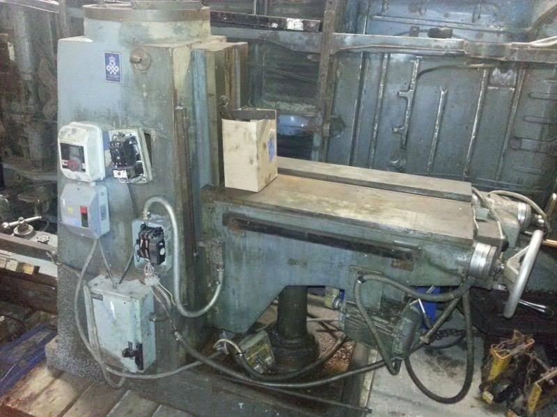
First post on here having aquired my first mill, a Beaver VBRP model from Balding Engineering.
Plan is to use it for "hobby engineering" mainly on engine work, skimming heads, fly cutting cases for aircooled vdubs etc.
Rather large for a hobby mill but managed to squeeze it into the workshop so alls good  . .
Done the research on lathes.co.uk etc but very little written about the Beaver's so thought as well as asking for lots of advice this would be a good way to document how one of these is put together incase anyone else is looking for some info.
Seperated the table and arm to help with transport. Was still a pig too unload using a combination of 1T engine crane and my 3T 4 post ramp to get them out of the trailer. Reckon the main body is about 900kg, arm 300kg and table 100+ 
Got them onto pallets so i can move around the workshop anyways.
Cheers,
Paul.
Edited by JasonB to add images to post
Edited By JasonB on 31/12/2013 07:48:10 |
| Michael Gilligan | 31/12/2013 07:32:41 |

23121 forum posts
1360 photos
| A great first post, Paul
I look forward to following your progress.
MichaelG.
|
| John Haine | 31/12/2013 09:17:57 |
5563 forum posts
322 photos
| Not a mini mill then?
|
| Ian S C | 31/12/2013 11:40:53 |

7468 forum posts
230 photos
| I thought it was a mini mill, you could machine a Mini on it. Ian S C
|
| Mike Clarke | 31/12/2013 11:58:43 |
95 forum posts
2 photos
| Hi Paul - looking forward to seeing it restored.
We used to have a VBRP at my last employer, a beautiful machine.
Regards,
Mike.
|
| Paul Major | 31/12/2013 12:31:41 |
53 forum posts
13 photos
| Posted by Ian S C on 31/12/2013 11:40:53:
I thought it was a mini mill, you could machine a Mini on it. Ian S C
 I know what you mean Ian, it is huge. Was looking for a Centec or Tom Senior but they were way to expensive. This came along at basically what it was worth as scrap value so I thought I would take a punt and see if it could be salvaged. I know what you mean Ian, it is huge. Was looking for a Centec or Tom Senior but they were way to expensive. This came along at basically what it was worth as scrap value so I thought I would take a punt and see if it could be salvaged. 
Paul.
|
| Paul Major | 31/12/2013 12:47:31 |
53 forum posts
13 photos
| Closer view of the electrics.
Plan is to get a rotary converter or digital plug n play inverter to allow me to supply a single 3 phase to the original input allowing all 5 motors plus suds pumpto be run from the one feed as it was originally.
Am also planning to rewire everything at the same time as some of the wiring looks like it is original (circa 1960?).
![[IMG]](http://i1117.photobucket.com/albums/k599/mm289/Workshop/2013-09-22185437_zpsc3c8ba3b.jpg) ![[IMG]](http://i1117.photobucket.com/albums/k599/mm289/Workshop/2013-09-22185428_zps001e12e9.jpg) ![[IMG]](http://i1117.photobucket.com/albums/k599/mm289/Workshop/2013-09-22185424_zps8fccbd17.jpg) ![[IMG]](http://i1117.photobucket.com/albums/k599/mm289/Workshop/2013-09-22185414_zps2764e88c.jpg)
![[IMG]](http://i1117.photobucket.com/albums/k599/mm289/Workshop/2013-09-22185410_zpse3092371.jpg)
Cheers
Paul.
|
| john kennedy 1 | 31/12/2013 12:58:59 |
214 forum posts
24 photos
| I remember we had one where I worked in the 70s. It was used to make carbon electrodes for spark eroding dies to stamp out car crankshafts etc. It had 2 cutting heads and a smaller stylus head for copying from a fibreglass dummy crank. The heads worked in the opposite direction to each other,thereby making a pair of dies.
Got to say its a beautifully well made machine and I wish I had one
|
| Paul Major | 31/12/2013 13:00:11 |
53 forum posts
13 photos
|
Edited By Paul Major on 31/12/2013 13:16:34 |
| Paul Major | 31/12/2013 13:02:15 |
53 forum posts
13 photos
| Glad a few of you chaps have seen/used these before. As a bit of a novice in this area I am sure I will be getting you to rake over your memory banks 
Paul.
|
| Paul Major | 31/12/2013 13:27:05 |
53 forum posts
13 photos
| I mentioned above that it has 5 motors and here they are 
Main motor is a mahoosive twin speed job
![[IMG]](http://i1117.photobucket.com/albums/k599/mm289/Workshop/2013-08-30191005_zps3871f412.jpg)
A Power feed to the knee
![[IMG]](http://i1117.photobucket.com/albums/k599/mm289/Workshop/2013-09-22185320_zpsc76d0806.jpg)
Table feed motor (Y axis).
![[IMG]](http://i1117.photobucket.com/albums/k599/mm289/Workshop/2013-11-17170955_zps42dec284.jpg)
Cross feed motor (rapid return)
![[IMG]](http://i1117.photobucket.com/albums/k599/mm289/Workshop/2013-09-22190203_zps62ac0fed.jpg)
And a second cross feed motor that isn't off this machine but has been modded to fit and provide a slow feed
![[IMG]](http://i1117.photobucket.com/albums/k599/mm289/Workshop/2013-09-22185910_zpsbff1b1f4.jpg)
And finally, down here somewhere is a suds pump 
![[IMG]](http://i1117.photobucket.com/albums/k599/mm289/Workshop/2013-09-22185501_zpsc7d2ea4a.jpg)
Cheers,
Paul.
Edited By Paul Major on 31/12/2013 13:37:25 |
| John Stevenson | 31/12/2013 13:28:43 |

5068 forum posts
3 photos
| Paul,
I have the CNC version of this machine, bottom half is about the same but top half it totally different being a fixed head.
Both these models are built like brick out houses, totally put a Bridgeport to shame, mind you that's not hard to do.
|
| Michael Gilligan | 31/12/2013 13:55:14 |
23121 forum posts
1360 photos
| Posted by Paul Major on 31/12/2013 13:00:11:
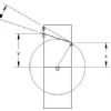
U channels bolted together and ends notched to allow it to sit on main RSJ's
![[IMG]](http://i1117.photobucket.com/albums/k599/mm289/Workshop/2013-11-12182218_zps93bef742.jpg)
![[IMG]](http://i1117.photobucket.com/albums/k599/mm289/Workshop/2013-11-12185738_zps643648d5.jpg)
Any thoughts on whether this will have materially weakened the end of the beam?
Paul,
In principle, that should not make a big difference to the stiffness or strength of the cross beam ... [the T section is almost as good as the back-to-back U sections, provided that it stays vertical] ... but I cannot see how you are preventing it from toppling.
Apologies if I have missed seeing something clever.
MichaelG.
|
| Paul Major | 31/12/2013 14:07:16 |
53 forum posts
13 photos
| Thanks Michael.
Your right in that there isn't anything obvious stopping it from toppling.
In practice though, the fit to the wooden rafters above is quite tight, maybe 5mm, so they stop the beam from rotating. Also once the grider trolley is in place and a load is on this pulls it down "square" so to speak.
I did consider adding a couple of right angles in place to act almost as pads/slides but if the strength isn't compromised then I might try it like it is and see how stable it looks.
Cheers,
Paul.
|
| Michael Gilligan | 31/12/2013 14:13:33 |
23121 forum posts
1360 photos
| Paul,
If you want to do some maths, you can confirm the change in stiffness by comparing the Moments of Inertia for the two shapes.
... Happy Googling
MichaelG.
|
| Paul Major | 31/12/2013 20:26:21 |
53 forum posts
13 photos
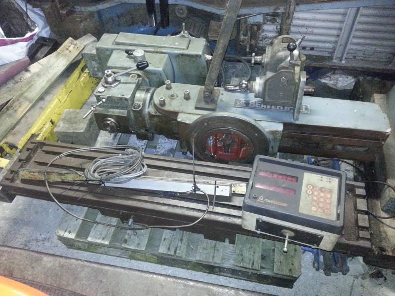
| The next step was to remove the table feed leadscrew. This turned out to be a bit of an epic battle as the parts diagram from the manual I have does not show the gearbox or power feed.
The following sequence shows how it should be done, which I found out kinda by trial and error!
The leadscrew runs right through the gearbox as one piece terminating in the micrometer and handle.
![[IMG]](http://i1117.photobucket.com/albums/k599/mm289/Workshop/2013-09-22185246_zpsf28d551e.jpg)
The leadscrew sits in the side of the knee but will not come out sideways without the removal of a “C” shaped plate, which in turn is held in by bolts which can only be accessed when the gearbox is removed.
This picture shows the leadscrew and the locking nut that holds it in place against the C plate.
![[IMG]](http://i1117.photobucket.com/albums/k599/mm289/Workshop/2013-11-17171810_zpsc7933d76.jpg)
The gear box has interchangeable cogs to alter the rate of feed, only got the two that are fitted in this pic so won't have the full range of speeds to start with.
![[IMG]](http://i1117.photobucket.com/albums/k599/mm289/Workshop/2013-11-17171119_zps37e14554.jpg)
![[IMG]](http://i1117.photobucket.com/albums/k599/mm289/Workshop/2013-11-17171056_zps0284908f.jpg)
This is the parts diagram I was working from.
![[IMG]](http://i1117.photobucket.com/albums/k599/mm289/Workshop/2013-11-21215844_zpsb6f80521.jpg)
First of comes the handle which reveals a large circlip that holds the mic ring on and a securing screw that I presume stops the mic from slipping when it is zero’d.
Initially I couldn’t work out of the mic ring was threaded on, held in by a grub screw or what. As it turns out it just slips over collet, I don’t know if it is supposed to move freely on this collet or not but it was totally seized on.
In the end I loosened off the leadscrew locknut behind the casing to create a small gap between the mic ring and the gearbox. It is important to keep this nut on though otherwise the leadscrew is pulling just against the "Hoffman bearing" and will break it.
![[IMG]](http://i1117.photobucket.com/albums/k599/mm289/Workshop/2013-11-21214325_zps7265636c.jpg)
![[IMG]](http://i1117.photobucket.com/albums/k599/mm289/Workshop/2013-11-17175428_zpsee0d8315.jpg)
I then used a couple of small drifts and applied some heat to the dial and it seemed to make a bit of progress so out came the biggest bearing puller I have in the workshop.
![[IMG]](http://i1117.photobucket.com/albums/k599/mm289/Workshop/2013-11-21212326_zps26706408.jpg)
And it started moving
![[IMG]](http://i1117.photobucket.com/albums/k599/mm289/Workshop/2013-11-21212331_zps53cc1e71.jpg)
After a fair bit of working back and forward the dial eventually came off. It is an interference fit that is locked in place by a pin/screw that goes in through the front of the dial. This pin then pushes a ball bearing up to lock the dial in place. Even though I had removed the pin the dial had rusted onto the collar and hence why I had the problem removing it.
This ball bearing needs to be removed to reveal a very small grub screw which I will talk about in a moment.
Cheers,
Paul.
Edited By Paul Major on 31/12/2013 20:34:25 |
| Graham Wharton | 31/12/2013 20:33:19 |
149 forum posts
48 photos
| Nice work Paul. Look forward to seeing how it turns out. I hope to do a similar size refurb on an old beaver or bridgeport when I get more space.
Just a comment about your plans to hook up to a 3 phase supply generated by an electronic inverter. I believe these can only be used to power a single motor at a time. The instruction manual in mine says to wire directly from inverter to single motor, and not via any switchgear at all. You might want to look into this before committing to any big inverter purchases.
I think a rotary converter would be fine for multiple motors.
Graham
|
| John Stevenson | 31/12/2013 20:34:35 |
5068 forum posts
3 photos
| Paul,
You are going to need a rotary converter for that machine as you can't run a two speed motor off a 240v in 240v out inverter.
Also the knee motor isn't a power feed motor as such as it's just on or off and one speed, no reason though why you should not fit an inverter to this axis though to give you a vertical feed for boring etc as you only have 5" on quill.
having said that do you have 5" on this model or 6" ?
|
| Paul Major | 31/12/2013 20:39:16 |
53 forum posts
13 photos
| Thanks Graham,
Yep, your right a normal inverter/VFD will only run one motor. You can however get digital inverters which are "plug and play" that allow the running of multiple motors from the one inverter,
Naturally they are far more expensive! The Drives Direct 7.5hp one is about £1300 I think.  The alternative is a rotary converter. The alternative is a rotary converter.
Cheers,
Paul.
|
| Paul Major | 31/12/2013 23:38:00 |
53 forum posts
13 photos
| Once the mic ring is removed this then allows you to get to a tapered pin, which locks the collar in place that the dial is mounted on.
![[IMG]](http://i1117.photobucket.com/albums/k599/mm289/Workshop/2013-11-21213752_zps421257d4.jpg)
At this point it gets a bit confusing as the collar needs to come over the end of the leadscrew, (yellow arrow) but the end looks like it has a mushroom head (red circle) that stops the handle engagement collar sliding off.
![[IMG]](http://i1117.photobucket.com/albums/k599/mm289/Workshop/2013-11-21213752v2_zps36da9f41.jpg)
![[IMG]](http://i1117.photobucket.com/albums/k599/mm289/Workshop/2013-11-23133528_zps4d6fe995.jpg)
Initially I ground off the mushroom head to allow me to removed the engagement collar, but eventually found this was unnecessary.
![[IMG]](http://i1117.photobucket.com/albums/k599/mm289/Workshop/2013-12-01160446_zps4ac76563.jpg)
After again using drifts and brute force I managed to get the collar to move and when it did it revealed that mushroom head is actually a sleeve that fits over the end of the leadscrew.
To remove the collar from this sleeve you need to remove the grub screw that is located BENEATH the mic ring locking ball bearing mentioned above.
![[IMG]](http://i1117.photobucket.com/albums/k599/mm289/Workshop/2013-12-01172731_zps089f5a44.jpg)
This then allows the collar/sleeve to slide off the leadscrew (in theory, again mine were seized solid).
![[IMG]](http://i1117.photobucket.com/albums/k599/mm289/Workshop/2013-12-01172628_zps695104f7.jpg)
![[IMG]](http://i1117.photobucket.com/albums/k599/mm289/Workshop/2013-12-01172643_zps09396043.jpg)
![[IMG]](http://i1117.photobucket.com/albums/k599/mm289/Workshop/2013-12-01173146_zps979484d8.jpg)
With the collets removed the gearbox cover will then slide off.
![[IMG]](http://i1117.photobucket.com/albums/k599/mm289/Workshop/2013-12-01173353_zpscd2da7a2.jpg)
![[IMG]](http://i1117.photobucket.com/albums/k599/mm289/Workshop/2013-12-01173409_zpse1b3227b.jpg)
Cheers,
Paul.
|

![[IMG]](http://s1117.photobucket.com/user/mm289/media/Workshop/2013-09-22185437_zpsc3c8ba3b.jpg.html)
![[IMG]](http://s1117.photobucket.com/user/mm289/media/Workshop/2013-09-22185428_zps001e12e9.jpg.html)
![[IMG]](http://s1117.photobucket.com/user/mm289/media/Workshop/2013-09-22185424_zps8fccbd17.jpg.html)
![[IMG]](http://s1117.photobucket.com/user/mm289/media/Workshop/2013-09-22185414_zps2764e88c.jpg.html)
![[IMG]](http://s1117.photobucket.com/user/mm289/media/Workshop/2013-09-22185410_zpse3092371.jpg.html)

![[IMG]](http://s1117.photobucket.com/user/mm289/media/Workshop/2013-11-12182144_zpsc726f825.jpg.html)
, off I went to the local steel fabricator to see what he had lying around. Didn't have a long enough piece of 100mm UC but had 6m of 100mm channel for £60 which seemed reasonable so have used that and am going to bolt back to back to make up an H shape.
![[IMG]](http://s1117.photobucket.com/user/mm289/media/Workshop/2013-11-12182242_zpsb12612e3.jpg.html)
![[IMG]](http://s1117.photobucket.com/user/mm289/media/Workshop/2013-11-12182218_zps93bef742.jpg.html)
![[IMG]](http://s1117.photobucket.com/user/mm289/media/Workshop/2013-11-12185738_zps643648d5.jpg.html)
![[IMG]](http://s1117.photobucket.com/user/mm289/media/Workshop/2013-11-12190416_zps9e32d1f2.jpg.html)

![[IMG]](http://s1117.photobucket.com/user/mm289/media/Workshop/2013-08-30191005_zps3871f412.jpg.html)
![[IMG]](http://s1117.photobucket.com/user/mm289/media/Workshop/2013-09-22185320_zpsc76d0806.jpg.html)
![[IMG]](http://s1117.photobucket.com/user/mm289/media/Workshop/2013-11-17170955_zps42dec284.jpg.html)
![[IMG]](http://s1117.photobucket.com/user/mm289/media/Workshop/2013-09-22190203_zps62ac0fed.jpg.html)
![[IMG]](http://s1117.photobucket.com/user/mm289/media/Workshop/2013-09-22185910_zpsbff1b1f4.jpg.html)
![[IMG]](http://s1117.photobucket.com/user/mm289/media/Workshop/2013-09-22185501_zpsc7d2ea4a.jpg.html)
![[IMG]](http://s1117.photobucket.com/user/mm289/media/Workshop/2013-09-22185246_zpsf28d551e.jpg.html)
![[IMG]](http://s1117.photobucket.com/user/mm289/media/Workshop/2013-11-17171810_zpsc7933d76.jpg.html)
![[IMG]](http://s1117.photobucket.com/user/mm289/media/Workshop/2013-11-17171119_zps37e14554.jpg.html)
![[IMG]](http://s1117.photobucket.com/user/mm289/media/Workshop/2013-11-17171056_zps0284908f.jpg.html)
![[IMG]](http://s1117.photobucket.com/user/mm289/media/Workshop/2013-11-21215844_zpsb6f80521.jpg.html)
![[IMG]](http://s1117.photobucket.com/user/mm289/media/Workshop/2013-11-21214325_zps7265636c.jpg.html)
![[IMG]](http://s1117.photobucket.com/user/mm289/media/Workshop/2013-11-17175428_zpsee0d8315.jpg.html)
![[IMG]](http://s1117.photobucket.com/user/mm289/media/Workshop/2013-11-21212326_zps26706408.jpg.html)
![[IMG]](http://s1117.photobucket.com/user/mm289/media/Workshop/2013-11-21212331_zps53cc1e71.jpg.html)
![[IMG]](http://s1117.photobucket.com/user/mm289/media/Workshop/2013-11-21213752_zps421257d4.jpg.html)
![[IMG]](http://s1117.photobucket.com/user/mm289/media/Workshop/2013-11-21213752v2_zps36da9f41.jpg.html)
![[IMG]](http://s1117.photobucket.com/user/mm289/media/Workshop/2013-11-23133528_zps4d6fe995.jpg.html)
![[IMG]](http://s1117.photobucket.com/user/mm289/media/Workshop/2013-12-01160446_zps4ac76563.jpg.html)
![[IMG]](http://s1117.photobucket.com/user/mm289/media/Workshop/2013-12-01172731_zps089f5a44.jpg.html)
![[IMG]](http://s1117.photobucket.com/user/mm289/media/Workshop/2013-12-01172628_zps695104f7.jpg.html)
![[IMG]](http://s1117.photobucket.com/user/mm289/media/Workshop/2013-12-01172643_zps09396043.jpg.html)
![[IMG]](http://s1117.photobucket.com/user/mm289/media/Workshop/2013-12-01173146_zps979484d8.jpg.html)
![[IMG]](http://s1117.photobucket.com/user/mm289/media/Workshop/2013-12-01173353_zpscd2da7a2.jpg.html)
![[IMG]](http://s1117.photobucket.com/user/mm289/media/Workshop/2013-12-01173409_zpse1b3227b.jpg.html)


 Register
 Log-in

