Forum sponsored by:

Inserted cross slide feed nuts
How to remove?
| Andy Carlson | 23/06/2020 18:28:24 |
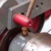
| 440 forum posts 132 photos | I'm not sure if Faircut used a design similar to other lathes but so far my searching hasn't turned up anything similar. The nut is a non ferrous insert into the saddle (the compound and tailstock barrel have a similar arrangement). A slotted grub screw bears on the insert. I've got the screw out (it broke a bit) but I'm not much wiser. A straight pull with the leadscrew showed no sign of shifting it. The lack of concentricity on the cross slide insert suggests it may be threaded but getting anything to turn it will take some thinking. The compound insert doesn't show such noticeable eccentricity. I can speculate on how to shift it (or drill it out) but I'm hoping that someone has seen something similar and can give me some clues.
|
| old mart | 23/06/2020 19:15:13 |
| 4655 forum posts 304 photos | At a guess, it is merely pressed in. You should measure both ends just in case there is a shoulder, otherwise some sort of puller should be made, or use a press if you have one. If you are still concerned about the possibility of it being screwed in, then either turn up a piece of metal that just fits the bore nicely, with an end the same size as the interface between the bronze and cast iron. That would prove the presence or absence of a thread. You could also measure the interface diameter at several angles to see if it is round or not. |
| Andy Carlson | 23/06/2020 20:14:22 |
| 440 forum posts 132 photos | The other end is quite deeply recessed in the casting so it's not possible to do any useful measurements there (same on the compound). The cross slide insert is pretty convincingly non circular... which would suggest the start of a thread but the situation with the compound is not so clear. I have a theory that Faircut liberally borrowed ideas from other lathe makers so I'm hoping that someone will say 'ah, that's exactly like the XYZ lathe'. |
| Brian Morehen | 23/06/2020 20:18:02 |
 191 forum posts 11 photos | Hi Andy , Your insert is so close to the bottom of your cross slide ,Just like mine was at the top which was why I made my replacement the way I did fear of breaking the top of my cross slide , Yours very little room to play with i will watch this operation of yours with interest. I wonder if this has just been pressed in does not like this could have been screwed in . Before i had a lathe. I had a small pulley made for a motor when collected was told this will not fit your motor shaft . Put the motor in the freezer for 24 Hrs Then push the pulley on do not use for 24 Hrs . This I did and it ran for years without any further problem the machine was eventually scrapped with the motor still OK Good luck Brian |
| Andy Carlson | 23/06/2020 20:25:23 |
| 440 forum posts 132 photos | It was upside down when I took the photo but I take your point If it is pressed in then I struggle to see why it would be worth having a grub screw but who knows. |
| old mart | 23/06/2020 20:39:44 |
| 4655 forum posts 304 photos | You mention the deep recessing of the other end, I would then expect any threads in the cast iron to be visible. The only time I have seen nuts like this in threaded housings is if there are two in the hole and there is backlash adjustment. The Smart & Brown model A tailstock has screwed in nuts to Adjust the backlash. There are slots in the outer nut to turn it. Edited By old mart on 23/06/2020 20:40:12 |
| DiogenesII | 23/06/2020 20:49:42 |
| 859 forum posts 268 photos | ..well, if iti helps to provoke discussion, maybe they fitted plain slugs and secured them with a grubscrew, and then spotted the thread-centre through the leadscrew brackets after they were fitted-up, in order to ensure alignment.. ..wouldn't be odd for them to come out a bit off-centre.. If they are pressed in, they'd still have to be positively located by a screw/pin/collar to resist the thrust of the screw causing "creep".. . |
| Pete Rimmer | 23/06/2020 20:49:46 |
| 1486 forum posts 105 photos | Posted by Andy Carlson on 23/06/2020 18:28:24: The lack of concentricity on the cross slide insert suggests it may be threaded but getting anything to turn it will take some thinking. The compound insert doesn't show such noticeable eccentricity. If the hole is blind I'd pump it full of grease and wind the screw into it. If it's a through-hole I'd wind the screw right in then punch it out with an aluminium drift against the end of the screw. |
| Andy Carlson | 23/06/2020 21:17:31 |
| 440 forum posts 132 photos | Posted by old mart on 23/06/2020 20:39:44:
You mention the deep recessing of the other end, I would then expect any threads in the cast iron to be visible. The only time I have seen nuts like this in threaded housings is if there are two in the hole and there is backlash adjustment. The Smart & Brown model A tailstock has screwed in nuts to Adjust the backlash. There are slots in the outer nut to turn it. Edited By old mart on 23/06/2020 20:40:12 That's a good idea. At the moment it's all darkness and decades of crud on t'other side but I shall give it a clean and see what turns up. I doubt there is anything so clever as backlash adjustment going on here. |
| Andy Carlson | 23/06/2020 21:21:24 |
| 440 forum posts 132 photos | Posted by DiogenesII on 23/06/2020 20:49:42:
..well, if iti helps to provoke discussion, maybe they fitted plain slugs and secured them with a grubscrew, and then spotted the thread-centre through the leadscrew brackets after they were fitted-up, in order to ensure alignment.. ..wouldn't be odd for them to come out a bit off-centre.. If they are pressed in, they'd still have to be positively located by a screw/pin/collar to resist the thrust of the screw causing "creep".. . Hmm... an interesting point... which suggests that I'd need to do the same when making a new one (which is of course the point of all of this). So some sort of transfer punch type of arrangement and then drill and tap (square thread
|
| Andy Carlson | 23/06/2020 21:29:53 |
| 440 forum posts 132 photos | Posted by Pete Rimmer on 23/06/2020 20:49:46:
If the hole is blind I'd pump it full of grease and wind the screw into it. If it's a through-hole I'd wind the screw right in then punch it out with an aluminium drift against the end of the screw. Not blind. It will need a shouldered punch making up I think. The surviving threads in the saddle insert are paper thin and wont take that sort of force... but no point beating away at a punch if it's threaded so I need to be as sure as I can on the answer to that question first. Happily both the cross slide and compund screws are 3/8 inch so hopefully I only need to make one tool. BTW, the saddle in the photo is a 'spare'. The one that belongs to my lathe should have less wear but I'm not intending to mess with it until I know that I can make this work on the 'spare'. |
| Jouke van der Veen | 23/06/2020 21:50:54 |
| 203 forum posts 19 photos | Andy, There is a solution of thread repair by drilling out the original diameter, tapping a larger diameter thread and placing an insert. If it is allowd to mention trade names: Helicoil applies an insert which is some kind of shaped wire that follows the new tapped thread. Time-Sert applies a thin walled solid insert of which internal thread and external thread have the same pitch. The latter seems to me more suitable for thread repair where the spindle has to move more or less freely. You need special tooling to place the insert and there is also a tool to replace an insert which means that, once you tapped the larger diameter thread, you can easily replace the insert when it is worn. I have not seen inserts made from brass or bronze. I have thought of repairing the thread for the spindle in my Emco Compact 5 saddle with a Time-Sert insert. Edited By Jouke van der Veen on 23/06/2020 21:52:01 Edited By Jouke van der Veen on 23/06/2020 21:56:07 |
| Robert Butler | 23/06/2020 22:06:41 |
| 511 forum posts 6 photos | Not much room for an insert. Robert Butler |
| Andy Carlson | 23/06/2020 22:07:32 |
| 440 forum posts 132 photos | Thanks. This insert is definitely original rather than a later repair - I have two cross slides, two compounds and two tailstocks which have come from lathes at the opposite ends of the country and they all have the same arrangement. I guess that helicoils may have been in the back of my mind when I wondered if these inserts are threaded both outside and inside but the possibility that the inside hole was made in situ and may not be concentric is one that I had not considered until this evening. Definitely a job where it is worth spending plenty of time thinking and asking questions before starting. Edited By Andy Carlson on 23/06/2020 22:08:40 |
| Nigel Graham 2 | 24/06/2020 00:08:17 |
| 3293 forum posts 112 photos | " The other end is quite deeply recessed in the casting so it's not possible to do any useful measurements there (same on the compound). " My trick for measuring awkward recesses and holes is to use the shanks of drills or milling-cutters, or other suitable round items, as plug-gauges. To measure the depth down to the insert if it does not have much rim showing, you could wind the leadscrew in until its end arrives flush with the end of the insert, so giving plenty of land for a depth-micrometer or the tail of a vernier / digital caliper. That may also help show if the insert is down against a shoulder within the casting. |
| Andy Carlson | 24/06/2020 07:52:20 |
| 440 forum posts 132 photos | Thanks. A close inspection (...or as close as I can get) of the less accessible side of the inserts is definitely on the agenda for today. Hopefully it will help me to figure out whether the thing is threadded or pressed in. |
| not done it yet | 24/06/2020 08:16:07 |
| 7517 forum posts 20 photos | Posted by Andy Carlson on 23/06/2020 22:07:32:
Thanks. This insert is definitely original rather than a later repair - I have two cross slides, two compounds and two tailstocks which have come from lathes at the opposite ends of the country and they all have the same arrangement. I guess that helicoils may have been in the back of my mind when I wondered if these inserts are threaded both outside and inside but the possibility that the inside hole was made in situ and may not be concentric is one that I had not considered until this evening. Definitely a job where it is worth spending plenty of time thinking and asking questions before starting. Edited By Andy Carlson on 23/06/2020 22:08:40 Time to choose just one of these (spare) items, carefully align and mill out the insert carefully to full diameter of the parent hole (core diameter if that is appropriate). It will soon become apparent whether there is, indeed a thread in there if helical stripes of metal become visible in the hole. I wrote ‘mill’, not ‘drill’, specifically. Inspecting the bottom of the grub screw hole might also be enlightening? added to edit. Another alternative might be to securely loctite a bolt in the thread and apply a large spanner when at full strength? Edited By not done it yet on 24/06/2020 08:19:17 |
| SillyOldDuffer | 24/06/2020 09:18:51 |
| 10668 forum posts 2415 photos | Just some guesses! As the thread takes a fair amount of stress as the saddle is worked, I believe it must be well fixed. I don't think there's enough room for another thread. So I suspect a shrink fit, ie a tight insert was forced into a hot saddle sized to give a really strong friction grip when the saddle cooled down. In which case it will have to be bored out. Another possibility is age related corrosion. This can be better than superglue, and the grub-screw being damaged removing it could be a clue! Heat cycling is a good way of breaking gunged up joints, plus penetrating oil. I suspect the grub-screw is a crude backlash adjuster, not a fixing. As the insert wears, the grub might be tightened to crush the insert down on the leadscrew. If so, the deformation would also make it hard to get the insert out. Dave Edited By SillyOldDuffer on 24/06/2020 09:19:55 |
| Michael Gilligan | 24/06/2020 10:13:29 |
 23121 forum posts 1360 photos | Warning: This suggestion may cause outrage amongst conservators Mill away the cast iron and the insert [inspecting and photographing as you proceed], in the manner of an archaeological excavation. This will provide clear evidence of the original construction and a convenient recess in which to fit a bespoke replacement. MichaelG. . This recent thread may be relevant to to selection of a suitable cutter, if you prefer to avoid creating stress-raisers. https://www.model-engineer.co.uk/forums/postings.asp?th=162127&p=3 Edited By Michael Gilligan on 24/06/2020 10:22:51 |
| Robert Atkinson 2 | 24/06/2020 10:21:25 |
 1891 forum posts 37 photos | The edge of the casting adjacent to the bush at the 10:00 to 11:00 position looks like it is proud of the surface like the start of a thread being pushed out. This might mean it is threaded. As this is a spare I'd suggest a semi-destructive investigation. If you have a mill start to cut away the end of the bush at it's thickest point. Use an end mill bigger than the thickness of the bush but less than half th diameter. It should be obvious if there is a thread as ou will hit cast iron. A drill or even slitting at an angle with a hacksaw blade (with the height reduced by grinding) would also do. Robert G8RPI. |


Please login to post a reply.
Magazine Locator
Want the latest issue of Model Engineer or Model Engineers' Workshop? Use our magazine locator links to find your nearest stockist!
Sign up to our Newsletter
Sign up to our newsletter and get a free digital issue.
You can unsubscribe at anytime. View our privacy policy at www.mortons.co.uk/privacy
Latest Forum Posts
- hemingway ball turner
04/07/2025 14:40:26 - *Oct 2023: FORUM MIGRATION TIMELINE*
05/10/2023 07:57:11 - Making ER11 collet chuck
05/10/2023 07:56:24 - What did you do today? 2023
05/10/2023 07:25:01 - Orrery
05/10/2023 06:00:41 - Wera hand-tools
05/10/2023 05:47:07 - New member
05/10/2023 04:40:11 - Problems with external pot on at1 vfd
05/10/2023 00:06:32 - Drain plug
04/10/2023 23:36:17 - digi phase converter for 10 machines.....
04/10/2023 23:13:48 - More Latest Posts...
- View All Topics
Support Our Partners


Shopping Partners
Subscription Offer

Latest "For Sale" Ads
- Reeves** - Rebuilt Royal Scot by Martin Evans
by John Broughton
£300.00 - BRITANNIA 5" GAUGE James Perrier
by Jon Seabright 1
£2,500.00 - Drill Grinder - for restoration
by Nigel Graham 2
£0.00 - WARCO WM18 MILLING MACHINE
by Alex Chudley
£1,200.00 - MYFORD SUPER 7 LATHE
by Alex Chudley
£2,000.00 - More "For Sale" Ads...
Latest "Wanted" Ads
- D1-3 backplate
by Michael Horley
Price Not Specified - fixed steady for a Colchester bantam mark1 800
by George Jervis
Price Not Specified - lbsc pansy
by JACK SIDEBOTHAM
Price Not Specified - Pratt Burnerd multifit chuck key.
by Tim Riome
Price Not Specified - BANDSAW BLADE WELDER
by HUGH
Price Not Specified - More "Wanted" Ads...
Get In Touch!
Do you want to contact the Model Engineer and Model Engineers' Workshop team?
You can contact us by phone, mail or email about the magazines including becoming a contributor, submitting reader's letters or making queries about articles. You can also get in touch about this website, advertising or other general issues.
Click THIS LINK for full contact details.
For subscription issues please see THIS LINK.
Digital Back Issues


Donate

 Register
 Log-in
Model Engineer Magazine
- Percival Marshall
- M.E. History
- LittleLEC
- M.E. Clock

ME Workshop
- An Adcock
- & Shipley
- Horizontal
- Mill

Subscribe Now
- Great savings
- Delivered to your door

Pre-order your copy!
- Delivered to your doorstep!
- Free UK delivery!
All Forum Topics > Manual machine tools > Inserted cross slide feed nuts