Forum sponsored by:

Machining Bevel Gears
| Gary Wooding | 04/05/2014 10:18:10 |
| 1074 forum posts 290 photos | I found the MEW article "Design and CNC Machining of Straight Tooth Bevel Gears" very interesting, but one statement defeated me. On page 14 the author states... "This particular differential has 3 pinions equi-spaced around the gear. It is important that the number of teeth on the gear is divisible by three, with no remainder. Otherwise the three pinions will not sit equally spaced around the gear, each in the same orientation, and will not therefore mate with the second gear wheel." I agree that the number of gear teeth has to be an integral multiple of three in order for the pinions to have the same orientation. But why do they need to have the same orientation? The second gear will mate whatever the orientation of the pinions. If you image straightening the gears to make two racks, then it is clear that they will mate with any number of equal sized pinions, whatever their spacing. Or have I missed something? Gary |
| Neil Wyatt | 04/05/2014 10:49:08 |
 19226 forum posts 749 photos 86 articles | Hi Gary, You are right, but there is still a relationship between the angle of the pinions and the number of teeth. With pinions at 90-degrees, for example, you can use a gear whose number of teeth is a multiple of four (e.g. Fordson Model F differential). The pinions have to be symmetrically arranged and number of teeth has to be a multiple of the number of pinions. (obviously you don't have to fit every pinion, but with a 360-tooth gears you could fit a pinion in any of 360 degrees around the wheel). The rack has an 'infinite' number of teeth, which means you can fit an infinite number of pinions... Neil |
| GoCreate | 04/05/2014 11:37:34 |
 387 forum posts 119 photos | I was also a little confused about that statement. so in my own words: - The pinions are sandwiched between the 2 gears, for both gear teeth to mesh with the pinion teeth the pinion teeth for each pinion will need to be orientated to the same angular orientation and therefore the ratio of teeth between the gears and pinions must be divisible by 3. If the number of teeth on the gear is not divisible by 3, then the angular orientation of each pinions teeth will be at different angular positions therefore, the second gear cannot mesh with all the pinions. I think! Nigel
|
| Gary Wooding | 04/05/2014 11:41:12 |
| 1074 forum posts 290 photos | What you say is true only if it's a requirement that the pinions have the same orientation, but I don't see why that is a requirement. Equally spaced, yes, but why same orientation? All gears are based on rolling cylinders or cones, the teeth are simply to guarantee no slipping. Where does the equal orientation come in? No matter what the orientation of the pinions happen to be, the second gear is bound to mate properly. The point I was trying to make with the rack is that the two racks will mate with the pinions no matter how they are spaced. Random or equi-spacing has no effect on the mating. Gary |
| Neil Wyatt | 04/05/2014 12:16:16 |
19226 forum posts 749 photos 86 articles | You're making my brain hurt, Gary! But your infinite rack thought gives me the answer. I agree with Nigel, but that doesn't tell us WHERE you CAN put pinions. But there are limits on where you can put pinions along a rack. Once you have a pinion at position 1, you cant have another at, say 3.5, it has to be at 3 or 4. The proof of this is that if you have a pinion between two racks, you can't roll it along without moving the racks. The pinions can only mesh between the racks at points 1-tooth space apart, not just anywhere. This means the infinity of pinion positions is just like the infinity of integers (1,2,3,4..) not the infinity of real numbers (brain really throbbing now...). So take a pair of bevel gears with a finite number of teeth, say 12. There are 12 places where you can fit a pinion (OK the first one can go anywhere, but once it's there it sets the possible locations for the eleven other pinions). With 32-tooth gears, for, example there are 32 possible relative locations for the pinions, and you could have a slightly assymetrical arrangement of pinions. <cold shower> Neil |
| John Stevenson | 04/05/2014 12:34:53 |
 5068 forum posts 3 photos | I think you are missing the point Andrew stated equally spaced and same orientation in the same sentence. You can't change one without the other.
It also depends on how many teeth in the pinions, many have odd numbers of teeth to equalise wear and if you move one pinion out of it's 120,120,120 orientation it will affect where the tops of the pinions sit on the mating gear.
It's a situation that is also present in epicyclic gears and there is even software that tells you what will fit and what won't. |
| Gary Wooding | 04/05/2014 13:44:09 |
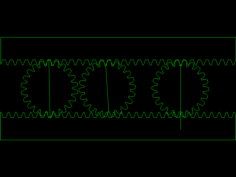
| 1074 forum posts 290 photos | Humble pie tastes horrible - arghh. I decided to try it out with a CAD program. The following *LINK* illustrates that randomly spaced pinions cannot be fitted between two racks. Gary |
| Billy Mills | 04/05/2014 14:31:07 |
| 377 forum posts | P)erhaps this might put it in words... The first pinion locks the tooth relationship between the gears or racks. Any extra pinions have to have the same amount of rotation as the first pinion. If a pinion is at a different rotation -say 1/4 tooth clockwise then the gear or rack needs to be 1/4 tooth around to fit one side of the pinion but the other side is then also 1/4 tooth clockwise whereas the pinion has been rotated so is 1/4 tooth anticlockwise i.e. the pinion cannot mesh both sides when at a diffferent relative position to the first pinion. Billy.
|
| John Stevenson | 04/05/2014 15:32:29 |
5068 forum posts 3 photos | Gary, you need Gravy with that pie, goes down easier.
There is actually nothing wrong with your theory only your drawing skills
Now if you had your two racks vertically in line and the gears on a vertical plane iy would work out correct.
However using a rack which is a gear with an infinite number of teeth isn't the answer because it can't be divided by 3
Now if we use say two 30 T racks bent round we get a 30 T gear and if each of the three pinions is dropped on every 10 teeth then it all works out correct and the spacing is 120 degrees.
Now if we had 31 teeth then the whole lot goes to pot because we can't have the factor "Equally spaced"
Now if we had a spider spaced at 116.129 degrees, 116.129 degrees and 127.741 degrees this would add up to 360 degrees and space the pinions out at 10 teeth, 10 teeth and 11 teeth. This answers the second part of the statement but cancels the first "equally Spaced part"
So it's easier to do the equally spaced bit than unequally spaced.
Sorry for the mind numbing maths Typo changed to "can't be divided by 3" Edited By John Stevenson on 05/05/2014 00:45:38 |
| jason udall | 04/05/2014 19:23:41 |
| 2032 forum posts 41 photos | Can one of the cognisant. .tell me how a bevel gear works...I mean you have two dissimilar diameters and the same module or DP... And the same tooth count on each end... Thinking of the bevel gear as a stack of infinity thin spur gears ...doesn'thelp. ... |
| John Stevenson | 04/05/2014 19:49:11 |
5068 forum posts 3 photos | It's not the same module or DP.
It reduces from the OD to the ID. I think Andrew covered this quite well in his article. The bit that actually matters is than for any given diameter on the gear what ever DP it is matches it's mating gear.
In theory a bevel with say a pitch of 12 DP on it's outer edge will have a DP at it's centre of an infinite number where it disappears up it's own, well we wont get into that. This is why bevel gears usually have a 1:3 ratio over the part used for the teeth so they are working with min and max acceptable numbers. |
| jason udall | 04/05/2014 20:51:37 |
| 2032 forum posts 41 photos | Thanks |
| Andrew Johnston | 05/05/2014 20:50:15 |
 7061 forum posts 719 photos | My first reaction when I saw this thread was 'Oh fudge (or words to that effect) I have missed an error'. Being busy yesterday with glider paperwork and inspections for the issue of an ARC (equivalent of the MOT) I then thought I'd let everyone sort it out. Which I think has now been done very satisfactorily. I did do a thought experiment which convinced me that I was correct, although it could possibly have been worded more clearly. Regards, Andrew
|
Please login to post a reply.
Magazine Locator
Want the latest issue of Model Engineer or Model Engineers' Workshop? Use our magazine locator links to find your nearest stockist!
Sign up to our Newsletter
Sign up to our newsletter and get a free digital issue.
You can unsubscribe at anytime. View our privacy policy at www.mortons.co.uk/privacy
Latest Forum Posts
- *Oct 2023: FORUM MIGRATION TIMELINE*
05/10/2023 07:57:11 - Making ER11 collet chuck
05/10/2023 07:56:24 - What did you do today? 2023
05/10/2023 07:25:01 - Orrery
05/10/2023 06:00:41 - Wera hand-tools
05/10/2023 05:47:07 - New member
05/10/2023 04:40:11 - Problems with external pot on at1 vfd
05/10/2023 00:06:32 - Drain plug
04/10/2023 23:36:17 - digi phase converter for 10 machines.....
04/10/2023 23:13:48 - Winter Storage Of Locomotives
04/10/2023 21:02:11 - More Latest Posts...
- View All Topics
Support Our Partners


Shopping Partners
Subscription Offer

Latest "For Sale" Ads
- Reeves** - Rebuilt Royal Scot by Martin Evans
by John Broughton
£300.00 - BRITANNIA 5" GAUGE James Perrier
by Jon Seabright 1
£2,500.00 - Drill Grinder - for restoration
by Nigel Graham 2
£0.00 - WARCO WM18 MILLING MACHINE
by Alex Chudley
£1,200.00 - MYFORD SUPER 7 LATHE
by Alex Chudley
£2,000.00 - More "For Sale" Ads...
Latest "Wanted" Ads
- D1-3 backplate
by Michael Horley
Price Not Specified - fixed steady for a Colchester bantam mark1 800
by George Jervis
Price Not Specified - lbsc pansy
by JACK SIDEBOTHAM
Price Not Specified - Pratt Burnerd multifit chuck key.
by Tim Riome
Price Not Specified - BANDSAW BLADE WELDER
by HUGH
Price Not Specified - More "Wanted" Ads...
Get In Touch!
Do you want to contact the Model Engineer and Model Engineers' Workshop team?
You can contact us by phone, mail or email about the magazines including becoming a contributor, submitting reader's letters or making queries about articles. You can also get in touch about this website, advertising or other general issues.
Click THIS LINK for full contact details.
For subscription issues please see THIS LINK.
Digital Back Issues


Donate

 Register
 Log-in
Model Engineer Magazine
- Percival Marshall
- M.E. History
- LittleLEC
- M.E. Clock

ME Workshop
- An Adcock
- & Shipley
- Horizontal
- Mill

Subscribe Now
- Great savings
- Delivered to your door

Pre-order your copy!
- Delivered to your doorstep!
- Free UK delivery!
All Forum Topics > Model Engineers' Workshop. > Machining Bevel Gears