Forum sponsored by:

Work holding problem
| Wolfie | 24/07/2013 14:54:36 |
 502 forum posts | Hi all I'm back in the workshop at last and I have a problem already. I want to clean up the ends of a slab of aluminium, doing one end and then milling the other to a particular length. However its a bit too big to clamp down. Its 12" long so can't put in the vice and its too wide to clamp on the mill bed, it covers all the t slots. I can clamp one end but not the other. Grrrr Ideas??
|
| David Littlewood | 24/07/2013 15:01:59 |
| 533 forum posts | Wolfie, Why is it too long to fit in the vice? If it is a chunky slab it should be rigid enough with say 4" overhang at each end. If not, hold it so one end is close the vice, clean up, move it so the other end is close to the vice, clock the clean end with a centre finder, wind along (ensuring you correct for backlash) and Robert, as they say, is your mother's brother. If for some reason this won't work, you may be able to clamp it to the bed using toolmakers' clamps, but this may restrict table movement. Alternatively, if it is to have any holes in it, make the holes first, use them to hold it to the table, and clean up ends to match hole location. David |
| Russell Eberhardt | 24/07/2013 16:07:18 |
 2785 forum posts 87 photos | I don't know what lathe you have but you may be able to clamp it to the cross-slide and use a flycutter in the chuck. Russell. |
| Andrew Johnston | 24/07/2013 16:46:52 |
 7061 forum posts 719 photos | Turn it through 90°, so it hangs off the front of the mill, setting perpendicular with a square on the edge of the table. Mill one end, and then turn it round. Andrew |
| Wolfie | 24/07/2013 22:13:31 |
502 forum posts | By in the vice I meant upright, in other words the vice has only the bottom end. I tried it the other way on and no matter which slot I mount the vice in the milling cutter doesn't quite traverse the whole end grrr. Tried mounting it lengthways but as I have to raise it off the bed getting it square is the problem there.
|
| Les Jones 1 | 24/07/2013 22:53:15 |
| 2292 forum posts 159 photos |
Hi Wolfie, Les. |
| JasonB | 25/07/2013 07:09:01 |
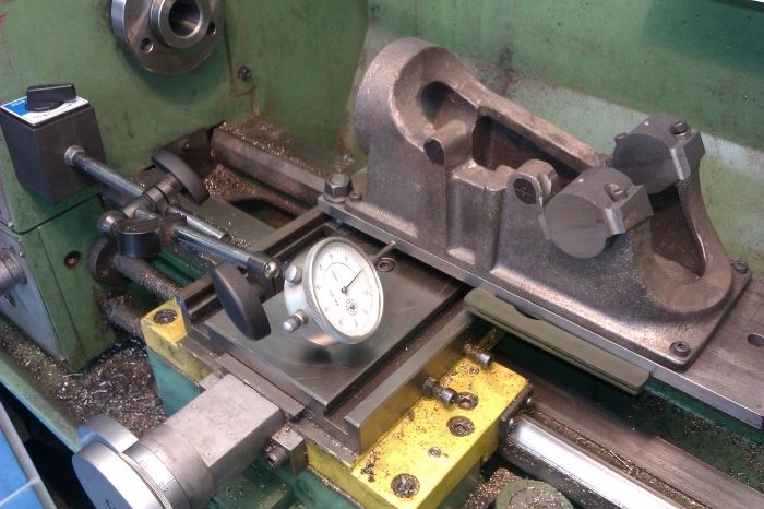
 25215 forum posts 3105 photos 1 articles | Wolfie can you give us the other two dimensions of teh block so we have a better idea of what needs machining. As les and Andrew say hanging it off the front of the mill is probably the best way as you have the longer X axis travel and just clock it in with a dial gauge. Or if you can't hold the squate against it when packed up put the stock of the square against the flat column but clocking it is more accurate. If you have enough movement on the cross slide of your lathe then pack it up off that and again clock it true before flycutting the end. I had to resort to this the other day on a large engine base casting
|
| Hopper | 25/07/2013 08:36:43 |
 7881 forum posts 397 photos | Couple of angle plates bolted to the t-slots and the block of aluminium clamped/bolted to the angle plates? |
| colin hawes | 25/07/2013 11:22:10 |
| 570 forum posts 18 photos | Sometimes on a job like this it is possible to drill and counterbore a couple of tooling holes in a place that won't show on the finished job or where they will subsequently be machined away. Then you can clamp into tee nuts. Colin |
Please login to post a reply.
Magazine Locator
Want the latest issue of Model Engineer or Model Engineers' Workshop? Use our magazine locator links to find your nearest stockist!
Sign up to our Newsletter
Sign up to our newsletter and get a free digital issue.
You can unsubscribe at anytime. View our privacy policy at www.mortons.co.uk/privacy
Latest Forum Posts
- *Oct 2023: FORUM MIGRATION TIMELINE*
05/10/2023 07:57:11 - Making ER11 collet chuck
05/10/2023 07:56:24 - What did you do today? 2023
05/10/2023 07:25:01 - Orrery
05/10/2023 06:00:41 - Wera hand-tools
05/10/2023 05:47:07 - New member
05/10/2023 04:40:11 - Problems with external pot on at1 vfd
05/10/2023 00:06:32 - Drain plug
04/10/2023 23:36:17 - digi phase converter for 10 machines.....
04/10/2023 23:13:48 - Winter Storage Of Locomotives
04/10/2023 21:02:11 - More Latest Posts...
- View All Topics
Support Our Partners


Shopping Partners
Subscription Offer

Latest "For Sale" Ads
- Reeves** - Rebuilt Royal Scot by Martin Evans
by John Broughton
£300.00 - BRITANNIA 5" GAUGE James Perrier
by Jon Seabright 1
£2,500.00 - Drill Grinder - for restoration
by Nigel Graham 2
£0.00 - WARCO WM18 MILLING MACHINE
by Alex Chudley
£1,200.00 - MYFORD SUPER 7 LATHE
by Alex Chudley
£2,000.00 - More "For Sale" Ads...
Latest "Wanted" Ads
- D1-3 backplate
by Michael Horley
Price Not Specified - fixed steady for a Colchester bantam mark1 800
by George Jervis
Price Not Specified - lbsc pansy
by JACK SIDEBOTHAM
Price Not Specified - Pratt Burnerd multifit chuck key.
by Tim Riome
Price Not Specified - BANDSAW BLADE WELDER
by HUGH
Price Not Specified - More "Wanted" Ads...
Get In Touch!
Do you want to contact the Model Engineer and Model Engineers' Workshop team?
You can contact us by phone, mail or email about the magazines including becoming a contributor, submitting reader's letters or making queries about articles. You can also get in touch about this website, advertising or other general issues.
Click THIS LINK for full contact details.
For subscription issues please see THIS LINK.
Digital Back Issues


Donate

 Register
 Log-in
Model Engineer Magazine
- Percival Marshall
- M.E. History
- LittleLEC
- M.E. Clock

ME Workshop
- An Adcock
- & Shipley
- Horizontal
- Mill

Subscribe Now
- Great savings
- Delivered to your door

Pre-order your copy!
- Delivered to your doorstep!
- Free UK delivery!
All Forum Topics > Beginners questions > Work holding problem