Forum sponsored by:

Encoder - How to build one?
Gear hobbing in the mill
| GoCreate | 02/11/2012 05:29:32 |
 387 forum posts 119 photos | Hi everyone, I am very interested in building an electronic gear box as referred to in MEW issue 108 and noted in this post. An encoder is needed but these look quite expensive to purchase, so I would also be interested in building one of these as well. There is some good info and photo in this thread. The electronic gear box circuit in issue 108 requires a phase A and phase B input from the encoder at 2000 pulses per rev of the gear hob. My question is how do I set up to get these phase A and phase B inputs? I have seen "quadrature" mentioned, but how does this work? I think the following will be the case but I am not 100% sure. 1. If I can make a 50 slot encoder disc (to keep the diameter a reasonable size). 2. Then have 2 photo electric switches to give phase A and phase B inputs. 3. Then arrange these switches so that one is set to switch at the leading edge of a slot (Phase A) and, at exactly the same time, the other set to switch at the trailing edge of a slot. (phase B) (I am very unclear on this point an how this gives the "quadrature". 4. So with 50 slots and quadrature I get 200 impulses per rev of the gear hob? 5. So to get 2000 impulses I need to gear up the encoder disc by 10 x the gear hob speed? My knowledge of electronics is extremely limited, any pointers in the right direction will be very much appreciated.
Nigel Edited By tractionengine42 on 02/11/2012 05:30:44 |
| Michael Gilligan | 02/11/2012 07:06:07 |
 23121 forum posts 1360 photos | Nigel, There is a lot of information out there on t'internet; but this is quite a good place to start. ... The humble computer mouse is an excellent donor. MichaelG. . Another useful reference Edited By Michael Gilligan on 02/11/2012 07:09:28 |
| GoCreate | 02/11/2012 14:26:48 |
387 forum posts 119 photos | Thanks Michael and Michael, very helpful info. I now understand the quadrature issue much better and how to place the photo switches.
I am busy sourcing the parts, some of the Farnell part no.s don't exist any more so I am having to source alternatives, great fun I am thinking of making the encoder disc with 3mm slots and using the photo switches specified by John S in the thread previously referenced. With 3mm between slots the disc come out at 107mm. I think this is manageable, 2mm slots would be better, I presume it depends upon the switches. I would rather play it safe and not get to fiddley.
Cheers Nigel |
| jason udall | 02/11/2012 14:57:56 |
| 2032 forum posts 41 photos | I have in the past used saw cuts.. Also holes work well and are easy. and this would allow for second track and " gear ratio" any appature bigger than say 0.1 mm will be fine
I would recomend photo interuptors with scmitt detector outputs.. (..) all the lowlevel signals are internal to the device and noise just goes away BUT IF DOING SO OBSERVE POLARITY they don't like it up 'em A zero index hole might prove helpful in the future so put one in now... All the best
|
| Stub Mandrel | 04/11/2012 21:17:59 |
 4318 forum posts 291 photos 1 articles | Hi Nigel, Not sure if you have realised or not but ideally the encoder signals should be symmetrical. You may need to reduce the width of the slots to compensate. See if you can find an old computer mouse - the kind with a wheel. These will have four pairs of opto source and detector inside along with two slotted wheels. Use two of ector pairs and copy the radial spacing and width (i.e. the angles not the actual width measurements) of the slots and you are sorted. Neil |
| GoCreate | 05/11/2012 04:11:30 |
387 forum posts 119 photos | Hi Jason, thanks for your post, very helpful information. Neil, I am asking around for an old mouse so I can have a look. I am finding this very interesting but still a little confusing. This is my latest encoder disc now at 63.5mm dia. with 100 - 0.5mm slots. Material between slots is nominally 1.5mm wide. So to get 2000 pulses I would have to gear it up 5:1. Am I correct in thinking that so long as I place one photo switch in the centre of a slot and the other in the centre of the material between the slot I will be OK?
I thought this photo switch might be OK.
. Cheers Nigel Edited By tractionengine42 on 05/11/2012 04:12:26 |
| jason udall | 05/11/2012 15:06:42 |
| 2032 forum posts 41 photos | the 2400 ( and more ) pulse/rev. encoders use one ( or more ) of two ways .. either VERY fine (etched on glass) lines or an array of photo interuptors to give multiple pulses for each " slit" ( think vernier ) say 8 pairs in one slot spacing like A B A B A B A B A B A B A B A B.. the A outputs are combined as are the B outputs giving 8 times the resolution... this combined with etched scales leads to encoders capabile of 25 000 pulses per rev. ( eg :OHE 25 K ET which is only 3" out side the case ) other encoders use phase and quad outputs of two analogue sine waves.. any way this doesn't move you any futher forward.. 50 slots is 7.2 degrees can you alighn the A B opto accurately enough to interpolate to the half slot? At say 3.6 not 3.9 degrees ?.. gears have back lash .. but an encoder on the input of a worm ( a la rotary table ) attains resolution and some how accuracy ( not thoughly convinced there) of the "gear" ratio
|
| wotsit | 05/11/2012 17:27:24 |
| 188 forum posts 1 photos | Neil (Stub) - I think the requirement for symmetric waveforms will depend on the subsequent electronics - IMO most 'dumb' electronic systems (TTL, CMOS, etc) would probably clock on the edges of the pulses, implying that so long as the waveforms were present with reasonably fast edges, then the symmetry is not so important for a simple system using only leading edge detection. However, one way to increase the number of pulses per rev is to use both the rising and falling edges of the waveform, and in that case, the quadrature waveforms need to be symmetrical, otherwise the pulses will tend to occur in pairs (two pulses, followed b a longer gap, then two more pulses - hope that makes sense). It is easy electronically to detect the rising and falling edges and combine them to provide quadrature pulse trains, providing two pulses for each slot in the wheel. This method was used in the original German design for an Electronic Lead Screw (sorry - forget the guys name just now) - there was some discussion about this in this forum. (Tony Jaffee is the expert on this, I think). An alternative to using a mechanical gearing system to increase resolution would be to use electronic phase-locked loop pulse multiplying system - I assume you want to measure rotational speed rather than absolute shaft position - this (put simply), is just an oscillator which produces the required output pulse. This output is divided by whatever multiplication is desired (e.g. 5), so a train of pulses at 1/5 the output frequency is produced. These pulses are compared with pulses produced from the optical wheel system, and an error signal is generated by the difference between the two pulse rates. This error signal is used to make the oscillator 'track' the mechanically produced pulses, but at (in this example) 5 times the frequency. There are easily available devices to perform this function (E.g CMOS 4046 and variants), or nowadays, PIC microcontrollers and the like can be programmed to do it. Another possible method is to measure the time between pulses, rather than the number of pulses per revolution. For example, if you have the simplest system with 1 pulse per revolution, then one (shaft) pulse can be used to trigger a counter driven by a high speed pulse generator. The following pulse from the shaft pulse generator indicates the end of the count. The number of pulse generator pulses counted between shaft pulses is a direct indication of shaft rotational speed, and can be many thousands if required. Note that any system using this will have some lag in response times (depends largely on how it is designed), because (in my example) at least one revolution must take place before a count is available. I don't think this is an issue for the requirement of hobbing, if you just want to maintain a definite ratio between the rotation of two components. Hope some of this is useful.
|
| John Stevenson | 05/11/2012 20:31:34 |
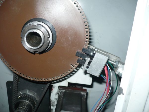
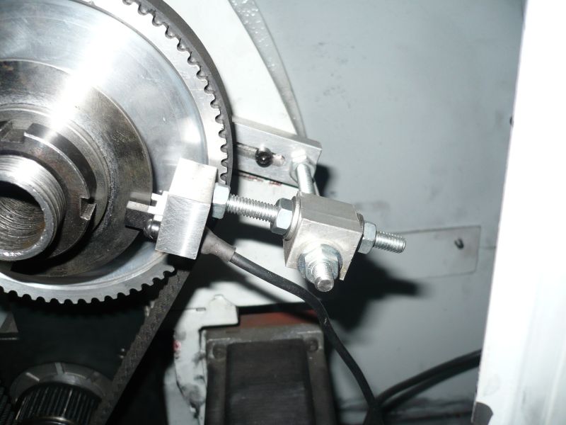
 5068 forum posts 3 photos | You need one to read the beginning of a slot and one to read the end of a slot, doesn't have to be the same slot.
Third one gives index.
This is a shot of the same machine with single slot encoder but it shows better how the whole lot can be adjusted to get all the correct angles and clearances.
John S. |
| Stub Mandrel | 05/11/2012 21:08:36 |
4318 forum posts 291 photos 1 articles | Hi Wotsit,
I asumed this was for a direct dividing head -hence my comments on symmetry which you seem to agree with For those who have micro controller experience if you use a pin change interrupt for each detector you can follow the vagaries of the movement at high speed. Neil
|


Please login to post a reply.
Magazine Locator
Want the latest issue of Model Engineer or Model Engineers' Workshop? Use our magazine locator links to find your nearest stockist!
Sign up to our Newsletter
Sign up to our newsletter and get a free digital issue.
You can unsubscribe at anytime. View our privacy policy at www.mortons.co.uk/privacy
Latest Forum Posts
- hemingway ball turner
04/07/2025 14:40:26 - *Oct 2023: FORUM MIGRATION TIMELINE*
05/10/2023 07:57:11 - Making ER11 collet chuck
05/10/2023 07:56:24 - What did you do today? 2023
05/10/2023 07:25:01 - Orrery
05/10/2023 06:00:41 - Wera hand-tools
05/10/2023 05:47:07 - New member
05/10/2023 04:40:11 - Problems with external pot on at1 vfd
05/10/2023 00:06:32 - Drain plug
04/10/2023 23:36:17 - digi phase converter for 10 machines.....
04/10/2023 23:13:48 - More Latest Posts...
- View All Topics
Support Our Partners


Shopping Partners
Subscription Offer

Latest "For Sale" Ads
- Reeves** - Rebuilt Royal Scot by Martin Evans
by John Broughton
£300.00 - BRITANNIA 5" GAUGE James Perrier
by Jon Seabright 1
£2,500.00 - Drill Grinder - for restoration
by Nigel Graham 2
£0.00 - WARCO WM18 MILLING MACHINE
by Alex Chudley
£1,200.00 - MYFORD SUPER 7 LATHE
by Alex Chudley
£2,000.00 - More "For Sale" Ads...
Latest "Wanted" Ads
- D1-3 backplate
by Michael Horley
Price Not Specified - fixed steady for a Colchester bantam mark1 800
by George Jervis
Price Not Specified - lbsc pansy
by JACK SIDEBOTHAM
Price Not Specified - Pratt Burnerd multifit chuck key.
by Tim Riome
Price Not Specified - BANDSAW BLADE WELDER
by HUGH
Price Not Specified - More "Wanted" Ads...
Get In Touch!
Do you want to contact the Model Engineer and Model Engineers' Workshop team?
You can contact us by phone, mail or email about the magazines including becoming a contributor, submitting reader's letters or making queries about articles. You can also get in touch about this website, advertising or other general issues.
Click THIS LINK for full contact details.
For subscription issues please see THIS LINK.
Digital Back Issues


Donate

 Register
 Log-in
Model Engineer Magazine
- Percival Marshall
- M.E. History
- LittleLEC
- M.E. Clock

ME Workshop
- An Adcock
- & Shipley
- Horizontal
- Mill

Subscribe Now
- Great savings
- Delivered to your door

Pre-order your copy!
- Delivered to your doorstep!
- Free UK delivery!
All Forum Topics > CNC machines, Home builds, Conversions, ELS, automation, software, etc tools > Encoder - How to build one?