Forum sponsored by:

Firefly .46 crankcase
| JasonB | 11/06/2012 18:45:02 |
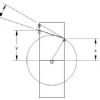
 25215 forum posts 3105 photos 1 articles | The series kicks off in 4432 with a description of machining the crankcase, the text states several times that the large hole in the rear of the block is 30mm dia. The rear view of the crancase on drawing WF46-0003 clearly shows this hole as 28.2mm dia. The plan view shows the cylinder mounting bolt holes spaced wider than this bore and dimensioned at 30mm cts which seems to tie up with the hole being 28.2mm Can someone confirm if the text is wrong or the drawing, not a good start. J Edited By JasonB on 11/06/2012 18:52:46 |
| JasonB | 11/06/2012 20:17:47 |
25215 forum posts 3105 photos 1 articles | Having now looked at a drawing of the backplate that fits into this hole, the text is obviously wrong. Can David, Diane, Alex or Frank comment on this, was Frank building to an earlier revision of the drawings or did he mistake the 30mm bolt cts as the bore?
J |
| Oil Magnet | 11/06/2012 21:37:38 |
 16 forum posts 6 photos | Hi J, If you have'nt already, you could take a look at Alexe's web site, there's a section on the firefly there.
regards om. |
| JasonB | 11/06/2012 21:52:12 |
25215 forum posts 3105 photos 1 articles | Thanks OM, that is we're I looked at the backplate drawing to confirm its size which confirms the drawing is correct and text wrong as the plate is machines 28.15 for an airtight fit which it won't be in a 30mm hole. J |
| David Clark 1 | 11/06/2012 23:46:32 |
 3357 forum posts 112 photos 10 articles |
Hi There
|
| JasonB | 12/06/2012 07:34:45 |
25215 forum posts 3105 photos 1 articles | Well I had already reached that conclusion but still does not explain why the author is talking about boring a 30mm hole, and the length of another hole to meet this one. You gave the same answer on the Northumbrian frames and we know where that ended up!! I'll repeat my question "Can David, Diane, Alex or Frank comment on this, was Frank building to an earlier revision of the drawings or did he mistake the 30mm bolt cts as the bore?" I also see that on Mr whittakers site there is a big note saying "updated plans comming soon" As MHS have stupidly chosen to remove the revision letter from the drawings what actual revision are you publishing is it an old one, the current one or these future updatted ones?
J Edited By JasonB on 12/06/2012 07:36:02 |
| David Clark 1 | 12/06/2012 08:53:18 |
3357 forum posts 112 photos 10 articles | Hi There
We are publishing drawings as supplied with no redrawing. regards David |
| JasonB | 12/06/2012 10:14:01 |
25215 forum posts 3105 photos 1 articles | Well whoever added the MHS logo put it in place of the revision details ans I doubt Alex W did that. Its also likely that the same poerson removed the revision letter from the bottom left corner. Take a look at this drawing it clearly shows revision number, revisions list and the hole as 28.2mm |
| David Clark 1 | 12/06/2012 10:16:30 |
3357 forum posts 112 photos 10 articles | Hi There I think I know what has happened. The drawings were originally supplied to RCM&E. Perhaps they modified them? I have not had them altered at all. regards david |
| KWIL | 12/06/2012 10:56:25 |
| 3681 forum posts 70 photos | David, Not to split hairs but RCM&E is still MHS, I would have thought parts of the same organistion could speak to each other, or is this just another of your burdens we must live with? |
| David Clark 1 | 12/06/2012 11:07:43 |
3357 forum posts 112 photos 10 articles | Hi Kwil Why would they tell me they deleted the issue number? The drawings were supplied by Alex Whittaker. I assumed he had some sort of agreement with MyHobbyStore to display the logo on his drawings. regards David
|
| john kennedy 1 | 12/06/2012 12:09:42 |
 214 forum posts 24 photos | Well spotted Jason. This also affects the wall thickness dimension given in the text as 3.75mm. Should be 4.65mm. Drawings seem ok though. Will give this engine a try. |
| JasonB | 12/06/2012 12:46:12 |
25215 forum posts 3105 photos 1 articles | Yes the wall thickness in teh text suits the larger size hole so there is a risk of someone machining the bore to drawing and then the wall thickness to the text and ending up with a small block. And while I'm on there are not enough dimensions for the two side chamfers, we only have the 6.75mm short side, the drawing either needs the angle as per the other chamfers or the long dimension as they stop just short of the chamfer on the top carb face. I know the chamfers are not critical but the info is not there and I'm surprized that of the six or so builders none noticed this? I quite fancy giving it a go myself but would like to know why the author says 30mm before cutting metal and I'll likely wait for a few more installments to be published. David in his intro Alex says that that the proving group builders will "make their expertise available via e-mail" now I can understand them not wanting all and sundry bombarding them with e-mails but I assume you have Frank's e-mail would it be possible to ask him to explain where the 30mm comes from ?
Edited By JasonB on 12/06/2012 13:17:26 |
| Terryd | 12/06/2012 16:05:26 |
 1946 forum posts 179 photos | Hi Jason, I haven't had my copy yet (via WHS) but you are quite right about the 28.2mm rear hole. I have just grabbed a moment to look at the full set of drawings on Alex' site and they all show it as that dimension (Rev C). As to email, I suspect that Alex wouldn't like his address being published but you can access him via an email link from his site (link above). It would probably be a good idea to publish that information in the articles. The only reason that I can think of for such an error is that the hole centres for the cylinder mounting holes are given as 30mm on the plan view and the article is being written well after the original build leading to confusion? As for the angles of the nose, the top and bottom are given as angles while the sides are shown as beong derived from the dimensions (23.5 x 6.75mm) I have some offcuts of suitable alloy so may have a go at this engine if these niggles can be sorted. Regards Terry |
| JasonB | 12/06/2012 16:05:40 |
25215 forum posts 3105 photos 1 articles | Just for a bit of fun have a play with this, hold your mouse button down on the drawing and then move it about to see the engine from any angle. Also in views, click transparent. David, can a link to Alex's site be added to the next available ME as I'm sure it will help anyone building the engine.
J |
| KWIL | 12/06/2012 16:49:28 |
| 3681 forum posts 70 photos | Good game! |
| JasonB | 12/06/2012 17:15:54 |
25215 forum posts 3105 photos 1 articles | Its is indeed Ken. Terry where are you getting your 23.5 (or23.45) from? The top slope that the carb opening is in is 23.45 back from the front of the casting but the side slopes are not quite so long, I would guess at 22mm which would give 17deg near as dam it. Thats why I said we need the length or angle.
Jason
PS I've just bandsawn a lump of some 2"x4" flat stock that I had Edited By JasonB on 12/06/2012 17:22:57 |
| mgnbuk | 12/06/2012 19:21:52 |
| 1394 forum posts 103 photos | Jason, Not directly related to the engine, but a query about the link showing the 3D model as a .pdf We received a component drawing from a prospective customer today in this form & would like to get dimensions from it - do you know if this is possible ? Right clicking on the page gets a menu that includes "3D preferences" - in here are settings for 2D and 3D measurement, but there doesn't appear to be a toolbar for measuring ? Being able to check dimensions on the Cad model would maybe help with the point you initially raised ? Regards, Nigel B |
| Andrew Johnston | 12/06/2012 19:51:20 |
 7061 forum posts 719 photos | I've been using 3D PDFs to send parts to clients for some years; so far I've never found a way to make measurements. The PDF files are smaller than the native part files by about an order of magnitude. I assume the PDFs define the part in a way that does not allow measurement? Regards, Andrew |
| Terryd | 13/06/2012 05:19:05 |
1946 forum posts 179 photos | Hi Jason, I see your point on the 23.45mm (sorry about the typo) dimension on the drawing on Alex' site but the 3d pdf you linked to appears to show the side and top slopes to end at the same dimension if you view it from above.
I have little experience of building i.c. engines and am not sure of the significance or importance of such a discrepancy,unlike that of the conflicting dimensions of the rear hole. I would be grateful for any light you can throw on this. I have a lot of respect for your experience and have been grateful for your observations on the portable engine. Best regards Terry |


Please login to post a reply.
Magazine Locator
Want the latest issue of Model Engineer or Model Engineers' Workshop? Use our magazine locator links to find your nearest stockist!
Sign up to our Newsletter
Sign up to our newsletter and get a free digital issue.
You can unsubscribe at anytime. View our privacy policy at www.mortons.co.uk/privacy
Latest Forum Posts
- *Oct 2023: FORUM MIGRATION TIMELINE*
05/10/2023 07:57:11 - Making ER11 collet chuck
05/10/2023 07:56:24 - What did you do today? 2023
05/10/2023 07:25:01 - Orrery
05/10/2023 06:00:41 - Wera hand-tools
05/10/2023 05:47:07 - New member
05/10/2023 04:40:11 - Problems with external pot on at1 vfd
05/10/2023 00:06:32 - Drain plug
04/10/2023 23:36:17 - digi phase converter for 10 machines.....
04/10/2023 23:13:48 - Winter Storage Of Locomotives
04/10/2023 21:02:11 - More Latest Posts...
- View All Topics
Support Our Partners


Shopping Partners
Subscription Offer

Latest "For Sale" Ads
- Reeves** - Rebuilt Royal Scot by Martin Evans
by John Broughton
£300.00 - BRITANNIA 5" GAUGE James Perrier
by Jon Seabright 1
£2,500.00 - Drill Grinder - for restoration
by Nigel Graham 2
£0.00 - WARCO WM18 MILLING MACHINE
by Alex Chudley
£1,200.00 - MYFORD SUPER 7 LATHE
by Alex Chudley
£2,000.00 - More "For Sale" Ads...
Latest "Wanted" Ads
- D1-3 backplate
by Michael Horley
Price Not Specified - fixed steady for a Colchester bantam mark1 800
by George Jervis
Price Not Specified - lbsc pansy
by JACK SIDEBOTHAM
Price Not Specified - Pratt Burnerd multifit chuck key.
by Tim Riome
Price Not Specified - BANDSAW BLADE WELDER
by HUGH
Price Not Specified - More "Wanted" Ads...
Get In Touch!
Do you want to contact the Model Engineer and Model Engineers' Workshop team?
You can contact us by phone, mail or email about the magazines including becoming a contributor, submitting reader's letters or making queries about articles. You can also get in touch about this website, advertising or other general issues.
Click THIS LINK for full contact details.
For subscription issues please see THIS LINK.
Digital Back Issues


Donate

 Register
 Log-in
Model Engineer Magazine
- Percival Marshall
- M.E. History
- LittleLEC
- M.E. Clock

ME Workshop
- An Adcock
- & Shipley
- Horizontal
- Mill

Subscribe Now
- Great savings
- Delivered to your door

Pre-order your copy!
- Delivered to your doorstep!
- Free UK delivery!
All Forum Topics > Model Engineer. > Firefly .46 crankcase