Forum sponsored by:

Milling Course
| Wolfie | 02/01/2012 14:44:34 |
 502 forum posts | I'm not sure whether this should go in here or down in the toolmaking section. As you know, I have started by making my small steam engine with the eventual target being a beam engine. I guess the steam engine has proceeded so slowly because I keep having to stop and learn techniques and make tools and along the way I have discovered an enjoyment for toolmaking for its own sake.  I have finally ordered a milling machine, an Amadeal XJ300-12. Basically its as far as I can go financially and space wise at this time. I am going to work through Harolds Milling machine course book (WPS 35). I have it and I've studied it and I have the metal on order to make the clamps, t-nuts and studs etc. Then its on to the three projects at the end, boring head, dividing head and grinding rest. I can already see that theres some things I'm going to struggle with as I don't fully understand all the diagrams. What I mean is I am having trouble visualising the 3 dimensional object that they are trying to tell me about. For instance there are clearly holes to be drilled in one piece but they don't go all teh way through (I don't think) but nowhere can I find a depth dimension.  Anyway when it comes to it I'm going to hope some of you have done some of these projects so I can pick your brains. Edited By Wolfie on 02/01/2012 14:45:13 |
| wheeltapper | 02/01/2012 16:13:00 |
 424 forum posts 98 photos | Hi I've made the dividing head,  and the basic grinding rest, 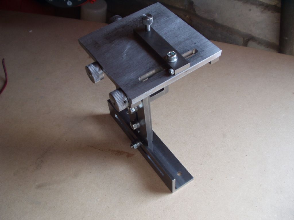 so if I can help, just yell. Roy |
| John Haine | 02/01/2012 18:31:34 |
| 5563 forum posts 322 photos | If the depth isn't shown, I guess it may be a blind threaded hole, just work out how deep it has to be to fit the mating screw or bolt. |
| Nicholas Farr | 02/01/2012 19:40:23 |
 3988 forum posts 1799 photos | Hi Wolfie, you don't say which piece you can't find the depth of the blind holes, but the ones that I have looked at with blind holes don't give a depth on the drawings, however, all these holes have a letter designation and the hole size and depth is given in the text that accompanies them, e.g. B M6 X 15 deep 2 off, C M5 X 12 deep 4off ect.
Hope this helps.
Regards Nick. |
| Wolfie | 14/01/2012 17:40:32 |
502 forum posts | Right then. I've done all the basic stuff and I now have a home made clamping set and I'm dead chuffed so no laughing  . I made a few mistakes, but I know what they are. . I made a few mistakes, but I know what they are. |
| wheeltapper | 14/01/2012 17:48:26 |
424 forum posts 98 photos | Nice. Coming along nicely. Roy |
| Springbok | 14/01/2012 17:48:42 |
 879 forum posts 34 photos | Well done Wolfie congrats
Bob |
| Alex gibson | 14/01/2012 19:49:25 |
| 35 forum posts | Hi Wolfie,
well done, I made the same set from the book a few months ago. I've since tapped some of the round holes in the clamp plates to m12. This mod allows you to use a m12 bolt as a jack screw. I've found this to be quite useful.
regards
alex
|
| Wolfie | 14/01/2012 21:18:37 |
502 forum posts | Whats a jack screw? |
| Harold Hall 1 | 14/01/2012 23:22:37 |
| 418 forum posts 4 photos | Have a look Wolfie at photo 6 on this page http://www.homews.co.uk/page292.html This shows on the right, a screw threaded into the clamp which avoids having a nut under the clamp. That is the head of a screw at the bottom not a nut with the stud passing through the lower plate, hope that's clear. I am sorry that I did not also add this method in my book but clamps with plain holes are also necessary for some methods. Typically, see photo 13 on page 57 in the book that you are working to. And, as I say above, a screw can be used with a nut on either side of the clamp, there are lots of examples of this in the book. Threaded with a screw into this in place of the nuts is though just a little easier to use . Consider making a few smaller clamps and with an M6 tapped hole for use where space is tight, see photo 4 on this page http://www.homews.co.uk/page372.html Hope this helps Harold I should have added Wolfie its good to see your efforts in the photograph above, they look better than mine! Edited By Harold Hall 1 on 14/01/2012 23:24:41 Edited By Harold Hall 1 on 14/01/2012 23:29:13 |
| Alex gibson | 14/01/2012 23:34:31 |
| 35 forum posts |
Hi Wolfie,
thanks to harold for that explanation, I was struggling to put it into words, the reason i went for the m12 thread was that you can still use the clamp plate as originally intended with a 10mm stud. I would post a pic to clarify if only I knew how.
regards
alex
Ps; thanks Harold, I'm just about to buy the material to start the project in chapter seven, l think this will be a useful addition to my shop (garage)
 kind regards
alex
Edited By Alex gibson on 14/01/2012 23:41:06 |
| Wolfie | 15/01/2012 00:16:44 |
502 forum posts | I'm just about to buy the material to start the project in chapter seven, l think this will be a useful addition to my shop (garage) Aye mines a garage too. Funnily enough so am I. I don't think I need a boring head at the moment but I do have a use for a dividing head. Although having said that its probable that the grinding head will be of more use to me at the current time. I'd have gone for that first, but the text says that you will learn stuff from one project to make the next so I'm worried that by going straight for grinding rest I'll miss summat. And thankyou Harold for your extra notes. Can you do me a favour and check your PMs  Edited By Wolfie on 15/01/2012 00:18:31 |
| Nicholas Farr | 15/01/2012 00:29:55 |
3988 forum posts 1799 photos | Hi Wolfie, your efforts are looking very good. So, you've made a few mistakes, but thats the way we learn, my mentors always told me, that he who never makes a mistake, never makes anything. I've been making things in engineering for more years than I have got left, and I still make a few mistakes, but with experience you can often work round many mistakes, and achieve the end result.
But sometimes you just have to bin 'em and start again.
Regards Nick. Edited By Nicholas Farr on 15/01/2012 00:33:38 |
| Alex gibson | 15/01/2012 00:56:57 |
| 35 forum posts | Hi again Wolfie,
I must confess I've skipped chapter six (sorry Harold) only because I was given a boring head.
soldier on Wolfie
regards
alex
|
| Andrew Johnston | 15/01/2012 11:09:18 |
 7061 forum posts 719 photos | Hi Wolfie, Looks pretty damn fine to me; very impressive. Next thing is to make some more; you can never have too many clamps and T-nuts! Remember, they're not mistakes, they're 'features'. Regards, Andrew |
| Harold Hall 1 | 15/01/2012 14:19:47 |
| 418 forum posts 4 photos | I agree Andrew! If you make any more T nuts make a couple with the tapped hole close to the side. You are likely to gain around 3-4mm, especially if you are using M8 studs. These, occasionally, will enable you to get a fixing in a place where as standard T-nut will not. Typically useful where the slots in an angle plate just do not line up with the slots in the machine table. Harold |
| Stub Mandrel | 15/01/2012 20:30:53 |
 4318 forum posts 291 photos 1 articles | Nice to see some pictures of your work Wolfie. Here's some 'interesting' clamping - a temporary jig for quartering loco wheels I set up today: 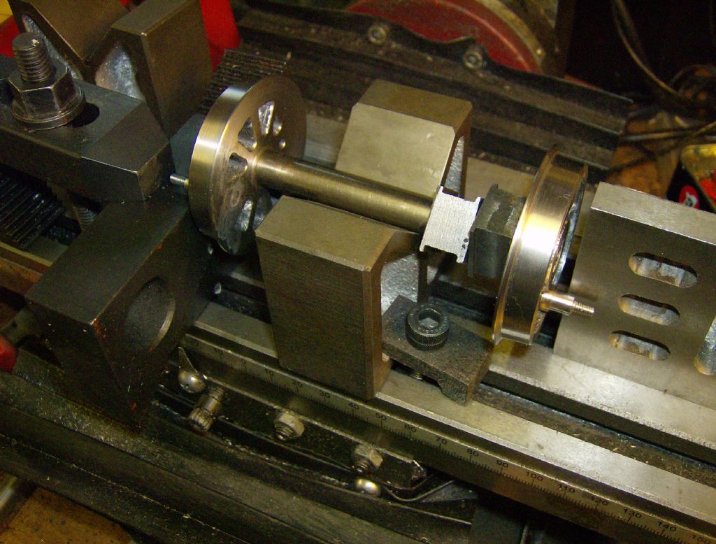 You can see the HUGE size of a 'standard' clamping set with M10 studs at left - the clamp and three packing blocks fill about a third of the mill table! The wee clamp holding teh V-block in place has a single M8 screw holding it (my home made clamps aren't quite as pretty as yours - this was just a slice of a suitably shaped bit of scrap malleable cast iron with a hole drilled in it) and the angle plate is held by a single M6 screw. Neil |
| Harold Hall 1 | 15/01/2012 22:56:58 |
| 418 forum posts 4 photos | You mention Wolfie that you are making the Grinding rest prior to the boring head and dividing head but are concerned about needing the earlier items to get the experiance. It is though more a case of needing the first item to make the second. However, whilst the dividing head is required to calibrate the dials on the grinding rest, this is far from essential and can be used easily without calibrated dials. Tool and cutter grinding is done at very small depths and the calibration just helps to set on such small amounts. They can of course be calibrated later or use the method I suggest for the boring head, see Sk2 on page 56 and the text on page 57. The boring head is though required to make the dividing head as there are some large holes to be bored that will probably be difficult to do on the lathe unless you have a larger one, somewhat larger than a Myford that is. Harold |
| Wolfie | 16/01/2012 00:06:49 |
502 forum posts | I use a Smart & Brown A Mk 2, reckon thats big enough. Not bad for a beginner eh!  Edited By Wolfie on 16/01/2012 00:08:19 |
| David Haynes | 16/01/2012 15:17:43 |
| 168 forum posts 26 photos | Wolfie, it's good to see your milling machine progress, going through Harold's Milling machine course book (WPS 35). Although I chose the later book in the series, the Milling Machine (WPS 49) fom last year, I was most disappointed to find that although all these accessories are discussed and photographed, there are no working drawings. It seems a shame that the latest book in the series misses these useful items out.
Also, does your lathe do screw cutting? I have had a lot of success making compression springs with my ML7. Okay, so it's only piano wire, but okay for most purposes. Dave |
Please login to post a reply.
Magazine Locator
Want the latest issue of Model Engineer or Model Engineers' Workshop? Use our magazine locator links to find your nearest stockist!
Sign up to our Newsletter
Sign up to our newsletter and get a free digital issue.
You can unsubscribe at anytime. View our privacy policy at www.mortons.co.uk/privacy
Latest Forum Posts
- *Oct 2023: FORUM MIGRATION TIMELINE*
05/10/2023 07:57:11 - Making ER11 collet chuck
05/10/2023 07:56:24 - What did you do today? 2023
05/10/2023 07:25:01 - Orrery
05/10/2023 06:00:41 - Wera hand-tools
05/10/2023 05:47:07 - New member
05/10/2023 04:40:11 - Problems with external pot on at1 vfd
05/10/2023 00:06:32 - Drain plug
04/10/2023 23:36:17 - digi phase converter for 10 machines.....
04/10/2023 23:13:48 - Winter Storage Of Locomotives
04/10/2023 21:02:11 - More Latest Posts...
- View All Topics
Support Our Partners


Shopping Partners
Subscription Offer

Latest "For Sale" Ads
- Reeves** - Rebuilt Royal Scot by Martin Evans
by John Broughton
£300.00 - BRITANNIA 5" GAUGE James Perrier
by Jon Seabright 1
£2,500.00 - Drill Grinder - for restoration
by Nigel Graham 2
£0.00 - WARCO WM18 MILLING MACHINE
by Alex Chudley
£1,200.00 - MYFORD SUPER 7 LATHE
by Alex Chudley
£2,000.00 - More "For Sale" Ads...
Latest "Wanted" Ads
- D1-3 backplate
by Michael Horley
Price Not Specified - fixed steady for a Colchester bantam mark1 800
by George Jervis
Price Not Specified - lbsc pansy
by JACK SIDEBOTHAM
Price Not Specified - Pratt Burnerd multifit chuck key.
by Tim Riome
Price Not Specified - BANDSAW BLADE WELDER
by HUGH
Price Not Specified - More "Wanted" Ads...
Get In Touch!
Do you want to contact the Model Engineer and Model Engineers' Workshop team?
You can contact us by phone, mail or email about the magazines including becoming a contributor, submitting reader's letters or making queries about articles. You can also get in touch about this website, advertising or other general issues.
Click THIS LINK for full contact details.
For subscription issues please see THIS LINK.
Digital Back Issues


Donate

 Register
 Log-in
Model Engineer Magazine
- Percival Marshall
- M.E. History
- LittleLEC
- M.E. Clock

ME Workshop
- An Adcock
- & Shipley
- Horizontal
- Mill

Subscribe Now
- Great savings
- Delivered to your door

Pre-order your copy!
- Delivered to your doorstep!
- Free UK delivery!
All Forum Topics > Beginners questions > Milling Course