Forum sponsored by:

Grayson Lathe
Motor Setup
| Mike Wainwright | 03/10/2011 19:50:23 |
| 149 forum posts 8 photos | Does anyone have a Grayson lathe simular to the one in my album. If you do, please could you show the setup of the pulleys and motor as I need to set my Grayson lathe now. Second point with this lathe. How do I know how much I am taking /cut as there was no measurement on the handles Pictures of my lathe are in my album Any help will be gratefully received or pictures of the setup would be great. Need to set the lathe up before a start on my Simplex loco |
| ady | 03/10/2011 21:47:53 |
| 612 forum posts 50 photos | Lathes.co.uk has a bit on them. There's some Grayson literature out there somewhere, I have a couple of pages of it but aint got a clue where it came from.   |
| Steve Garnett | 03/10/2011 23:26:48 |
| 837 forum posts 27 photos | Posted by Mike Wainwright on 03/10/2011 19:50:23: Second point with this lathe. How do I know how much I am taking /cut as there was no measurement on the handles Several possibilities here - temporarily fit a digital caliper to the slide, for instance, but that might be a bit of a pain... initially, I think that calibrating the dial is probably your best bet. You inspect the leadscrew carefully, and make sure it's the same as on the specification (8 tpi). This means that for every full turn of the cross-slide handle, you've moved the cutter 0.125". So, if you made up a temporary dial having 25 main divisions, that would give you 5 thou/division, and you could also divide each of these by 5 to give you 1 thou/smaller division. It shouldn't be too difficult to fit this - the handle looks as though it unscrews from the front, and making something to interpose temporarily there shouldn't be beyond the wit of anybody prepared to have a go at a loco, I would have thought. Same procedure applies to the compound slide handle - check the leadscrew pitch, and calibrate a dial for it. Edited By Steve Garnett on 03/10/2011 23:28:45 |
| Clive Foster | 03/10/2011 23:28:59 |
| 3630 forum posts 128 photos | Mike
Do you have a countershaft unit and simply need set up instructions or are you going to have to fabricate a unit?
If you need to make one I have a PDF "concept write-up" describing a couple of relatively easy to make set-ups based on ones I built for my two SouthBend 9" lathes. Both can be made without needing access to a working lathe but they are concepts only, not full designs, intended to be easily adaptable to use a variety of functionally equivalent components selected from whatever can be obtained cheaply or is in the handy box. If you fancy a copy contact me and I'll E-mail it.
Whatever countershaft you use a poly-vee "serpentine" belt of the type used on modern car engine accessory drives makes an excellent substitute for old style leather belts. Run it Vee side down, ant decent belt'n bearing supplier has a variety of widths and lengths not too expensive.
For measuring cut you could fit suitable size disks or dials to the cross and compound feed handles and stick a printed scale generated by your computer drawing program on. A band round the edge looks more proper but is harder to make as the length has to be right for the disk diameter. One stuck on the face is effective although you will need a pointer extended over the edge to show the reading. Laser print and varnish is pretty durable, 2 to 3 years at least unless thinners or something similarly aggressive gets on them, and replacements are easily made.
Clive |
| Mike Wainwright | 04/10/2011 07:48:27 |
| 149 forum posts 8 photos | Clive
Could you please email me your pdf when you get a chance.
|
| Flywheel | 04/10/2011 08:23:58 |
| 34 forum posts 1 photos | Hi Mike
I used to own a Grayson lathe like yours and I had the same trouble has you with no measurement on the handles, I cut a piece from a flexible metal tape measure 6 and 13/16" long which gave me 125 divisions and then turned a alluminium disc to fit on the cross slide screw behind the handle I then arranged a pointer to line up with the divisions [cant remember how I did this. [senior moments] but no doubt you can puzzle it out, I was working on a shoestring budget at the time and this was a cheap way round the problem, I think I also fitted the same idea to the leadscrew handle.
You could substitute the 6 and 13/16" for 125mm which would give you a smaller diameter disc to turn because it does not matter what system you use it is the number of divisions that is important
Regards Peter |
| Flywheel | 04/10/2011 08:27:31 |
| 34 forum posts 1 photos | Hi again Mike
I've just had another senior moment sorry
I forgot to say that I riveted {or glued} the piece of tape measure to the rim of the alloy disc
Peter |
| Flywheel | 04/10/2011 08:38:27 |
| 34 forum posts 1 photos | Hi Mike
Dont know if you know but the headstock spindle on the Grayson is the same thread as Myford and the Myford change gears can also be used [you have to drill a 1/16" hole in them for the Grayson pins clamp one of the original gears to the Myford gear and drill through ] also on the lathe that I had the crosslide threads were very worn so I bored out the crosslide thread and fitted a Myford crosslide screw and nut.
Peter |
| _Paul_ | 08/10/2011 19:45:44 |
 543 forum posts 31 photos | This is what mine looks like: 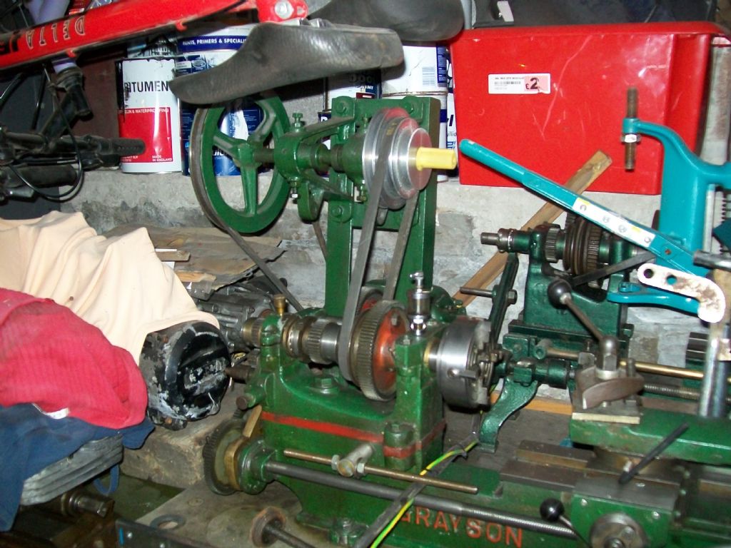 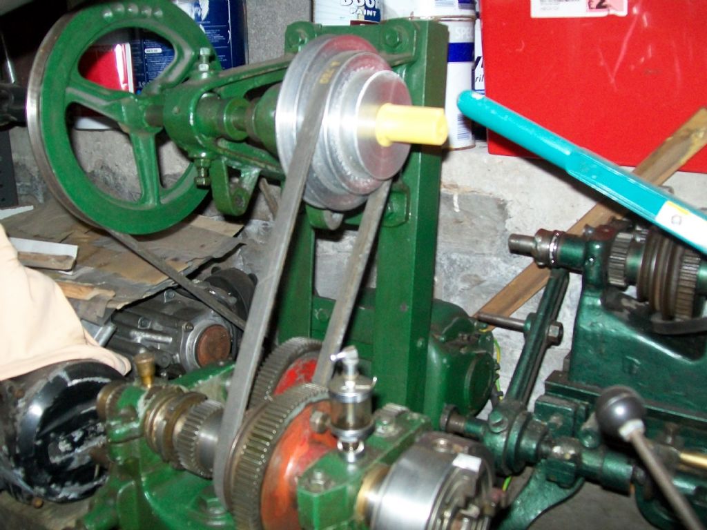 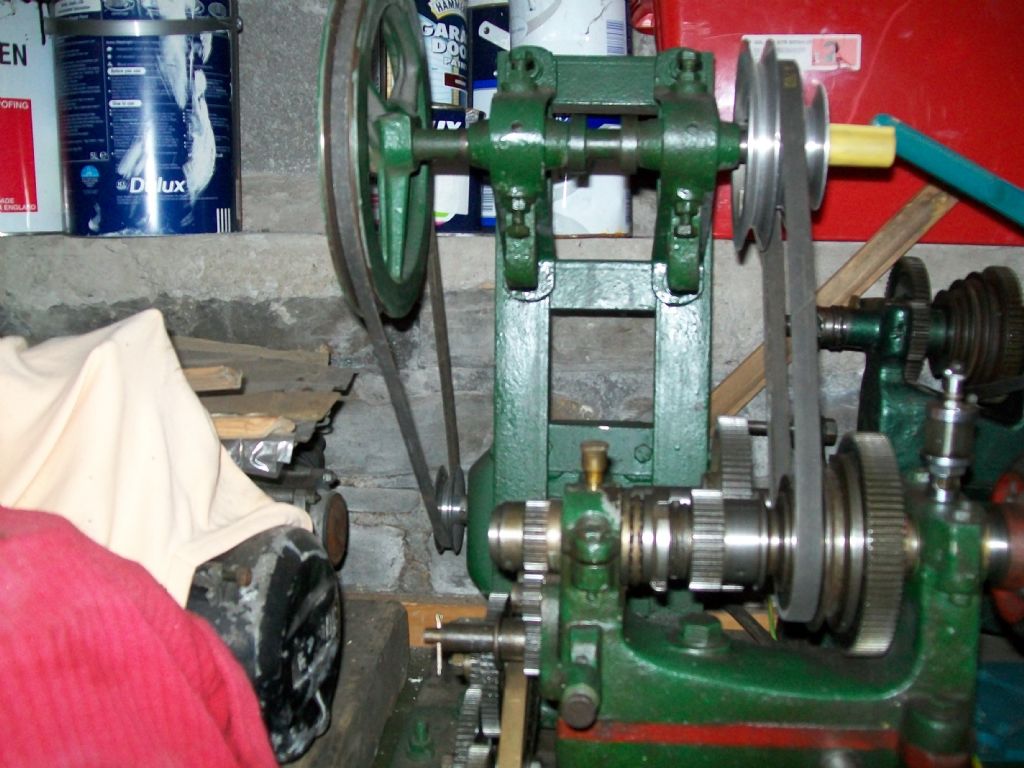 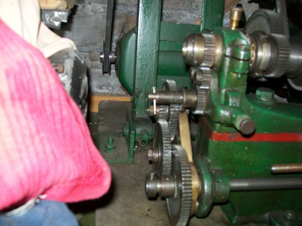 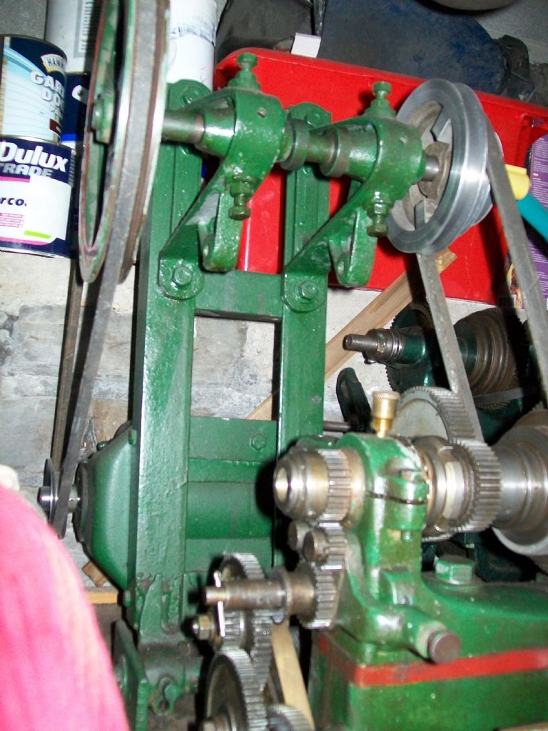 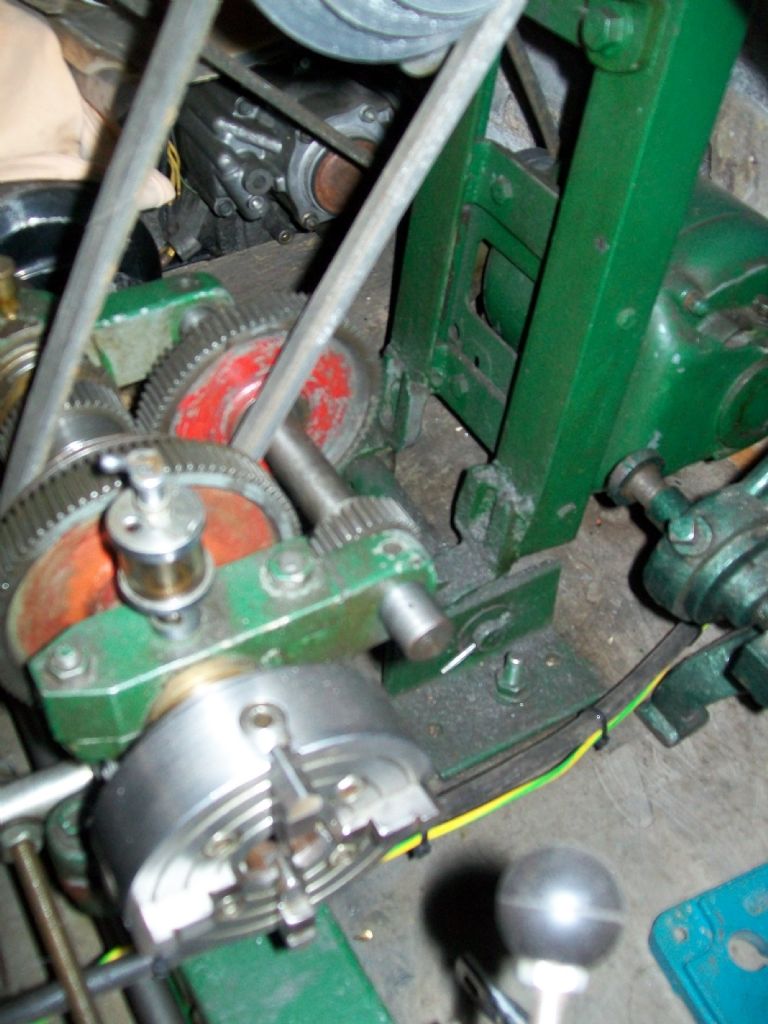 Regards Paul |
| Chris Trice | 09/10/2011 11:24:37 |
 1376 forum posts 10 photos | A quick "get you out of trouble" trick for unmarked handwheels is to simply scan a metal rule and resize the image in image manipulation software to suit the perimeter circumference of the handwheel before printing it and taping it on. You have the option to easily tweak the size to get it accurate. |
| ady | 09/10/2011 12:02:46 |
| 612 forum posts 50 photos | I would definitely recommend digitalising your cross slide. This completely eliminates backlash issues and allows you to change between metric and imperial at the push of a button. I got mine from this place because it has an auto switch off after around 2 mins of inactivity, the batteries are the cheapo AG13s from poundland, and it stores the measurement when it switches off, (some calipers reset at zero) http://www.ebay.co.uk/itm/290564367965  It's no' pretty, but it sure works great, wish I'd done it from the start. details of my own one in here |
| Mike Wainwright | 16/01/2012 08:08:10 |
| 149 forum posts 8 photos | I have decided to get the Grayson working instead of buying a new or secondhand lathe. It has been stripped down and everything cleaned up. The old motor has been stripped and cleaned. New NVR switch bought and the motor has been wired up. I have made a frame for the motor and countershaft. The garage opposite me welded it up for me. I bought 2 new plummer blocks and a few nuts and bolts. All I need to get everything working is a flat belt for the headstock drive.
I have contacted www.lathes.co.uk but they want £35.00 for a metre of belt. Does anyone know where I can get a length of belt so I can join it together. I do not want to have to strip the headstock down again to fit the belt.
As soon as I can get this then I can see if the lathe is working ok. I know the headstock bearing were replaced and there is no play on the movement of the slides.
|
| Flywheel | 16/01/2012 09:25:42 |
| 34 forum posts 1 photos | Can you let me know the width of the belt you require,[ if I remember correctly it is about 1" or 1 1/4" for the Grayson,] I might be able to help you |
| Keith Long | 16/01/2012 10:04:51 |
| 883 forum posts 11 photos | Hi Mike If you have a look on E-Bay, use the search phrase "flat drive belt" you'll find several suppliers who do it by the meter and can supply the alligator clips to join it. I bought mine from the chap in Penrhyndeudraeth, quick delivery and also wrote out the instructions for the clips. Very helpful. Keith |
| NJH | 16/01/2012 10:18:58 |
 2314 forum posts 139 photos | Mike I assume that this is a flat belt drive. If you are desperate you could find a gents leather trousers belt of suitable width, scarf the ends and overlap them. Then drill a pattern of small holes in a rectangular shape through both bits. Fit the belt around the headstock pulley, bond the overlapped ends together with something like Evostick then stitch through the holes you have drilled with some waxed twine. This is what I did with a Myford ML4 (a close relative of the Grayson) that I had some years ago and it worked well. I never needed to replace the belt and it had the bonus that , with my great inexperience, if I had a "dig in" the belt slipped and disaster was avoided! On the other hand if you have a "V" pulley try RDG. Regards Norman |
| Bazyle | 17/01/2012 11:17:47 |
 6956 forum posts 229 photos | Scales! next you'll be asking someone to invent a measuring system where everything is subdivided by factors of 10 so you can count on your fingers
 I recall a mention in an old ME, probably by Tubal Cain or the like about lathes without scales. The way to work is with a piece of chalk to mark the top of the flange then you can wind out X turns when needed and wind back in to exactly the same setting. Since people used to work to 64th and 128th not thou (which is why leadscrews are 8 tpi not 10) it is easy to estimate 1/8 th or 1/16 th of a turn from the chalk to put on a cut having measured the diameter of the work using calipers held up to a rule probably only showing 64ths.
Once you have carefully measured and cut a diameter at say 1/2 inch you only have to mark the setting and everything else smaller is relative to that as eg X turns plus 3/8 turn. Bit like using a dividing head.
|
| Stub Mandrel | 17/01/2012 21:26:58 |
 4318 forum posts 291 photos 1 articles | > Since people used to work to 64th and 128th not thou (which is why leadscrews are 8 tpi not 10) I made a 64-graduation index for my 16tpi leadscrew. Works well and iis close enough to a 'thou' over short distances. Neil |
Please login to post a reply.
Magazine Locator
Want the latest issue of Model Engineer or Model Engineers' Workshop? Use our magazine locator links to find your nearest stockist!
Sign up to our Newsletter
Sign up to our newsletter and get a free digital issue.
You can unsubscribe at anytime. View our privacy policy at www.mortons.co.uk/privacy
Latest Forum Posts
- *Oct 2023: FORUM MIGRATION TIMELINE*
05/10/2023 07:57:11 - Making ER11 collet chuck
05/10/2023 07:56:24 - What did you do today? 2023
05/10/2023 07:25:01 - Orrery
05/10/2023 06:00:41 - Wera hand-tools
05/10/2023 05:47:07 - New member
05/10/2023 04:40:11 - Problems with external pot on at1 vfd
05/10/2023 00:06:32 - Drain plug
04/10/2023 23:36:17 - digi phase converter for 10 machines.....
04/10/2023 23:13:48 - Winter Storage Of Locomotives
04/10/2023 21:02:11 - More Latest Posts...
- View All Topics
Support Our Partners


Shopping Partners
Subscription Offer

Latest "For Sale" Ads
- Reeves** - Rebuilt Royal Scot by Martin Evans
by John Broughton
£300.00 - BRITANNIA 5" GAUGE James Perrier
by Jon Seabright 1
£2,500.00 - Drill Grinder - for restoration
by Nigel Graham 2
£0.00 - WARCO WM18 MILLING MACHINE
by Alex Chudley
£1,200.00 - MYFORD SUPER 7 LATHE
by Alex Chudley
£2,000.00 - More "For Sale" Ads...
Latest "Wanted" Ads
- D1-3 backplate
by Michael Horley
Price Not Specified - fixed steady for a Colchester bantam mark1 800
by George Jervis
Price Not Specified - lbsc pansy
by JACK SIDEBOTHAM
Price Not Specified - Pratt Burnerd multifit chuck key.
by Tim Riome
Price Not Specified - BANDSAW BLADE WELDER
by HUGH
Price Not Specified - More "Wanted" Ads...
Get In Touch!
Do you want to contact the Model Engineer and Model Engineers' Workshop team?
You can contact us by phone, mail or email about the magazines including becoming a contributor, submitting reader's letters or making queries about articles. You can also get in touch about this website, advertising or other general issues.
Click THIS LINK for full contact details.
For subscription issues please see THIS LINK.
Digital Back Issues


Donate

 Register
 Log-in
Model Engineer Magazine
- Percival Marshall
- M.E. History
- LittleLEC
- M.E. Clock

ME Workshop
- An Adcock
- & Shipley
- Horizontal
- Mill

Subscribe Now
- Great savings
- Delivered to your door

Pre-order your copy!
- Delivered to your doorstep!
- Free UK delivery!
All Forum Topics > Beginners questions > Grayson Lathe