Forum sponsored by:

benchtop power supply
| ian weeks | 09/09/2011 23:31:52 |
| 33 forum posts | Dear All, whist building the gear banjo in MEW issue82 I once again read the article in the same issue by peter rawlinson on electronics in the workshop. It took me back to the 'radio and electronics club at school many decades ago. I resolved to build the project at the end of the article as a 'nostalgia trip'. However I have a problem -the circuit shows 4 of the capacitors as 10 microfarad 35vw but the pictures show one of these as a physically much bigger beast of an electrolytic[ viz the one across the output of the bridge rectifier]. My problem is that a little bell is ringing in my head and saying that this capacitor should br bigger but my knowledge is so rusty I cant be sure and I can see no corrections to the circuit inn subsequent issues. Any advice would be appreciated Regards Ian |
| Steve Garnett | 10/09/2011 02:09:41 |
| 837 forum posts 27 photos | I've looked at it - and I can see what you mean. As far as the value is concerned, yes it's a typo - if you read the first paragraph on page 49, the author mentions a capacitor of 4,700uF/35v and that's certainly more like what I'd expect to see as a reservoir capacitor in that position. Ideally you'd put in a high-ripple device too, but for a relatively small power supply that's not seriously important. Because all of these power supplies are regulated, they don't need larger capacitors between the regulation and whatever they're supplying, as the regulator does a rather better job on the output side than the capacitors would anyway. I think that every data sheet I've seen reflects this. In fact a good argument could be made that having a larger cap on the output makes it harder for the regulator to work properly. One other point about the general purpose power supply as shown is that I'd want a heatsink for each of the regulators, not just the LM338 - the 7805 needs one as well. That poor device is being supplied with over 30v at its input, which is fairly close to the maximum allowed, and the author says that you can have up to 1 amp from it. It's going to get pretty warm, and if its internal temperature reaches 150 degrees C, it will shut down. In this design, it could easily be dissipating 30W, so that's going to require a fair chunk of metal, and good thermal contact being made. The author shows it without one. Clearly he hasn't been using it! Edited By Steve Garnett on 10/09/2011 02:11:39 |
| ian weeks | 10/09/2011 10:01:44 |
| 33 forum posts | Dear Steve , Thanks very much for your advice and prompt reply.Its nice to get a bit of confirmation that not all the grey cells have gone. Also did wonder about the heat dissipation and bought heat sinks as you suggested. Thanks again Ian |
| Andrew Johnston | 10/09/2011 12:13:54 |
 7061 forum posts 719 photos | Posted by Steve Garnett on 10/09/2011 02:09:41: In fact a good argument could be made that having a larger cap on the output makes it harder for the regulator to work properly. Steve: I'm not sure I follow that; can you elucidate? Regards, Andrew |
| Steve Garnett | 10/09/2011 16:55:41 |
| 837 forum posts 27 photos | Elucidation (hopefully...) A larger capacitance at the output certainly decreases the magnitude of any transient response the regulator has to a change in load, but it also increases the device's settling time - and the larger you make it the worse this gets. All the time it's settling, it's not providing a steady-state regulated output! There's a T.I. App note about it - the relevant bit is at the end of the first page, and at the end of it there's the formula for calculating the optimum value for any given situation. Not that for most practical purposes it makes a significant difference - just sticking a 10uF low esr cap across the output is fine for the vast majority of applications. |
| Andrew Johnston | 10/09/2011 18:16:36 |
7061 forum posts 719 photos | Ah, my mistake! I read it as referring to the size of the reservoir capacitor on the input of the regulator; and I couldn't for the life of me see how that would affect the regulator. Oh well, where's the dunces cap? Regards, Andrew |
| Steve Garnett | 10/09/2011 18:48:31 |
| 837 forum posts 27 photos | You might be amazed how little you can get away with on the reservoir (input) side as well. Only trouble with doing this is that you're going to make the poor regulator work even harder. But hey, they claim that 7805s have an 85dB ripple rejection ratio... On a more important note, the other thing that is missing from the circuit as shown in issue 82 (with an isolator switch on the input) is any form of reverse-bias protection diode across the regulator. If you switch off the supply and for any reason you get some sort of output over-voltage situation, you stand a fair chance of wrecking the device. One chunky diode with the cathode connected to the input and the anode to the output will take care of that though. For more details see the 7805 data sheet. Ah, power supplies - don't ya just love them? Earlier this week I won an eBay auction for an Anilam Wizard 211 3-scale head which was being sold as 'not working'. It has a switch-mode power supply, about which there is no information, and it was very apparent that the major problem with it was that the bridge rectifier had got two shorted diodes in it. I now think that this takes the prize for being the one component that can cause the most collateral damage in a power supply! Three more diodes, the chopper FET, the current measuring resistor, the VDR on the input, both fuses, a couple of resistors that failed as a result of the current measuring resistor failing, probably the main smoothing cap (changed to be on the safe side), and the controlling IC. Changed the other two electrolytics in it as well, plus the start-up resistor. Took a whole two hours to fix all that satisfactorily. But at least it works again now - result! Edited By Steve Garnett on 10/09/2011 18:49:57 |
| Ian S C | 11/09/2011 12:50:28 |
 7468 forum posts 230 photos | 'Fraid i just use an un regulated supply. Originally it was the power supply for an old Zerox copier, the transformer is about 200 mm sq, as is its a single winding type(auto transformer?), there was plenty of room so I wound on another winding to give the 18 V that I wanted, its got a 45W bridge rectifier and 2500uf cap. Ian S C |
| Steve Garnett | 11/09/2011 14:40:13 |
| 837 forum posts 27 photos | It all depends what you want your power supply for, really. For many applications an unregulated supply is fine. Ian W. says he's building his as a nostalgia trip, but I bet he's got something else in mind really! I just build them as I need them, and usually they are original designs for specific purposes. For general experimenting though I have a couple of Farnell triple-output bench supplies, plus a few external current-limiting boxes which save the odd disaster. |
| Ian S C | 11/09/2011 15:36:58 |
7468 forum posts 230 photos | My supply gives me 18 V around my workshop, it powers the table feed on the mill, the electrolitic rust removal bath, a small automotive portable air compressor, and an 18V battery drill, and a hoist mounted above my lathe on a rail, I use that when changing chucks, they are 8' and just managable, so I'v got that for when I can't manage. Ian S C
|
| Ian S C | 11/09/2011 15:37:00 |
7468 forum posts 230 photos | My supply gives me 18 V around my workshop, it powers the table feed on the mill, the electrolitic rust removal bath, a small automotive portable air compressor, and an 18V battery drill, and a hoist mounted above my lathe on a rail, I use that when changing chucks, they are 8' and just managable, so I'v got that for when I can't manage. Ian S C
|
| Ian S C | 11/09/2011 15:37:01 |
7468 forum posts 230 photos | My supply gives me 18 V around my workshop, it powers the table feed on the mill, the electrolitic rust removal bath, a small automotive portable air compressor, and an 18V battery drill, and a hoist mounted above my lathe on a rail, I use that when changing chucks, they are 8' and just managable, so I'v got that for when I can't manage. Ian S C
ps. Motor on hoist ex garage door opener, rated 36V. Edited By Ian S C on 11/09/2011 15:39:18 |
| mick H | 11/09/2011 16:58:10 |
| 795 forum posts 34 photos | A few days ago I succumbed to a whim and bought a "12v DC 4 amp" power supply, thinking that it might power a 7.2v drill. It seems to produce "pulses" of power so that the drill continuously stutters on/off. I have little knowledge or understanding of these matters but cursory research indicates that it might be a switched mode device of some sort. I accept that it was probably a waste of money, but is there any use for it? |
| Les Jones 1 | 11/09/2011 17:10:14 |
| 2292 forum posts 159 photos | Hi Mick H, I suspect that the starting current of the drill exceeds 4 amps causing the power supply to start shutting down. There are probably many uses for it. For example electroplating, anodising, powering 12 volt bulbs etc. Les |
| Terryd | 11/09/2011 17:22:53 |
 1946 forum posts 179 photos | Posted by Ian S C on 11/09/2011 15:37:01: ................., they are 8' and just managable, so I'v got that for when I can't manage. Ian S C. Edited By Ian S C on 11/09/2011 15:39:18 Phew, I couldn't manage an 8' chuck even with a hoist. An 8" maybe, I'd love to see your lathe Ian, it must be a whopper  , ,Best regards Terry |
| Steve Garnett | 11/09/2011 21:04:26 |
| 837 forum posts 27 photos | Ha Ha. I think that this must be the one... 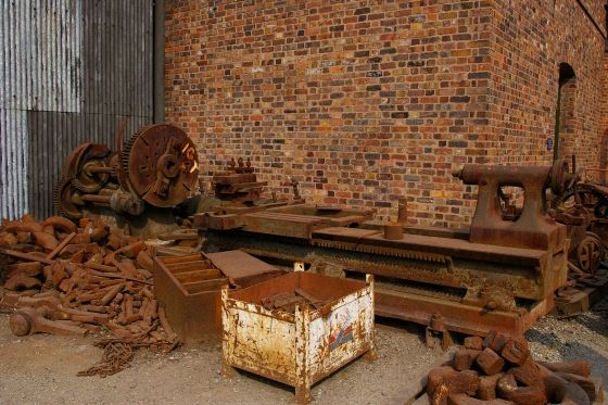 I think you could just get an 8' chuck on it! |
| Terryd | 11/09/2011 21:15:54 |
1946 forum posts 179 photos | Posted by Steve Garnett on 11/09/2011 21:04:26: Ha Ha. I think that this must be the one... Hi Steve, Super photo but not entirely convinced, I think that an 8' chuck would tax even that brute. Don'tcha just love those industrial archaeological pictures! Best regards Terry |
| ian weeks | 11/09/2011 21:57:26 |
| 33 forum posts | Thanks everyone for the information and entertainment .Steve is right I do have another little project in mind . Years ago a friend gave me an old bush battery valve radio which he was about to throw out . I just couldn't let that happen. It's been at the back of the workshop staring at me for some time Before I can even look at it I would need Batteries [not made anymore] or a power supply . When read the MEW article I thought If I can cobble The bench power supply together, Will have new supply for mill table feed /useful 5v if ever needed and its not a world away from HT/LT supply to play with old radio and stop it staring at me. Also I think I know that lathe in the photo -is it outside the foundry at the Ironbridge equivalent of Beamish by any chance?? Regards Ian |
| Les Jones 1 | 11/09/2011 23:08:43 |
| 2292 forum posts 159 photos | Hi Ian, Depending on the age of the old radio it will either need 2 volts for the heaters and 120 volts HT or 1.5 volts for the heaters and 90 volts HT. If the valves are B7G bases (7 pins with a a diameter of about 3/4" and about 2" high.) it will be the second type. The valve types will probable start with the letter D. Les. |
| Steve Garnett | 11/09/2011 23:27:46 |
| 837 forum posts 27 photos | Posted by ian weeks on 11/09/2011 21:57:26: Also I think I know that lathe in the photo -is it outside the foundry at the Ironbridge equivalent of Beamish by any chance?? Yes, it's at Blists Hill. I took the picture in a feeble attempt to wind my bro-in-law up. At the time I took the photo, he'd had a lathe outside under a tarpaulin for well over a couple of years without looking at it at all. This was just to suggest to him what sort of state it might be in! Turned out that his wasn't quite as rusty as that... And Terry, that's a gap-bed lathe. If you size it by looking at the imperial bricks in the wall behind it (about 3 rows/ft), the faceplate on it has to be best part of 6' diameter, so I reckon that an 8' chuck is just about within its capability. You probably wouldn't lose the chuck key in a hurry though... |
Please login to post a reply.
Magazine Locator
Want the latest issue of Model Engineer or Model Engineers' Workshop? Use our magazine locator links to find your nearest stockist!
Sign up to our Newsletter
Sign up to our newsletter and get a free digital issue.
You can unsubscribe at anytime. View our privacy policy at www.mortons.co.uk/privacy
Latest Forum Posts
- *Oct 2023: FORUM MIGRATION TIMELINE*
05/10/2023 07:57:11 - Making ER11 collet chuck
05/10/2023 07:56:24 - What did you do today? 2023
05/10/2023 07:25:01 - Orrery
05/10/2023 06:00:41 - Wera hand-tools
05/10/2023 05:47:07 - New member
05/10/2023 04:40:11 - Problems with external pot on at1 vfd
05/10/2023 00:06:32 - Drain plug
04/10/2023 23:36:17 - digi phase converter for 10 machines.....
04/10/2023 23:13:48 - Winter Storage Of Locomotives
04/10/2023 21:02:11 - More Latest Posts...
- View All Topics
Support Our Partners


Shopping Partners
Subscription Offer

Latest "For Sale" Ads
- Reeves** - Rebuilt Royal Scot by Martin Evans
by John Broughton
£300.00 - BRITANNIA 5" GAUGE James Perrier
by Jon Seabright 1
£2,500.00 - Drill Grinder - for restoration
by Nigel Graham 2
£0.00 - WARCO WM18 MILLING MACHINE
by Alex Chudley
£1,200.00 - MYFORD SUPER 7 LATHE
by Alex Chudley
£2,000.00 - More "For Sale" Ads...
Latest "Wanted" Ads
- D1-3 backplate
by Michael Horley
Price Not Specified - fixed steady for a Colchester bantam mark1 800
by George Jervis
Price Not Specified - lbsc pansy
by JACK SIDEBOTHAM
Price Not Specified - Pratt Burnerd multifit chuck key.
by Tim Riome
Price Not Specified - BANDSAW BLADE WELDER
by HUGH
Price Not Specified - More "Wanted" Ads...
Get In Touch!
Do you want to contact the Model Engineer and Model Engineers' Workshop team?
You can contact us by phone, mail or email about the magazines including becoming a contributor, submitting reader's letters or making queries about articles. You can also get in touch about this website, advertising or other general issues.
Click THIS LINK for full contact details.
For subscription issues please see THIS LINK.
Digital Back Issues


Donate

 Register
 Log-in
Model Engineer Magazine
- Percival Marshall
- M.E. History
- LittleLEC
- M.E. Clock

ME Workshop
- An Adcock
- & Shipley
- Horizontal
- Mill

Subscribe Now
- Great savings
- Delivered to your door

Pre-order your copy!
- Delivered to your doorstep!
- Free UK delivery!
All Forum Topics > Model Engineers' Workshop. > benchtop power supply