Forum sponsored by:

Machining cam lobes
| Styx | 30/06/2011 13:06:19 |
 34 forum posts 42 photos | I want to machine some cam lobes on the milling machine and I seem to remember a program that gave a list of co-ordinates in the z axis relative to a radial movement. This gave a stepped profile which needed a light dressing with a file. Can anyone shed any light on this or any other way of producing a cam lobe.
Thanks for any help.
Steve.... |
| David Clark 1 | 30/06/2011 13:13:22 |
 3357 forum posts 112 photos 10 articles | Hi There
Draw the cam shape out in a cad package.
Offset the outline by the radius of a ball nose cutter.
Plot the co-ordinates at say every .5mm or 20 thou vertically.
You can then machine the entire top half of the cam then rotate the job 180 degrees and machine all of the bottom.
Sketch to follow after lunch.
regards David
|
| JasonB | 30/06/2011 16:08:28 |
 25215 forum posts 3105 photos 1 articles | Thats a long lunch David
There are a couple of calculators on Model engine news site, just turn the blank in a rotary table, adjust z feed mill and repeat.
J |
| David Clark 1 | 30/06/2011 22:16:28 |
3357 forum posts 112 photos 10 articles | Hi There
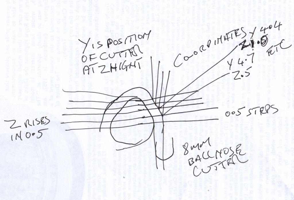
Rough sketch but the principle should be clear.
The Z height is stepped at say 0.5mm the Y is where the 0.5 intersects with the path of
the 8mm ball nose.
If you move the cutter to these co-ordinates and take a cut, you will generate the cam. You can start at the top or bottom of the cam, does not matter which.
The path is for the centre of the ball, if working manually the Z will be 4mm lower.
If using CNC, allow the 4mm in length compensation.
.  Edited By David Clark 1 on 30/06/2011 19:33:06 Edited By David Clark 1 on 30/06/2011 22:16:40 |
| Roderick Jenkins | 01/07/2011 08:48:50 |
 2376 forum posts 800 photos | Steve, As Jason B says, visit Ron's site from the link -use the mk2 version. I wrote the original SIC article and program, first in GW-basic and then in Q-basic both of which are DOS programs. The Qbasic version still runs under Windows XP, though in a rather small window. I have converted the programs into an Excel spreadsheet. PM me if you would like a copy. If you have CAD then you can draw the cam and then draw a series of lines radially from the base circle centre at 3 degree intervals (using a polar array). You can then read off the co-ordinates of the intersection of the radial lines with the cam profile. This will give you the Z setting for the mill against the rotation from a dividing head cheers, Rod |
| Styx | 05/07/2011 07:56:37 |
34 forum posts 42 photos | Rod, Dave and Jason,
Thanks for all the tips, plenty for me to think about.
Steve.... |
| Gaspode | 19/08/2011 14:30:39 |
| 8 forum posts | I met a guy at one of the shows a few years ago who had made a kind of pantograph type arrangement for tracing the outline of a full-size cam and moving the scale cam against the cutter in the same shape.
<pause for a quick bit of googling>
The guy's name is Invar Dahlberg, the model was a Mercer Raceabout, and the tool was used against a grinder - see http://www.craftsmanshipmuseum.com/dahlberg.htm
HTH |
| Gaspode | 19/08/2011 14:30:48 |
| 8 forum posts | I met a guy at one of the shows a few years ago who had made a kind of pantograph type arrangement for tracing the outline of a full-size cam and moving the scale cam against the cutter in the same shape.
<pause for a quick bit of googling>
The guy's name is Invar Dahlberg, the model was a Mercer Raceabout, and the tool was used against a grinder - see http://www.craftsmanshipmuseum.com/dahlberg.htm
HTH |
| JasonB | 19/08/2011 16:52:42 |
25215 forum posts 3105 photos 1 articles | This is one I did the other week using the mill method, bit of an odd shape as it needs to work an ignitor as well as the exhaust valve.
 Model Engien Builder mag has been running a series with a cam grinding jig that has a follower that runs on a master or template and then produces the actual cam from that. Basic 3D image here J Edited By JasonB on 19/08/2011 17:08:01 |
| Flywheel | 19/08/2011 18:26:12 |
| 34 forum posts 1 photos | Hi Steve
Google CamCalc then type in your known figures for your cam, press calculate and the program will work it all out for you
regards |
| JasonB | 19/08/2011 18:36:32 |
25215 forum posts 3105 photos 1 articles | Joseph, the link I posted back in June takes you to Camcalc and the newer Mk 2 version
|
| Windy | 19/08/2011 19:44:44 |
 910 forum posts 197 photos | Hello Steve
This link Software for People Who Build Things!
There is a program on cams also many other interesting ones that might be of use to model engineers. Windy Edited By Windy on 19/08/2011 19:45:56 |
Please login to post a reply.
Magazine Locator
Want the latest issue of Model Engineer or Model Engineers' Workshop? Use our magazine locator links to find your nearest stockist!
Sign up to our Newsletter
Sign up to our newsletter and get a free digital issue.
You can unsubscribe at anytime. View our privacy policy at www.mortons.co.uk/privacy
Latest Forum Posts
- *Oct 2023: FORUM MIGRATION TIMELINE*
05/10/2023 07:57:11 - Making ER11 collet chuck
05/10/2023 07:56:24 - What did you do today? 2023
05/10/2023 07:25:01 - Orrery
05/10/2023 06:00:41 - Wera hand-tools
05/10/2023 05:47:07 - New member
05/10/2023 04:40:11 - Problems with external pot on at1 vfd
05/10/2023 00:06:32 - Drain plug
04/10/2023 23:36:17 - digi phase converter for 10 machines.....
04/10/2023 23:13:48 - Winter Storage Of Locomotives
04/10/2023 21:02:11 - More Latest Posts...
- View All Topics
Support Our Partners


Shopping Partners
Subscription Offer

Latest "For Sale" Ads
- Reeves** - Rebuilt Royal Scot by Martin Evans
by John Broughton
£300.00 - BRITANNIA 5" GAUGE James Perrier
by Jon Seabright 1
£2,500.00 - Drill Grinder - for restoration
by Nigel Graham 2
£0.00 - WARCO WM18 MILLING MACHINE
by Alex Chudley
£1,200.00 - MYFORD SUPER 7 LATHE
by Alex Chudley
£2,000.00 - More "For Sale" Ads...
Latest "Wanted" Ads
- D1-3 backplate
by Michael Horley
Price Not Specified - fixed steady for a Colchester bantam mark1 800
by George Jervis
Price Not Specified - lbsc pansy
by JACK SIDEBOTHAM
Price Not Specified - Pratt Burnerd multifit chuck key.
by Tim Riome
Price Not Specified - BANDSAW BLADE WELDER
by HUGH
Price Not Specified - More "Wanted" Ads...
Get In Touch!
Do you want to contact the Model Engineer and Model Engineers' Workshop team?
You can contact us by phone, mail or email about the magazines including becoming a contributor, submitting reader's letters or making queries about articles. You can also get in touch about this website, advertising or other general issues.
Click THIS LINK for full contact details.
For subscription issues please see THIS LINK.
Digital Back Issues


Donate

 Register
 Log-in
Model Engineer Magazine
- Percival Marshall
- M.E. History
- LittleLEC
- M.E. Clock

ME Workshop
- An Adcock
- & Shipley
- Horizontal
- Mill

Subscribe Now
- Great savings
- Delivered to your door

Pre-order your copy!
- Delivered to your doorstep!
- Free UK delivery!
All Forum Topics > I/C Engines > Machining cam lobes