Forum sponsored by:

Travelling Steady.
| Geoff Causon | 08/03/2011 09:33:58 |
| 16 forum posts 6 photos | Hope someone can help.
I have "upgraded" to an asian lathe which came with fixed & travelling steadies. My next project needs leadscrews, which obviously require the travelling steady. My problem is, how do I line up the cutting tool with the fingers?
Harold Halls excellent article simply says "use the compound slide".
When I rotate the compound to the 29.5 deg angle this is not an option. Even worse, I have replaced the 4way toolpost with a quickchange one, This results in the steady fingers being about 50mm behind the tool.
I am about to make a new steady, have I missed something? |
| Dusty | 08/03/2011 10:02:49 |
| 498 forum posts 9 photos | Geoff
Could you post a photograph of your setup, I am afraid I cannot envisage why the tool is that far in front of the steady. Convention says that the fingers should be slightly in front of the tool i.e. closer to the chuck. |
| Steve Garnett | 08/03/2011 10:27:41 |
| 837 forum posts 27 photos | I think I can see why this is - and also what you may have missed. I'm assuming that you've rotated the compound clockwise, which invariably takes the cutting edge of the tool further away from the LHS of the cross-slide, where presumably your travelling steady is. What you have to do at this point is to rotate the quick-change toolpost anti-clockwise so that it's facing directly towards the work again. This will bring the tool tip back towards the steady, but still allow you the oblique feed in. The other question is - have you got the correct 29.5 degrees? According to the Martin Cleeve book this would be 29.5 degrees anticlockwise from the direction that the cross-slide travels in - and that looks like quite a steep angle, rather than just a 29.5 degree clockwise rotation from its customary position. In fact it would be 60.5 degrees from that. But regardless, the toolpost should still be rotated in the opposite direction to realign it into its conventional position. If you have access to the book, there's a good drawing of what the cutting setup should look like at the start of chapter 8. |
| Steve Garnett | 08/03/2011 10:35:17 |
| 837 forum posts 27 photos | I found a page which shows what the compound slide arrangement should look like - scroll down to about the 6th to 8th pictures: |
| Geoff Causon | 09/03/2011 06:18:08 |
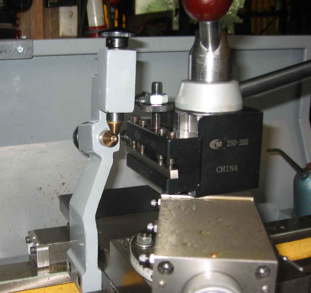
| 16 forum posts 6 photos | Thanks for your help. Photos' attached will explain better.
I tried swinging the compound to the left as Steve suggested & the tool lines up perfectly at 30 deg & is 6mm ahead of the fingers at 15 deg.
I have never cut a thread backwards before but it should work ok. In fact, it means I can run the tool off the part at the tailstock end. This will be good for my heart rate as disengaging the half nuts before crashing into the shoulder at the headstock end is always exciting.
I guess if I want to use the steady for parallel turning I can swing the compound to line up the tool. It would not be possible to have the fingers lead the tool, but I doubt I would ever need that.
Re: 29.5 deg;
We both mean the same thing. My 29.5 deg is after swinging the compound 90 deg, then back 29.5. ( or now an extra 29.5)
|
| Terryd | 09/03/2011 06:54:31 |
 1946 forum posts 179 photos | Hi Geoff, it is more normal to set the angle of the top slide the other side of the 90 degree mark to allow a forward feed of the tool. Your toolpost could be rotated and effectively reversed. Also would it not be possible to insert a spacer block between the steady and the body of the slide to move it further forward Just a couple of observations Regards Terry |
| Dusty | 09/03/2011 09:16:55 |
| 498 forum posts 9 photos | Hi Geoff,
If you are going to parallel turn with a travelling steady then the fingers must lead the tool for the following reasons.
a. It is almost impossible to set the fingers to trail the tool
b. If set to line up with the tool the burr thrown up by the tool will tear the fingers to pieces and make them useless. The same applies to screwcutting.
I think Terry's idea of a spacer is the most practical.
I wish you luck. |
| Steve Garnett | 09/03/2011 09:45:19 |
| 837 forum posts 27 photos | Terry, in Geoff's pictures he seems to have shown the compound offset in both directions! But if, as he says, he is cutting reverse threads then wouldn't the unconventional offset be the correct one in terms of advancing (or is it retarding?) the cut? As well as the things Dusty mentions, the other problem with using a steady in line with the cut is that to all intents and purposes, the steady doesn't steady the work any more, because it is at that point that the work's diameter is changing - and the steady loses contact with it. |
| RichardS | 09/03/2011 10:00:30 |
| 33 forum posts | For a travelling steady, a point to remember - when turning round stock the fingers lead the tool anything else, the fingers trail the tool. |
| KWIL | 09/03/2011 10:18:35 |
| 3681 forum posts 70 photos | The pictures look OK to me for LH screwcutting with the carriage moving left to right. The problem of the fingers and changing diameter does not occur with screwcutting, because, hopefully the overall daimeter is not changing. Just have the fingers wide enough to cover the pitch! |
| KMP | 09/03/2011 10:30:17 |
| 73 forum posts 2 photos | Geoff Hi,
As has already been said, the fingers need to lead the tool when cutting. In your example the QCTP is the problem as it allows very little angle change of the tool bit. One would normally rotate the tool post round its' mounting bolt and regain the 90 deg (to work axis) by offsetting the tool in the holder. Yours will not provide sufficient offset for this to work. This is one example of where the old fashoned clamp type holder is an advantage.
In your case the normal way would be to use a 90 deg thread cutting tool with the QCTP set so that the holder is parallel with the work axis and the tool can be set forward or back in the tool holder to change its' position relative to the fingers. When you turn the tool post 90 deg you can decide if you need a right hand or left hand 90 deg threading tool. On some of the QCTP holders you will find two holes accross the end of the holder to hold the tool at 90 deg. On yours you could make a simple T piece with a slot on the outside of the top of the T and a couple of set screws to hold your tool at 90 deg. This method is standard practise but does mean you have to be very careful that clearance exists for the entire thread length and it is easy to run something into the chuck or the tailstock.
Hope this helps
Keith |
| Nicholas Farr | 09/03/2011 10:51:56 |
 3988 forum posts 1799 photos | Hi Geoff, I think I'd do what Terry suggests and try a spacer to pack your steady forward. That way you wont have to much more expense. Shouldn't take to much to make, but you may need longer screws of course.
Regards Nick. Edited By Nicholas Farr on 09/03/2011 10:53:05 |
| Nicholas Farr | 09/03/2011 11:06:03 |
3988 forum posts 1799 photos | Hi Geoff, also if it is setup like your secound picture and run towards the tail stock, like Kwil says you will have a lefthand thread, unless you turn your tool upside down and reverse the direction of the spindle.
Regards Nick. Edited By Nicholas Farr on 09/03/2011 11:07:03 |
| Terryd | 09/03/2011 11:31:13 |
1946 forum posts 179 photos | Posted by Steve Garnett on 09/03/2011 09:45:19: Terry, in Geoff's pictures he seems to have shown the compound offset in both directions! But if, as he says, he is cutting reverse threads then wouldn't the unconventional offset be the correct one in terms of advancing (or is it retarding?) the cut? Hi Steve, I hadn't really noted that in the original post as I was still trying to get my head round the description. Regarding my comment about angle I was just trying to suggest that the first picture was the correct one, just in case of confusion. A simple spacer block would push the travelling steady forward sufficiently I would have thought Is he cutting a LH thread? Or as Nick says is the spindle to be reversed with the tool inverted? Terry  |
| Steve Garnett | 09/03/2011 20:32:34 |
| 837 forum posts 27 photos | Posted by Terryd on 09/03/2011 11:31:13: Is he cutting a LH thread? Or as Nick says is the spindle to be reversed with the tool inverted? Terry Well, in his second post (the one with the pictures), Geoff does say "I have never cut a thread backwards before but it should work ok." So I was assuming from this that he was! On top of that, he's indicated that it's for a leadscrew, and they generally are, aren't they? If it's a normal sort of thread diameter, I would have hoped that the steady would have made adequate contact with the work, but I can see why you think that it might need a bit of help, certainly in one picture. In the other one it looks fine, though. Maybe Geoff can elucidate? |
| Nicholas Farr | 09/03/2011 21:43:05 |
3988 forum posts 1799 photos | Hi Terry and Steve, in Geoff's post with the photos, part of what he says; "I can run the tool off the part at the tailstock end" that's why I think he may go from left to right, because he goes on to say about it being good for his heart, because he sounds anxious about disengaging moving towards the headstock.
I wonder if Geoff realises he will cut a LH thread going towards the tailstock with the spindle in the foward direction.
Like you say Steve, maybe Goeff will elucidate.
Regards Nick. |
| Geoff Causon | 10/03/2011 09:37:16 |
| 16 forum posts 6 photos | Embarassingly, I was so focused on the LH part I missed what you all saw. With the compound angled to the left I can only make LH threads but I also need RH parts.
I guess I am back where I started.
The problem seems to be the large offset toward the tailstock on the steady casting, as all the pictures I see of steadies show approximately "straight" castings.
I can use the existing steady for the LH parts, & will need to make a "straighter" body for the RH parts.
Obviously, summarising the collective wisdom above, the new steady also needs to let the fingers lead the tool if turning parallel. It almost needs to be adjustable .
Thanks everyone for your help.
|
| mgj | 10/03/2011 13:48:50 |
| 1017 forum posts 14 photos | You could always use the original toolholder/toolpost for a one off job. That would remove a pile of front overhang and probalby align the tool with with the travelling steady. I'm assuming that QCTP is not original. If it is then I apologise. If it is original, the one could always make a temporary toolholder. Block of steel/cast iron (LSM do 3" thick hunks of cast) drill for the stud, drill through from the lathe spindle, rotate 90deg and insert a made up tool. To screwcut you don't HAVE to incline anything. I never do - though I used to, but it offers no particular advantage. A decently ground tool with a touch of side rake will produce a better finish to the threads CLA, because the trailing edge has no steps in it. If you need to ease cutting pressure, you can move the topslide back and forth .001 about the helix CL. You should make a correction to the tool included angle if you use rake, but for a few degrees its so small as to be within the clearance in the nut. You could very easily disppose of tha\t steady altogether and use something more akin to the small dia combined steady/cutter holders. With them the tool is movable in hte holder. however to make one is bit of hassle for a one off. So, you have studs locking up the tool sticking out of the tool holder. Use them to hold down a plate with a short tube of the right dia which you can then arrange to lead the tool (desirably), or trail it a touch if you are going up to a shoulder. You'll need to pack it quite accurately or you could do some measurements and it will fit in one.You will need slots to allow for tool infeed and have to adjust inbetween each cut.. Or you could mount a similar setup off the locking/mounting bolt for the topslide. Then you woulnd need ot adjust for infeed because that bit won't move. That might be better than bronze steady fingers which have a habit of gooving with the thread and then "take" the saddle forwards If I may say so we have all made a hell of meal of a very simple problem, and we have all been fixed on solving a problem, without looking at what is required. What we need to do is support the job, with a minimum of fuss and trouble . The problem we have looked at is how to modify/move a steady. There is, I believe, a difference?. Edited By mgj on 10/03/2011 13:52:16 |
| Terryd | 10/03/2011 14:05:55 |
1946 forum posts 179 photos | Posted by mgj on 10/03/2011 13:48:50: If I may say so we have all made a hell of meal of a very simple problem, and we have all been fixed on solving a problem, without looking at what is required. What we need to do is support the job, with a minimum of fuss and trouble . The problem we have looked at is how to modify/move a steady. There is, I believe, a difference?. Edited By mgj on 10/03/2011 13:52:16 hi Meyrick, I wouldn't have thought that couple of holes in a suitable piece of BDMS to make a spacer was that complicated a solution. Much simpler than jury rigging a "plate with a tube........" and the bronze fingers could do their job properly by supporting the material to be cut rather than a thread. With due regard Terry |
| mgj | 10/03/2011 19:11:50 |
| 1017 forum posts 14 photos | Well perhaps Terry - but you know what I mean - we have been looking at the steady and not the task. Bear in mind that he is cutting a leadscrew of some sort which implies a length. So the bronze fingers will bear on a thread, with all the PITA that goes with it, because the fingers should be pretty much level with the leading edge of the tool - to get the three points of contact at the point of the cut. One should only lead or trail if it is necessary or convenient to do so - the optimum support comes when the fingers straddle the cut - only possible when screwcutting of course. |
Please login to post a reply.
Magazine Locator
Want the latest issue of Model Engineer or Model Engineers' Workshop? Use our magazine locator links to find your nearest stockist!
Sign up to our Newsletter
Sign up to our newsletter and get a free digital issue.
You can unsubscribe at anytime. View our privacy policy at www.mortons.co.uk/privacy
Latest Forum Posts
- *Oct 2023: FORUM MIGRATION TIMELINE*
05/10/2023 07:57:11 - Making ER11 collet chuck
05/10/2023 07:56:24 - What did you do today? 2023
05/10/2023 07:25:01 - Orrery
05/10/2023 06:00:41 - Wera hand-tools
05/10/2023 05:47:07 - New member
05/10/2023 04:40:11 - Problems with external pot on at1 vfd
05/10/2023 00:06:32 - Drain plug
04/10/2023 23:36:17 - digi phase converter for 10 machines.....
04/10/2023 23:13:48 - Winter Storage Of Locomotives
04/10/2023 21:02:11 - More Latest Posts...
- View All Topics
Support Our Partners


Shopping Partners
Subscription Offer

Latest "For Sale" Ads
- Reeves** - Rebuilt Royal Scot by Martin Evans
by John Broughton
£300.00 - BRITANNIA 5" GAUGE James Perrier
by Jon Seabright 1
£2,500.00 - Drill Grinder - for restoration
by Nigel Graham 2
£0.00 - WARCO WM18 MILLING MACHINE
by Alex Chudley
£1,200.00 - MYFORD SUPER 7 LATHE
by Alex Chudley
£2,000.00 - More "For Sale" Ads...
Latest "Wanted" Ads
- D1-3 backplate
by Michael Horley
Price Not Specified - fixed steady for a Colchester bantam mark1 800
by George Jervis
Price Not Specified - lbsc pansy
by JACK SIDEBOTHAM
Price Not Specified - Pratt Burnerd multifit chuck key.
by Tim Riome
Price Not Specified - BANDSAW BLADE WELDER
by HUGH
Price Not Specified - More "Wanted" Ads...
Get In Touch!
Do you want to contact the Model Engineer and Model Engineers' Workshop team?
You can contact us by phone, mail or email about the magazines including becoming a contributor, submitting reader's letters or making queries about articles. You can also get in touch about this website, advertising or other general issues.
Click THIS LINK for full contact details.
For subscription issues please see THIS LINK.
Digital Back Issues


Donate

 Register
 Log-in
Model Engineer Magazine
- Percival Marshall
- M.E. History
- LittleLEC
- M.E. Clock

ME Workshop
- An Adcock
- & Shipley
- Horizontal
- Mill

Subscribe Now
- Great savings
- Delivered to your door

Pre-order your copy!
- Delivered to your doorstep!
- Free UK delivery!
All Forum Topics > Model Engineers' Workshop. > Travelling Steady.