Forum sponsored by:

The HobbyMat BFE 65 again
A burnt out something or other
| Sam Stones | 12/07/2010 05:38:45 |
 922 forum posts 332 photos | Hello again, especially those of you who `know’ this machine.
In passing, I’m proud to say that I’ve managed to produce some tiny clock parts on the HobbyMat lathe. The smallest is little bigger than a grain of rice but less complicated in a genetic sense, if you get my drift.
Before I introduce the main problem, I need to pass on the following comments :- This morning, once the sun in Melbourne was warming up the garage, I decided to venture into the realms of milling on the BFE 65. Full of optimism, I discovered that the optical illusion (through my reading glasses) was not an illusion after all. You know the occasion when instinctively, you figure something is wrong but can’t think what. Anyway, I was about to cheat a little by using the four-way tool post to hold a square brass bar as opposed to using the HobbyMat vice which was not the most precise and needed a good clean to boot. While setting up ready to reduce the brass in thickness using the mill, I looked more closely at the top slide, the one which has featured in a previous thread posting. I had also planned to machine a couple of angled faces via this slide. The rotary bracket was set to zero as it should be, but something was out. By sighting the top-slide with the body of the machine, I could see that the slide was skewed. Getting to the point, my dial-indicator showed that when the slide was set parallel to the machine bed, the deeply scribed marker was out by more than 1 deg !!! I had planned to cut a 2 deg taper on a clock arbor (without thinking about any possible error). Glad I didn’t try. I also remembered that accurate (in this case conical) tapers should be set up using a dial indicator over a measure length. With this sorted, I was soon relaxing again and merrily into milling the brass bar. Suddenly, the milling head motor stopped. I hit the STOP button, thinking it had tripped due to possible over-heating (I understand that this machine has not been used for some considerable time). The motor was quite cool. I tried the START button again, but was greeted with a groan at mains frequency, and no rpm. "Dear me!" I said to myself. Actually, the words were a bit stronger. "The capacitor on the motor has burnt out!", hoping it wasn’t a winding that had gone. So I need your help please. I have a multi-meter so, to check for things like coil failure, should I be measuring coil resistance at the main terminals? There’s a simple circuit diagram inside the terminal box on the motor which shows how five terminals are connected. What values should I expect? Would the capacitor be open circuit or a dead short?
Any help you can give me would be most useful.
Thanking you in advance. |
| John Olsen | 12/07/2010 10:57:14 |
| 1294 forum posts 108 photos 1 articles | Cpacitors should measure open circuit, although witb an analog meter you can often see a kick of the needle when first connected to the meter, as the capacitor charges up. Windings should show continuity end to end. You are not very likely to be able to detect any shorted turns with a meter. The normal resistance will tend to be fairly low, a few ohms sometimes, and any change due to shorted turns is minimal. However a sudden stop while running sounds more like either a winding has gone open, or the capacitor has gone short. I suppose a winding could have gone down to ground but you would expect a fuse to go then. Usually shorted turns in the motor would be accompanied by heat, smoke, and smell. The motor would often still run, albeit poorly. Some motors kindly provide a one time thermal overload buried in the winding, which stops it setting fire to things but of course is not designed to be replaced. regards John |
| Steve Garnett | 12/07/2010 11:11:23 |
| 837 forum posts 27 photos | Posted by Sam Stones on 12/07/2010 05:38:45: I doubt if it's electrical at all - the Hobbymat mills are generally fitted with nylon gears, and these have a reputation for slipping on their bushes, and locking the drive train. According to Tony on the Lathes site, just waggling the controls and jiggling the shaft backwards and forwards again is generally enough to free them. The general advice is to take the covers off and locktite the gears to the bushes - then it doesn't happen any more. This gear issue is one of the things that put me right off getting the milling attachment for the Hobbymat at all, in fact... As for the cross-slide angular calibration, I'd say that it's no worse than any other small lathe with a similar arrangement. The small steps are 2 degrees, and a simple calculation will reveal that even if you get the setting 1/10 of a degree out, you will end up with several thou error over the cross-slide travel. So if you want to set it anything like accurately then you pretty much have to clock it - just as you would with any other lathe. |
| john swift 1 | 12/07/2010 11:21:03 |
 318 forum posts 183 photos | Hi Sam ,
I don't have any machines with a single phase motor , so i can't give you exact values to measure , but I would expect the main winding to be about 10 ohms
on motors without a centrifugal switch the second winding to be around the same resistance
with a centrifugal switch about 20 ohms or so
with a multimeter on the high resistance range the capacitor should be shown as a low resistance at first , then climb to tens of meg ohm as the capacitor charges
to test for the odd shorted turn you will need some thing like the ring tester as in
silicon chip magazine a few years ago.
more expensive multimeters will measure the capacitance
unless the green's have stopped the sale of all tungsten gls bulbs in your part of the world
you could try connecting a 15W or 25W GLS bulb in series with the capacitor
I would expect a low wattage bulb to light , but not a full brightness
that way you can test it's not short circuit at mains voltages ( it may be OK at 9v from a multimeter)
without the circuit diagram i can not be more precise
If you need more help send me the circuit diagram and a hint as to what test equipment are using and I'll see what else I can do
John Swift
|
| Sam Stones | 13/07/2010 22:27:18 |
922 forum posts 332 photos |
Thank you - John O, Steve, and John S. Your combined advice is much appreciated, and I trust will be of help to others too. Further investigations of the BFE 65 reveal the following :- To confirm that twisting the quill by hand is getting through to the motor (it felt as if it was), I removed the fan cowl. I can see the motor turning (forwards or backwards), while twisting the quill in any gear . This, I have presumed, rules out the gearbox, but such a simple test was well worth investigating. Thanks Steve. I also took a risk and tried a quick spin of the quill by hand while stabbing the START button. Nothing! Other than pressing the START button a few more times, I haven’t carried out any other tests, choosing to continue using the lathe for some very basic milling and then filing parts to shape. Tiny clock parts in brass are my number one priority. However, the `growl’ response which I mentioned is emanating from the motor, and for what it’s worth is quite low in volume. What I don’t understand is the random `pulsing’ I can hear coming from behind the START/STOP panel when I hold the START button in for a few seconds. Also, why doesn’t the starter switch latch anyway? Does latching only take effect from the motor current? Sorry, the only circuit diagram I have seen is on a label inside the lid of the terminal box. If this is of any use, I’ll photograph it and add it to my postings. Is the above sufficient for a remote diagnosis? I welcome any comments. By the way Steve, I’m inclined to follow your choice regarding plastics. Although I’ve been in the plastics industry since 1950, I would shy away from buying a machine with plastic gears, especially when the demand could include severe shock loading. Although not exclusive, there’s a particular weakness which dogs the plastics industry in almost any form (FRP to a lesser degree). It’s called notch sensitivity, a predominant phenomenon emanating from toolrooms producing injection moulds. Additionally, there’s ESC (environmental stress cracking). Now perhaps I’ve opened another `tin-of-worms’? Thanks again, Sam |
| john swift 1 | 14/07/2010 00:07:41 |
318 forum posts 183 photos | Hi Sam ,
tomorrow i'll post a few simple diagrams for the start stop circuits an motor reverse circuits
If you post the circuit diagram you have i'll adapt one for your machine
the non latching of the start switch is a clue
once you have proved the motor is not passing an abnormal current
you need to take a closer look at the switches
the start switch should latch on without the motor connected
John Swift |
| Sam Stones | 14/07/2010 04:06:48 |
922 forum posts 332 photos |
Hi John, Thanks for your very prompt reply. Although the titles may not match my text, here are a few notes about each picture :- 5511---Terminal-block The blue and brown wires (bottom right of picture) come from the capacitor. The brown wire is connected to U1, the blue wire is connected to Z1. (See 5516---Terminal-connection-diagram) The blue and brown wires (bottom left of picture) come from the bottom of the circuit breaker. The striped leads disappear into the motor.
5512---Capacitor-detail Although not the best image, the capacitor has values of 40mF/320V printed on the side. Is the case simply earthed for safety reasons via the clamp? 5513---START-STOP-&-Circuit-breaker (& 5514, 5515)The mains and earth, enter the circuit via the white 3way terminal block (in the middle of 5513). The top switch is behind the START button. Presumably N.O. (Normally Open) The lower switch above the white 3way terminal block is behind the STOP button. Presumably N.C. (Normally Closed) The bottom (green/blue) block is obviously the starter solenoid. Although unclear in the photograph, the black wire at the rear of the shot, loops top to bottom terminals of the solenoid block. At the very top, there’s a black circular gadget with three terminals and a preset (locked) grub screw. Not sure what this does, but presume it’s in the solenoid coil circuit and forms part of the latching and perhaps thermal overload? Two leads (brown and blue) from the underside of the contact breaker are connected to the terminal block. Blue to U1 and brown to U2. Refer to 5511 I now realise that the two circuit diagrams inside the cover are simply for motor direction. However, neither diagram seems to match the actual layout. I can’t see a need for a milling machine to run backwards.
Sorry about depth of field. I can take better images if needed. Thanks a million. Sam |
| Sam Stones | 14/07/2010 04:42:12 |
922 forum posts 332 photos | Hi John,
Immediately after returning everything to its place, I plugged in and pressed the START button.
THE MOTOR SPUN FOR A COUPLE OF TURNS AND THEN STOPPED!
I tried once more, and the quill turned slightly.
Does this help?
Regards,
Sam
PS Would this be better sorted by direct email? |
| Sam Stones | 14/07/2010 05:52:12 |
922 forum posts 332 photos | I omitted to say that the pulsating growl when holding down the START button, is coming from behind the START/STOP button. Probably from the circuit breaker solenoid. |
| joegib | 14/07/2010 10:18:59 |
| 154 forum posts 18 photos | If it's of any help this is the electrics diagram from the manual:
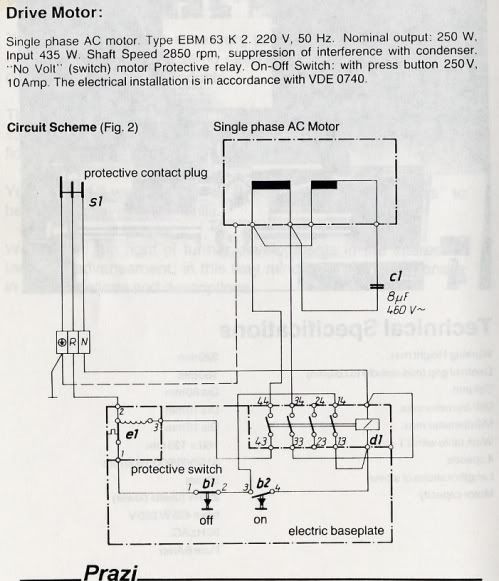 (Click on image to enlarge) I should say this is described as the lathe motor circuit/control system but since the mill motor set-up is not separately shown, I believe the latter is exactly the same electrically.
The full manual is available from the Prazi Yahoo newsgroup here:
in the 'Files' section --> 'BF400 Manual'. Unfortunately, to get access you need to join the group and that can be a problem. The administration of the group is unreliable so it may take a week or two for the membership to be registered. It can take that long for a post to appear!. But it's worth trying so as to get access to useful material.
I'll leave it to the electroheads to comment on the implications.
 Joe
Edited By joegib on 14/07/2010 10:23:14 Edited By joegib on 14/07/2010 10:24:30 Edited By joegib on 14/07/2010 10:25:55 Edited By Katy Purvis on 01/06/2015 11:49:53 |
| Sam Stones | 14/07/2010 11:41:01 |
922 forum posts 332 photos | Many thanks Joe.
One of your attachments wouldn't show, but the Prazi circuit diagram will be very useful.
From this diagram, and the symptoms I'm beginning to think that the `protective' switch may have something to do with the start/running of the motor, and preventing latching. I'll wait until the `electroheads' as you call them, have read my more recent posts, and have had a chance to look at yours.
In passing, and for the benefit of the others contributing to this thread, I have to say that the growl I mentioned is a fairly quiet mains frequency groan (hum). The pulsing I've mentioned is just audible above the level of the 50Hz hum, and seems to affect, (dare I say) modulate it.
Thanks again,
Sam
Edited By Sam Stones on 14/07/2010 11:44:15 Edited By Sam Stones on 14/07/2010 11:52:35 |
| john swift 1 | 15/07/2010 03:01:24 |
318 forum posts 183 photos | Hi Sam,
I have scanned a few quick diagrams I hope will help
If the contactor operates when you push the start button
the overload cutout must be closed
a fault in the connections to the contactor terminals 13 & 14
or the contact is self would stop it latching on
with the mains disconnected you can push down on the top of the
contactor and check you have a low resistance when the contacts make
and across terminals 2 &3 of the overload unit - the heater coil should be low resistance
at the motor terminals check the continuity of the windings and the centrifugal switch
If your meter can check the capacitor is 40 uF
you might end up substituting it with a new one to prove if it ok or not
with the mains on the full mains should be across the motor winding U1 to U2
John Swift 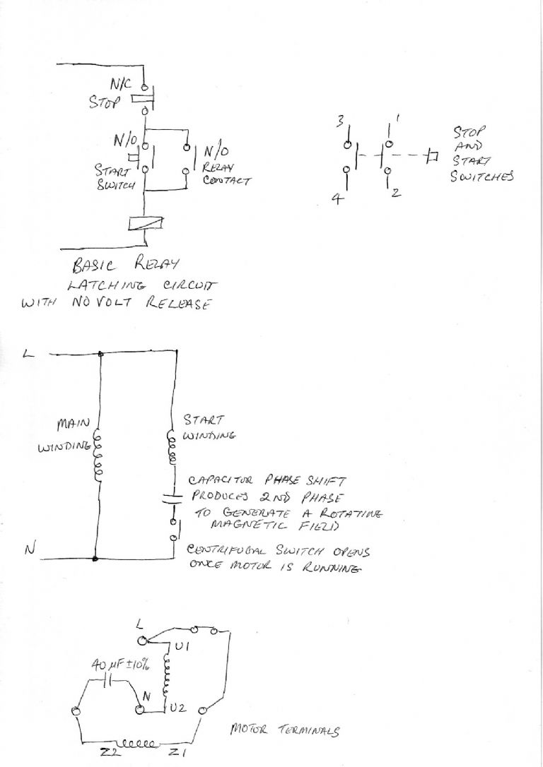 |
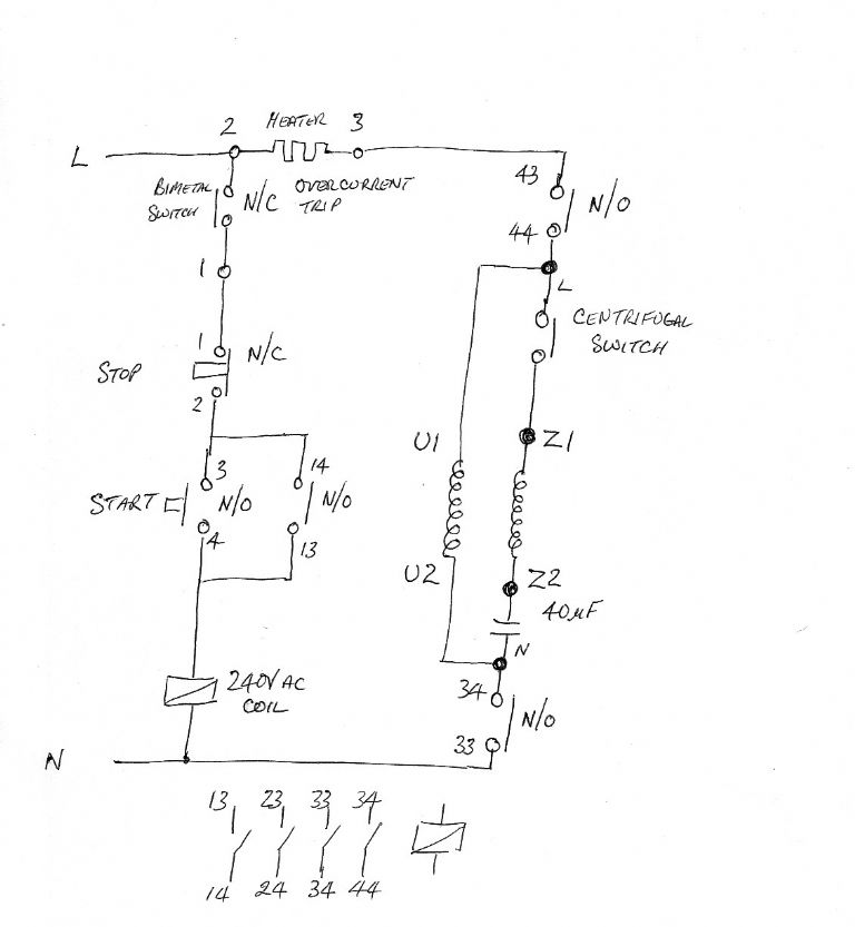
| john swift 1 | 15/07/2010 09:44:06 |
318 forum posts 183 photos | the other diagram I failed to add at 3 AM !
yesterday turned into a long day ,
I hope they are easy to follow
John
 |
| Jim Whetren | 15/07/2010 11:16:05 |
| 50 forum posts 1 photos | Hello Sam,
I don't want to go off on a tangent to what has already been said, but I would like to make an observation.
I have both a Hobbymat mill and a Prazimat lathe from the same East German manufacturer which have some similarities, for instance the large aluminium hand wheels are identical.
The mill motor looks to be a smaller version of the lathe motor. To get to the point, I had a fail to start buzz with my lathe which turned out to be the centrifugal start switch. I found that one of the contacts had disappeared, leaving one contact point and a hole in the end of a contact spring, causing the intermittent contact.
I managed to find some salvaged contacts and removed the contact point and riveted in place. The lathe has been working ever since.
Sorry for the ramble, but it was just a thought.
regards
Jim |
| Sam Stones | 15/07/2010 12:26:47 |
922 forum posts 332 photos |
Gentlemen, Thank you so much for all your advice wrt the BFE 65 mill. Those initials are getting to me, and I’ve wondered if they have a secret meaning. Any ideas? Anyway, I really appreciate getting this sort of help from you people, especially the circuit diagrams and the effort you have all put into solving my problem. Had this been my machine (its only on loan), perhaps I would have pulled it apart without hesitation. But since it isn’t, and the failure happened while I was at the helm so-to-speak, I feel obliged to get it fixed as professionally as possible. I have a couple of pieces of news. A good friend has offered to take a closer look at the electrics, and to apply various electrical tests. My guess is that he’ll have the right gear. He also pointed out that since the machine has stood around for a considerable time (information I gathered about the machine a few days ago), and has only been used a couple of times in that period, there is a strong likelihood that the capacitor has deteriorated. There are a couple of snags to this offer. For various other reasons, we will carry out the tests at his place. Also, not being as fit and tough as I used to be, lifting is becoming a "NO NO!" (That’s the wife from the kitchen). This morning I stood pondered the problem of how to get the BFE 65 mill into the back of our car without any serious lifting. Of necessity the whole unit needed to be given a straight lift upwards to extract the vertical column from the bracket attached to the back of the lathe. Years ago, as a toolmaker, I was obliged to carry out this simple (clean & jerk) movement, while splitting plastics moulds apart on the bench. Using the quill to jack the whole caboodle from its resting place, and somehow progressively insert blocks underneath turned out to be futile. However, I decided to avoid a strained back, and split the head at the swivel point, bearing in mind that those two inaccessible `T’ nuts will drop down into the wrong place when I reassemble. I’d done this `trick’ before on my Jack Jones, so I tried again and it worked a breeze. The gearbox and motor are not that heavy, so they're sitting in the back of the car ready for tomorrow’s trip. Those circuit diagrams should help a lot too. Here’s hoping for a good (final) posting and an end to this thread. Best regards, Sam |
| Nicholas Farr | 15/07/2010 12:34:43 |
 3988 forum posts 1799 photos | Hi, the circuit diagram that Joe has posted for his Prazi is exactly the same as printed in the user manual that I have for the Hobbymat BFE 65.
Regards Nick |
| Nicholas Farr | 15/07/2010 13:31:57 |
3988 forum posts 1799 photos | Hi again, the black circular gadgit that you mention is e1 on Joe's diagram and is a thermal over load that takes at least 10 seconds to reset acording to the user manual instructions.
regards Nick. |
| joegib | 15/07/2010 15:10:47 |
| 154 forum posts 18 photos | Hi Sam, Just a few final remarks: 1. Your method of disassembly is fine — for various reasons I've had my head off the machine several times and this is the way I always do it, leaving the column in situ. When you come to re-install it I suggest you place a couple of wooden blocks across the lathe bed, (after removing the gear and quill drive levers temporarily), place the head horizontally with casing resting on the blocks (say, motor to left, spindle to right and mounting ring at the back, of course), bring the head mounting block down the column, simply align the block spigot with the head mounting ring and push the head backwards onto the spigot. I haven't done this job for several years but I don't remember any special difficulty in aligning the the captive T-nuts with the Allen securing bolts. This assumes you have access to the back of the machine. If not, bear in mind that you can loosen the Allen screws in the column base casting and swing the whole assembly round to get access to the bolt holes.. In this case you must use some method to keep the head mounted on the spigot temporarily e.g strap the head to the column with holdfasts . 2. If for any reason your friend decides to separate the motor from the head, he should beware of one oddity with these machines. Normally, we all expect the key to be firmly fitted to a motor drive shaft. Not necessarily so with this machine! The key was quite loose and, oddly, extended maybe an 1/8th of an inch beyond the end of the motor shaft. Moreover, there was a fine pin through one end of the key that fitted in a corresponding hole drilled in the key seating. Maybe this is designed to stop the key dropping down into the gearbox when installing the motor vertically. Even so, it is still possible for the key to drop into the head innards if knocked on assembly so (a) the motor shaft and key should be degreased and secured using Loctite and (b) the motor should be mounted into the head horizontally. None of this may be relevant in your case if motor separation is not required. Good luck Joe Edited By joegib on 15/07/2010 15:13:00 |
| Sam Stones | 16/07/2010 00:09:15 |
922 forum posts 332 photos |
You beaudie, as they say down here in OZ. Thanks again for all your information, I’ll get back with a report shortly. Meanwhile, I’ve opened a photo album for the skeleton clock, starting with a HLR (hidden line removal) image from my KeyCreator file via Photoshop CS3. Finishing this clock is my prime target. Thanks to all. Sam |
| Sam Stones | 17/07/2010 00:49:04 |
922 forum posts 332 photos |
Good day Gentlemen, In my friend’s workshop yesterday, tests of the electrical component of the BFE 65 mill revealed several issues and anomalies. Before I continue however, I have to thank again, those ME members who, through this thread, have offered their comments. In return, I trust that the following details may be of help to others with similar experiences. A couple of theoretical (possibly trivial) aspects are noted, such as :- a) The circuit diagram show the capacitor’s value as 8mf/460V~ while the actual capacitor is rated at 40mf/320V~. I’m told that a larger capacitor may improve the motor torque a little. b) The circuit diagram shows the motor rated at 220V which immediately drew suspicion from my friend. Whenever I’ve measured our domestic supply, it has been a healthy 250V. However, the tiny motor indicator plate displays 240V.
The 40mf capacitor passed every electrical test, but started to heat up when the motor was placed directly across the mains for a few seconds, (ie bypassing the START/STOP contact breaker circuit). The motor’s insulation to earth via a high voltage test meter got an "OK!" when it showed a very high resistance. Using a current meter around single (input) wires in the motor terminal box, motor current on the two windings measured about 7amps and 5amps. We didn’t try to identify which winding was which. When the motor was removed from the gear box, the shaft could be spun by hand with no mechanical resistance. In fact, it turned very smoothly. Thanks for the warning about the loose key Joe! As you might expect, Murphy placed it face down, but we were ready. Applying mains as before, we could also hear a centrifugal switch responding to motor rpm, dropping out as it approached running speed and then back in again as it stopped. This latter issue appears to conflict with the circuit diagram which doesn’t show this switch. The presence of amperage on both windings while the motor was running suggests that the centrifugal switch is ineffectual, or for some other reason, the capacitor remains in circuit.
Was this why it began to heat up?
We didn’t get around to John Swift’s suggestion of testing the solenoid `latching’ while the motor was disconnected. However, I tried it myself this morning.
More disappointment!
It wouldn’t latch and instead, I could hear the pulsing (mains frequency) groan I mentioned before.
Prognosis - 1. Probable shorted-turns in the motor. 2. An unexplained fault in the starter circuit. I was expecting closure on this thread. Murphy should take a holiday. Thanks again for all your comments and help. Sam |
Please login to post a reply.
Magazine Locator
Want the latest issue of Model Engineer or Model Engineers' Workshop? Use our magazine locator links to find your nearest stockist!
Sign up to our Newsletter
Sign up to our newsletter and get a free digital issue.
You can unsubscribe at anytime. View our privacy policy at www.mortons.co.uk/privacy
Latest Forum Posts
- *Oct 2023: FORUM MIGRATION TIMELINE*
05/10/2023 07:57:11 - Making ER11 collet chuck
05/10/2023 07:56:24 - What did you do today? 2023
05/10/2023 07:25:01 - Orrery
05/10/2023 06:00:41 - Wera hand-tools
05/10/2023 05:47:07 - New member
05/10/2023 04:40:11 - Problems with external pot on at1 vfd
05/10/2023 00:06:32 - Drain plug
04/10/2023 23:36:17 - digi phase converter for 10 machines.....
04/10/2023 23:13:48 - Winter Storage Of Locomotives
04/10/2023 21:02:11 - More Latest Posts...
- View All Topics
Support Our Partners


Shopping Partners
Subscription Offer

Latest "For Sale" Ads
- Reeves** - Rebuilt Royal Scot by Martin Evans
by John Broughton
£300.00 - BRITANNIA 5" GAUGE James Perrier
by Jon Seabright 1
£2,500.00 - Drill Grinder - for restoration
by Nigel Graham 2
£0.00 - WARCO WM18 MILLING MACHINE
by Alex Chudley
£1,200.00 - MYFORD SUPER 7 LATHE
by Alex Chudley
£2,000.00 - More "For Sale" Ads...
Latest "Wanted" Ads
- D1-3 backplate
by Michael Horley
Price Not Specified - fixed steady for a Colchester bantam mark1 800
by George Jervis
Price Not Specified - lbsc pansy
by JACK SIDEBOTHAM
Price Not Specified - Pratt Burnerd multifit chuck key.
by Tim Riome
Price Not Specified - BANDSAW BLADE WELDER
by HUGH
Price Not Specified - More "Wanted" Ads...
Get In Touch!
Do you want to contact the Model Engineer and Model Engineers' Workshop team?
You can contact us by phone, mail or email about the magazines including becoming a contributor, submitting reader's letters or making queries about articles. You can also get in touch about this website, advertising or other general issues.
Click THIS LINK for full contact details.
For subscription issues please see THIS LINK.
Digital Back Issues


Donate

 Register
 Log-in
Model Engineer Magazine
- Percival Marshall
- M.E. History
- LittleLEC
- M.E. Clock

ME Workshop
- An Adcock
- & Shipley
- Horizontal
- Mill

Subscribe Now
- Great savings
- Delivered to your door

Pre-order your copy!
- Delivered to your doorstep!
- Free UK delivery!
All Forum Topics > Beginners questions > The HobbyMat BFE 65 again