Forum sponsored by:

Alignment of lead screw on CL300
| Anthony Knights | 05/06/2010 00:31:16 |
| 681 forum posts 260 photos | I recently removed the lead screw on my CL300 lathe to drill the tailstock end to fit an extension shaft (a la Dave Fenner) When refitting, I found that as I tightened the screws on the bearing at the headstock end, the leadscrew became progressivly stiffer, until, withe block fully fitted, I could not turn the leadscrew with my fingers. Could this be the reason for the change in motor noise when the leadscrew was engaged ? This had been something I had noticed since I first got the machine, but just assumed that it was normal.
Decided that the problem was due to some sort of mis-alingment of the leadscrew bearings. Having contemplated the problem with a can of lager,
I then cut some shims from said can (probably the best shims in the world) and tried fitting them.Two shims seemed to do the trick.
I do have Mr. Fenners excellent book on the Mini Lathe and have explored numerous websites dedicated to these machines. I have not found the above problem mentioned any where and would appreciate any constructive comments from anyone, as to the problem or my solution. |
| Gone Away | 05/06/2010 00:43:09 |
| 829 forum posts 1 photos | Did you engage the carriage feed-lever before tightening the bearings? |
| Michael Cox 1 | 05/06/2010 04:36:37 |
| 555 forum posts 27 photos | Your CL300 is a Seig 7 x 12 machine. If you look on the Yahoo 7 x 12 minilathe groupyou will find that this problem is always turning up. Shimming is the way to go to correct the problem as you have discovered. However, the distance of the apron from the leadscrew must remain constant along the whole legth of the lathe bed. You can check this by engaging the half nuts at both ends of the bed. The half nuts should engage easily at both ends (and in the middle) without causing the leadscrew to deflect significantly. If it does deflect then you have to play with the shimming until there is no deflection. Sometimes it is necessary to shim only one side of the pillow blocks in order to get both bores to be "in line".
Mike |
| Anthony Knights | 08/06/2010 00:18:25 |
| 681 forum posts 260 photos | Hi Sid,
as you have to open the half nuts in order to install the lead screw, the answer to your question is NO. The correct method (if you believe what I have read) is to fit the lead screw, slacken the screws holding the apron,THEN engage the half nuts (which is supposed to pull everything into alignment), then tighten the apron screws. |
| Gone Away | 08/06/2010 01:38:12 |
| 829 forum posts 1 photos | Hi Anthony, Well, what I actually said was to engage the carriage feed lever before tightening the bearings - not before installing the leadscrew (obviously). I was assuming the leadscrew was in place. You also need to have the carriage close to the bearing when you do that. It was merely that it's often forgotten and if you don't have the half-nuts engaged close to each bearing when tightening it there will almost certainly be problems. What I do is actually work back and forth a bit between the apron screws and the bearing screws thus: - start of with the screws of both bearings and the apron slightly loose. - set the carriage half way along the leadscrew, engage half nuts, nip up the apron screws. - traverse to extreme right, engage half-nuts, tighten right bearing. - traverse to extreme left, engage half-nuts, tighten left bearing. - centre carriage, engage half-nuts slacken and then tighten apron screws - traverse to extreme right, engage half-nuts, slacken then tighten right bearing. - traverse to extreme left, engage half-nuts, slacken then tighten left bearing. Edited By Sid Herbage on 08/06/2010 01:45:09 Edited By Sid Herbage on 08/06/2010 01:49:03 |
| Anthony Knights | 10/06/2010 20:41:20 |
| 681 forum posts 260 photos | Hi Sid,
it's me again (Anthony). We appear to be working at cross purposes here. I appreciate you explaining how to align the lead screw with the half nuts, but my problem is somewhat different. There is some inaccuracy with either the bearing blocks themselves, or the places they are mounted. This means that when they are bolted down the normally straight lead screw is being bent into a banana shape. No amount of adjusting is going to correct this without shimming the blocks so that their axies are in line.
This weekend I intend stripping the whole lot down again and checking the bearing blocks for accuracy. I will also make a shoe for the DTI lever so it surfs the top of the leadscrew threads and clock the whole length of it from the saddle. I will report back later.
Regards Anthony
|
| Gone Away | 10/06/2010 21:43:05 |
| 829 forum posts 1 photos | Hi Anthony, Well .....as long as you are sure that the problem is really caused by an inaccuracy in the parts. I'd got the impression from your original message that the machine had been functioning OK originally but that when you resassembled after removing the leadscrew, you ran into this problem. That points to an alignment problem rather than a dimensional problem with the parts. For example if, when you assemble the apron to the carriage, the apron is moved as far away from the machine (towards the operator) as it will go on the screw clearances- that will just about guarantee that you will have a gap under the bearing blocks. If you then tighten those bearing blocks it will bow the leadscrew into a "banana shape" and royally screw up the carriage feed functioning. That is exactly the problem I had when I first took the leadscrew out of my machine (and I too thought about shimming the bearing-blocks before I worked out what was really happening). If your problem is due to inaccuracy of the parts, I don't see how it could ever have functioned correctly. Edited By Sid Herbage on 10/06/2010 21:45:48 |
| Gordon W | 11/06/2010 08:57:52 |
| 2011 forum posts | I did the same mod. on my far east lathe and had no problems, both bearing blocks are dowelled to ensure alignment. Is it possible the leadscrew was dropped? |
| Gordon W | 12/06/2010 09:55:25 |
| 2011 forum posts | Further to my last post, written before my 2nd coffee. Is it possible the leadscrew got bent? Assuming it was put in the chuck and down the spindle for turning& drilling, an accidental start on high speed could whip the long rear part. I know 'cause I did that with a 3/4" brass bar. |
| Anthony Knights | 16/06/2010 01:15:56 |
| 681 forum posts 260 photos | Sid, I did mention in my original posting that since I first got the lathe, engaging the lead screw seemed to load the motor but thought it was normal so it possibly never has functioned correctly. It was only when I came to refit the leadscrew that I found the cause of the problem.
Gordon, I treated the leadscrew as if it was made of glass and certainly didn't drop it. A "pool cue " test didn't show any distortion visible to the naked eye. I always start the lathe from zero rpm using the speed control knob. I suspect the interlock relays in the control circuit would prevent you starting at full speed anyway.
Now the good news. Left hand bearing was found to have the bore and base not parallel.
  Clamped it onto the milling machine table and using a 13mm drill shank as a test bar clocked both ends. Checked again with the drill shank inserted from the other side.
Turn the bearing through 180 degrees and repeat. All tests gave a discrepancy of 8 thou.
Shimmed up the low edge until the bore was level and then skimmed the mounting lugs. Used these to mount the block upside down and machined the base. Check again and bore now parallel to base. Fitted bearing and then clocked the leadscrew from the saddle (apron removed ). Found to be higher and further away from the saddle at the
headstock. Removed the paint under the left hand bearing mounting position and opened up the screw holes in the bearing block. This improved the horizontal and vertical alignment, which although not perfect, I considered close enough.
Fitted the apron and set every thing up using Sids method (thanks Sid)
I suppose if I had used the lathe as it was it would have been a bit like running in a car and everything would have eventually freed up through wear.
|
| Gordon W | 16/06/2010 11:49:17 |
| 2011 forum posts | Glad its finally sorted, I don't have the modern speed control, so starting fast is all to easy, esp. when not fully switched on, me not the m/c. 8 thou. out seems a lot, did you shim the m/cd block to compensate for the reduced thickness, or am I missing something? |
| Anthony Knights | 17/06/2010 08:07:34 |
| 681 forum posts 260 photos | Hi Gordon
the 8 thou difference was over the whole length of the bearing block (4cm and a bit). The actual base is only 2cm wide. I only took a very fine skim to level the base. It turns out I should really have taken a bit more off to allow for adjustment by shims. After all the messing about I couldn't be bothered to set the block up for machining again. It was close enough for me and seems to work fine now. |
| Mike | 17/06/2010 16:49:39 |
 713 forum posts 6 photos | While we're on the subject of the CL300, anyone out there know of a source for a T-slotted cross slide for this machine? Grateful for any help. |
| Gordon W | 17/06/2010 17:15:49 |
| 2011 forum posts | Don't know a source for slotted c/slide. But can recommend drilling and tapping existing slide, M6 in my case. this was recommended to me by someone on this forum, I think Quite easy to do, especially if the slide is out for fettling. |
| Michael Cox 1 | 17/06/2010 18:57:20 |
| 555 forum posts 27 photos | Hi Mike,
A tee slotted cross slide is not that difficult to make. A description of mine is on my website:
|
| Mike | 18/06/2010 14:43:27 |
713 forum posts 6 photos | Thanks to Gordon and Michael for the two replies. The mikesworkshop site is well worth a visit - some super ideas, including his cross slide of laminated construction. |
| Stub Mandrel | 18/06/2010 19:29:56 |
 4318 forum posts 291 photos 1 articles | Hi Mike, I see your problem is solved, but note that alignment is a two step process - first get it properly aligned to the bed as you have done. Make sure the clasp nut is properly adjusted in its v-ways. One thing that I'm not sure anyone has spotted, is that there's a long setscrew in on of the clasp nuts - this is used to stop the nuts fully closing on the leadscrew - this introduces backlash but improves repeatability and avoids swarf in the nut causing errors. Now loosen the two screws holding on the apron and clamp the clasp nuts shut and re-tighten the apron screws. (I suggest having the carriage about 1/3rd along from the headstock). To get perfect results, you can now slack off and retighten the bearing mounts - this helps get the horizontal alignment spot on. >Crikey the footies starting< My solution for a t-slotted table was from a slab of continuous cast iron: 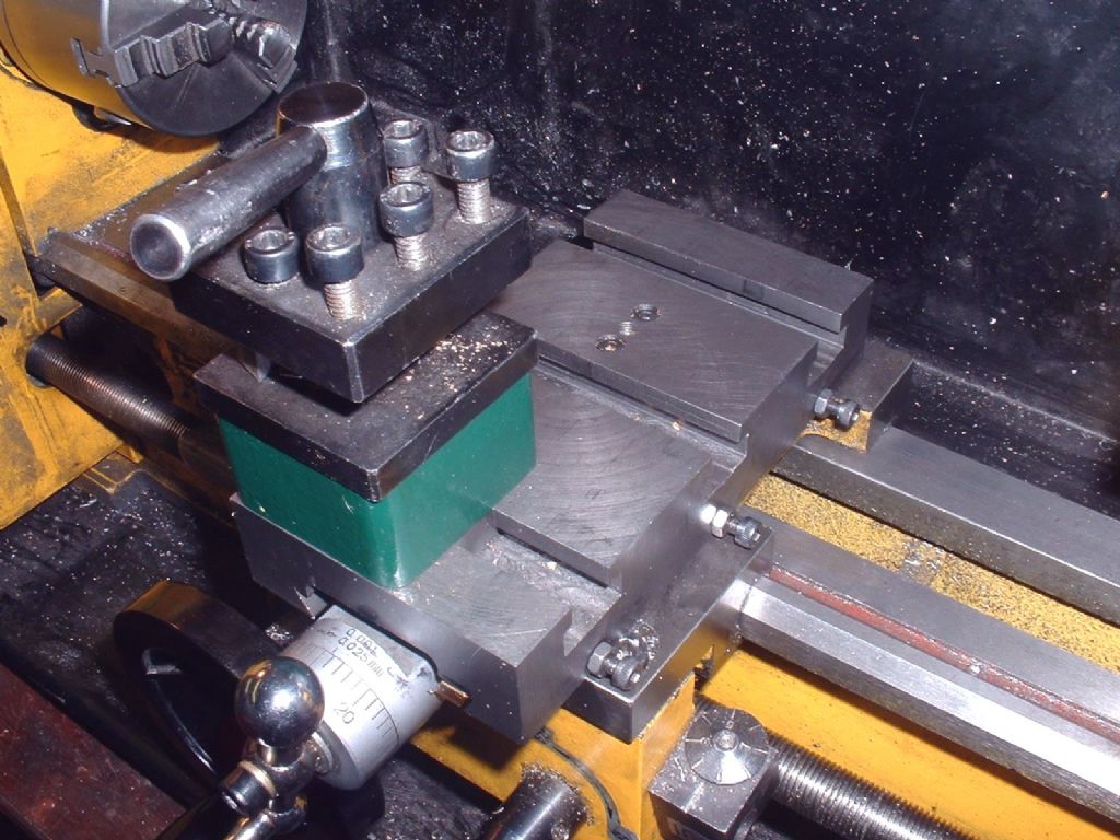 Neil |
Please login to post a reply.
Magazine Locator
Want the latest issue of Model Engineer or Model Engineers' Workshop? Use our magazine locator links to find your nearest stockist!
Sign up to our Newsletter
Sign up to our newsletter and get a free digital issue.
You can unsubscribe at anytime. View our privacy policy at www.mortons.co.uk/privacy
Latest Forum Posts
- *Oct 2023: FORUM MIGRATION TIMELINE*
05/10/2023 07:57:11 - Making ER11 collet chuck
05/10/2023 07:56:24 - What did you do today? 2023
05/10/2023 07:25:01 - Orrery
05/10/2023 06:00:41 - Wera hand-tools
05/10/2023 05:47:07 - New member
05/10/2023 04:40:11 - Problems with external pot on at1 vfd
05/10/2023 00:06:32 - Drain plug
04/10/2023 23:36:17 - digi phase converter for 10 machines.....
04/10/2023 23:13:48 - Winter Storage Of Locomotives
04/10/2023 21:02:11 - More Latest Posts...
- View All Topics
Support Our Partners


Shopping Partners
Subscription Offer

Latest "For Sale" Ads
- Reeves** - Rebuilt Royal Scot by Martin Evans
by John Broughton
£300.00 - BRITANNIA 5" GAUGE James Perrier
by Jon Seabright 1
£2,500.00 - Drill Grinder - for restoration
by Nigel Graham 2
£0.00 - WARCO WM18 MILLING MACHINE
by Alex Chudley
£1,200.00 - MYFORD SUPER 7 LATHE
by Alex Chudley
£2,000.00 - More "For Sale" Ads...
Latest "Wanted" Ads
- D1-3 backplate
by Michael Horley
Price Not Specified - fixed steady for a Colchester bantam mark1 800
by George Jervis
Price Not Specified - lbsc pansy
by JACK SIDEBOTHAM
Price Not Specified - Pratt Burnerd multifit chuck key.
by Tim Riome
Price Not Specified - BANDSAW BLADE WELDER
by HUGH
Price Not Specified - More "Wanted" Ads...
Get In Touch!
Do you want to contact the Model Engineer and Model Engineers' Workshop team?
You can contact us by phone, mail or email about the magazines including becoming a contributor, submitting reader's letters or making queries about articles. You can also get in touch about this website, advertising or other general issues.
Click THIS LINK for full contact details.
For subscription issues please see THIS LINK.
Digital Back Issues


Donate

 Register
 Log-in
Model Engineer Magazine
- Percival Marshall
- M.E. History
- LittleLEC
- M.E. Clock

ME Workshop
- An Adcock
- & Shipley
- Horizontal
- Mill

Subscribe Now
- Great savings
- Delivered to your door

Pre-order your copy!
- Delivered to your doorstep!
- Free UK delivery!
All Forum Topics > Manual machine tools > Alignment of lead screw on CL300