
stuart s50 build
| matt | 03/12/2009 11:45:48 |
| 24 forum posts | hi all
Im building a stuart s50 mill engine, with help from the tubal cain articles. I've got to the stage where I need to machine the cylinder and hit a brick wall. Does anyone have any experience/pictures of how to mount the casting in the four jaw to do the initial facing on the ends and the main bore. I think once the bore is done it should be simple enough but I cant work out how to grip it satisfactorily to get to that stage. The article just says mount in 4 jaw and true up to outer diameter, but the photo doesnt really give a clue how its set up. problem is the rim at either end of casting is larger than the center section, this means the 4 jaw is only really gripping on a small section of casting and rest is unsupported.
any suggestions appreciated
Matt |
| JasonB | 03/12/2009 13:09:40 |
 25215 forum posts 3105 photos 1 articles | Smal lpieces of aluminium between the jaws and the 3 sides of the cylinder will allow you to hold it with the 4th jaw on the valve face. Just make sure there is no risk of the packers flying out. If th edifference is not that much then you may be able to bend a bit of flat into a "U" shape.
You may find a bung of wood in the end of the cyl will help with marking the ctr so you can align it with the tailstock ctr and a square off the chuck face to keep it in line
Try to machine the bore and the end of the casting where the piston rod enters at the same setting then all will be square and concentric, it does not matter if the other end is a little off.
Jason |
| matt | 03/12/2009 17:48:20 |
| 24 forum posts | worked a treat. had to use individual bits of aluminium for 3 faces but have got first end faced of square to valve face. can now use that to setup other end for facing and will do bore at same setup.
matt |
| Doddy | 02/01/2010 18:17:09 |
 72 forum posts 103 photos | As a novice I'm currently having a go at building a Stuart 10H and also the Score, had a similar problem of how to bore the crosshead guide in the sole plate. How to keep the bore parallel to the base, square to the bearing mounts and on centre whilst holding it firmly?
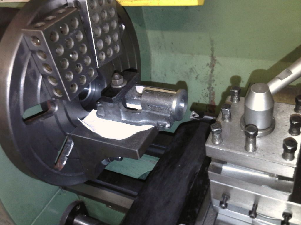
The casing core is 1/2" so I removed the flash with a 1/2 reamer then mounted it on my face plate, square using a reamer in the tail stock got me within a few thou very quickly, with the a parallel reamer in the bore check along the shank with a DTI is easy
BTW the threaded square blocks were just handy for balance wieghts but are great for mounting smaller cylinder blocks
Using a 1/2" reamer to locate parallel, centre and square in one go on the "Score"
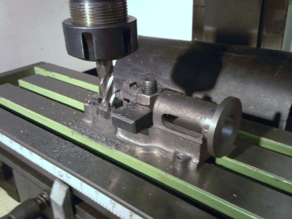 milling bearing mount tops on the 10H
Edited By David Dodwell on 02/01/2010 18:25:18 |
| Circlip | 02/01/2010 19:21:49 |
| 1723 forum posts | Already been shown Matt, but not only the angle plate fastened to the faceplate but also a "Keats" type vee block to faceplate. Regards Ian. |
| JasonB | 02/01/2010 19:39:39 |
25215 forum posts 3105 photos 1 articles | I'd be a little weary of using a reamer to remove casting flash, it soften chilled and you may get a bit of sand left on the cast surface which won't do your reamer much good. Maybe open up with a 1/2" drill then use a bit of 1/2" bar to set it up.
Jason |
| mgj | 02/01/2010 20:38:58 |
| 1017 forum posts 14 photos | Also, just drilling doesn't guarantee that the bores are parallel, because the drill will follow the hole. And so will a reamer. Wiser to bore first with a single point boring tool. You have a mill - why not just mount up on a right angle plate, skim off the mounting flange, rough bore and then finish drill and ream. (or fine bore and ream.) 2 holes parallel, the right distance apart, and a datum square face all built in at one setting. Or for lathe only owners, just set up on the vertical slide, which is the way I did a Stuart Launch. Same end result. Simplifies setting up later. Edited By meyrick griffith-jones on 02/01/2010 20:39:50 |
| mgj | 02/01/2010 21:34:36 |
| 1017 forum posts 14 photos | Actually, one shouldn't take more than about .005" on diameter with a reamer if you want a decent result, so one should bore (if you want a straight hole) to within a few thou of finished diameter, before reaming - loadsa coolant, and very low speed. And, if you are serious about reaming to size and getting a round hole (which most of us are not) then you ought really to use a floating reamer holder. |
| Ian S C | 02/01/2010 23:36:11 |
 7468 forum posts 230 photos | meyrick,what is the casting made of,I agree with the lots of coolant if its bronze,but if its cast iron I'd tend to cut it dry.I wouldn't go near it with a reamer untill its bored out to a few thou under size,even then I rarely use a reamer('cos I haven't got many reamers).Ian S C |
| mgj | 03/01/2010 01:21:45 |
| 1017 forum posts 14 photos | I always use coolant on iron, because it gives a better finish, and it controls expansion and it clears chips. (Also it keeps the dust down and stops it going all over the bedways.) I know a lot of people cut iron dry - I have heard of coolant causing a hardening action with iron, but I doubt that's a problem with modern high speed tools. Whichever works best? Edited By meyrick griffith-jones on 03/01/2010 01:22:39 |
| Doddy | 03/01/2010 01:26:59 |
72 forum posts 103 photos | sorry for not explaining myself very clearly - the use of the reamer was just to help set up the rough casting first before boring, not to ream the hole to size! dimensional accuracy is less important than geometrical accuracy for the first cut - the success of these little engines depends up on the centre line of the bore been machined parallel to the base, and square to the bearing journals (square to the crankshaft)
I just found it easier and quicker to set up on the faceplate this way - having spent sometime trying to average out the clock readings from around to outside of the rough castings and getting no where fast I tried a differant way which worked for me - once things are set up geometrically and the first cut is made, I find the dimenisonal accuracy follows easy
Could of used a piece of wood dowel - but the reamer was to hand and fitted the hole nicely in the casting and also the tailstock giving reasonable geometric set up enabling me to clamp to the face plate before boring.
Thought about using my milling maching but it seems not to have the rigidity
sorry if the pictures are a bit misleading - guess it does look like I'm reaming the holes out but this was done by hand with only a light cut as I've found the Stuart casings to be great to work with Edited By David Dodwell on 03/01/2010 01:28:28 |
| Ian S C | 03/01/2010 05:46:32 |
7468 forum posts 230 photos | David I assumed that that was the case,but because of the chance of damage to the cutting edges,I would sugest that the reamer stay in its box until actually being used.Mayrick I'v got a couple of pistons to make from cast iron so I might try one wet and one dry.Ian S C |
| JasonB | 03/01/2010 07:56:02 |
25215 forum posts 3105 photos 1 articles | "The casing core is 1/2" so I removed the flash with a 1/2 reamer"
Just read like you used the reamer to clean up the cast bore??
The way that stuarts cast their parts this method of alignment is just acceptable but I would not want to use it with a sand casting where the core may have moved or may not even be anywher near round
May have been easier to set the casting up with the angle plate stood on your marking out table so it could be checked with squares and height guage. Then plug the bore to make locating the ctr easier and just move the angle plate about on the faceplate until it clocks true
Jason Edited By JasonB on 03/01/2010 08:02:11 |
| Doddy | 03/01/2010 08:59:25 |
72 forum posts 103 photos | many thanks jason will try that |
| mgj | 03/01/2010 13:03:13 |
| 1017 forum posts 14 photos | Ian I just find it a lot easier to collect up one lump of heavy sludge, rather htan chase chippings all over the machine. David - I'm surprised that mill in the picture isn't rigid enough. Unless its a round column and all the vertical movement required is outside the range of the quill. There are a number of good reasons to do it on the mill/cross slide. First of course you get a datum across the front using the easily accessible cylinder mounting flanges. Also of course you get another datum - the bed of the mounting plate. That's parallel to the bores too - automatically. And there is no resetting between bores, other than moving the handwheels. And of course with no second set up, its a lot quicker - without mucking about with angle plates and balance weights. I;m sure that Tubal Cains "how to guide" will have been extremely good. His stuff always was amongst the best IMO. But I doubt that, when he was writing, the average modeller had access to decent sized mills, in the way that many of us do now. Yes, of course the faceplate system will work, and with care will work well, despite "2 set-ups", but not trying to line up off a reamer - used turn and turn about in independent and independently lumpy bores. Much wiser IMO, to have used a square off the faceplate and used the same face or edge on the bedplate as a datum for each set up. To me, the easiest way to have done the job would have been as follows. 1. M/c the bottom of the bedplate. just skim flat. 2. Set up on a angle plate and done front flanges and bores all at the same setting. If you have a DRO I'd have done the flange bolt holes too. 3. Clamped the bed plate, using the flanges as a datum for square and length, and run a cutter across to do the main bearing channels, - set to depth and height. 4. At the same setting, drilled the bearing stud holes. 5. Finally, if I had no DRO, I'd have machined a spigot, popped it in the bores in turn and done the flange bolt holes on a direct indexer . 6. Then using the spigot, set a 4 jaw to ensure concentricity, I'd have machined the cylinder cover locating spigot on the flange. If its a counterbore, even easier - put it in with a slot drill of the right side plunge cutting at stage2. Gawd - can you imagine, setting up an angle plate on the face plate, tapping all to get ti in the right place, and at right angles to a notional diamenter line, so you can slide the bed sideways and still maintain height accurately. Then you have to clamp the bed to the plate and get it square, and slide it sideways and do it again for the second bore . Whichever way you choose, I hope it comes out right. |
| Doddy | 03/01/2010 16:12:37 |
72 forum posts 103 photos | Again many thanks - your experiance show through - I'm finding (as a novice) that one of the enjoyable parts of model engineering is the "think through of how to do something" but it is also the hardest, to get right, without much experiance I'm trying to build up confidence to multi-task each process with the minimum of effort and learn how to trust my machines.
I'm only guessing but you appear to be able to think through these process very easily and in a logical manner in your head - is that through many years in a process / batch / production background or just many years model making ?
I was a maintenance craftsman many years ago and I'm enjoying through this hobby the re-discovery of my lost fitting skills - but as we became "parts replacement engineers" over the years, it appears I've lost the skill (or trust in my skills) to think the job right through in one go !
This is only my second project in model making and I'm enjoying the re-discovery of that old saying - "there's more than one way to skin a cat"
|
| mgj | 03/01/2010 16:51:29 |
| 1017 forum posts 14 photos | Agreed David - there is always more than one way...., and nor even is any way "best". I think you have hit the nail on the head when you say -think the problem through, and add to that "Where is my datum - if possible I only want one", so I don't end up breaking down or making set ups unnecessarily. And, you must trust your machines instruments and dial settings, as long as you deal with the backlash. People get very het up about dimensions and drawings, but if you can visualise the finished bit, and just over a cup of coffee, work out how you are going to achieve each dimension/parallel etc, it will come. Simply because you can see then that A depends on B and B&C must be true or parallel or vertical or whatever. Then it becomes quite easy to see what has to be done first and so forth. And also how to hold hte job for each phase, because what one doesn't want to do is find out that you are holding it by a face or place you need to machine! 2nd project - well it seems to be coming on fine. Be careful when you do that crank - its terribly spindly, and very easy to bend into spaghetti. The Stuart Launch one is much the same, and I could tell you the price of a replacement 20 years ago.  No I was never in production/process personally. I was in DQA for a while, and did a lot on trials and R&D on tanks. |
| Nigel McBurney 1 | 12/01/2010 22:54:17 |
 1101 forum posts 3 photos | Hi there are lots of ways to do any job,but on model engineering size equipment and very often on full size m/cs as well ,invariably the best results in boring castings are obtained by rotating the work with stationary tools provided the work is balanced,also I have read in the above posts and in ME recently the use of soluble oil on cast iron, recomended practice since engineering began is to cut dry,the carbon/graphite in the iron acts as a lubricant,if you find that the life of the tool is improved by coolant then you are cutting the material too fast ,80 ft per minute surface is correct,in over 50 years in the business I have only seen cast iron machined using soluble once and this was on a very high tech fully automatic machining line ,totally computer controlled to machine a range of castings,and when asked why use soluble the answer was swarf removal,it was the only way they found at the time to get rid of the swarf as there were no operators involved in the operations. Cast iron swarf mixed with soluble will rust solid very quickly,ok you may keep the machine clean but it will get under the lathe saddle and other inaccesable places. .when I was apprenticed most of our work on centre lathes was cast iron or non ferrous and none of them were fitted with soluble pumps,this was deliberate ,so there was no mixing of swarf and soluble. I f problems occur when reaming cast iron then tallow was applied to the reamer. |

Please login to post a reply.
Want the latest issue of Model Engineer or Model Engineers' Workshop? Use our magazine locator links to find your nearest stockist!
Sign up to our newsletter and get a free digital issue.
You can unsubscribe at anytime. View our privacy policy at www.mortons.co.uk/privacy
- hemingway ball turner
04/07/2025 14:40:26 - *Oct 2023: FORUM MIGRATION TIMELINE*
05/10/2023 07:57:11 - Making ER11 collet chuck
05/10/2023 07:56:24 - What did you do today? 2023
05/10/2023 07:25:01 - Orrery
05/10/2023 06:00:41 - Wera hand-tools
05/10/2023 05:47:07 - New member
05/10/2023 04:40:11 - Problems with external pot on at1 vfd
05/10/2023 00:06:32 - Drain plug
04/10/2023 23:36:17 - digi phase converter for 10 machines.....
04/10/2023 23:13:48 - More Latest Posts...
- View All Topics


- Reeves** - Rebuilt Royal Scot by Martin Evans
by John Broughton
£300.00 - BRITANNIA 5" GAUGE James Perrier
by Jon Seabright 1
£2,500.00 - Drill Grinder - for restoration
by Nigel Graham 2
£0.00 - WARCO WM18 MILLING MACHINE
by Alex Chudley
£1,200.00 - MYFORD SUPER 7 LATHE
by Alex Chudley
£2,000.00 - More "For Sale" Ads...
- D1-3 backplate
by Michael Horley
Price Not Specified - fixed steady for a Colchester bantam mark1 800
by George Jervis
Price Not Specified - lbsc pansy
by JACK SIDEBOTHAM
Price Not Specified - Pratt Burnerd multifit chuck key.
by Tim Riome
Price Not Specified - BANDSAW BLADE WELDER
by HUGH
Price Not Specified - More "Wanted" Ads...
Do you want to contact the Model Engineer and Model Engineers' Workshop team?
You can contact us by phone, mail or email about the magazines including becoming a contributor, submitting reader's letters or making queries about articles. You can also get in touch about this website, advertising or other general issues.
Click THIS LINK for full contact details.
For subscription issues please see THIS LINK.


 Register
 Log-in
Model Engineer Magazine
- Percival Marshall
- M.E. History
- LittleLEC
- M.E. Clock

ME Workshop
- An Adcock
- & Shipley
- Horizontal
- Mill

Subscribe Now
- Great savings
- Delivered to your door

Pre-order your copy!
- Delivered to your doorstep!
- Free UK delivery!