Forum sponsored by:

Cutting Small Internal Keyways
| Chris Crew | 03/10/2023 00:21:26 |
 418 forum posts 15 photos | I am building a device that requires a 0.625" diameter sleeve, bored 0.375", to have both an internal and external keyway 0.0625" x 0.125". The external keyway is not an issue but having spent an evening in the workshop making a slotting tool for the Radford slotting attachment (it works the same as any number of slotting attachment designs that have been published for the Myford), I have had very limited success in forming the keyway which is not to the standard I would have hoped for (probably another addition to the scrap box). The problem is that the tool shank is very slender 0.375", which fills the whole of the bore the idea being that this would prevent deflection and the cutting bit was of 0.125" HSS set across the diameter to be nudged out a few thou. at a time until the full depth of the key way was reached. The problem arose when the 0.125" HSS cutter kept breaking under the force applied by the slotting tool. After a couple of attempts I tried again with a tool similar to a boring tool which worked up to a point but was mostly deflected out of the slot towards the end of the cut resulting in a keyway of tapering depth. I removed this taper with the edge of a small file but I am not very happy with the result. So, can anyone suggest a method for obtaining a better result that they may have used themselves? I know the Radford slotter works well enough on larger sizes when the tool can be made big enough to resist deflection because I have squared holes, cut internal splines and keyways with it but not at such a small size. I am thinking that the professionals may use some form of broaching to form keyways inside small diameter bores, e.g. the Myford lead-screw spacer, but I don't have this facility. Edited By Chris Crew on 03/10/2023 00:22:45 |
| Diogenes | 03/10/2023 06:38:13 |
| 61 forum posts 6 photos | If I had to do it I'd make the blade narrower and nibble, stepping it over to reach full width, I'd probably go for something say third to half full width. I've done this on slightly larger slots - tedious, agreed, but not as tedious as failing to achieve a slot at all. Edit; don't use a shank that fills the bore, leave a bit of 'give' for inevitable deflection of the tool, could be that jam ups & breakages are due to this. Start with the bit 'choked down' in the shank and extend it to enable cutting to full depth - you might even need to make another bit to tidy up, or even achieve full depth.. Edited By Diogenes on 03/10/2023 06:45:01 Edited By Diogenes on 03/10/2023 06:49:14 |
| JasonB | 03/10/2023 06:52:49 |
 25215 forum posts 3105 photos 1 articles | I've always had good resuls doing it by "hand" using the lathe carriage or mill's quill to feed the tool though now I mostly use cheapish broaches. Your advance a couple of thou may be the problem I find 1 thou is the most I advance the tool by somethimes less, it's a case of lots of very fine cuts which won't deflect the tool as much as larger ones will My usual tool is a boring bar type that holds an HSS tool at right angles that is ground like a zero top rake parting tool. Shank has always been smaller than the bore when using this type of tool so the cut can be put on. J PS how long is the slot? |
| DC31k | 03/10/2023 07:55:08 |
| 1186 forum posts 11 photos | A couple of observations: While the advice is not to fill the bore with the shank, maybe sliding contact between the shank and the bore on the opposite side to the keyway would be beneficial as then the component will help support the slotting bar in the same way as a broach bush. This does presume 'on tool' adjustment of cutting depth. Jason asks how long is the slot. By convention, we make slots the same length as the component they are in, but you could see if this is a necessary feature of your design. If the slot does not need to be full length, remove those parts that do not need to be there by plunging vertically with an endmill. If you plug the bore (or on a piece of stock where the bore is not already formed), you could drill away a small part of the keyway leaving less for the slotting tool to remove. Is it worth trying to 'pull broach' rather than 'push broach'? Change the keyway to the shaft and use a couple of dog point grub screws to form the 'key'. |
| Martin Connelly | 03/10/2023 07:57:52 |
 2549 forum posts 235 photos | Any chance of fitting a plug then using a 2mm or 0.04" drill through to take out the bulk of the material first, as Jason pointed out you did not state how long the bush is. I have done long keyways on the lathe as Jason suggests but it took a lot of passes at each setting to clear out the slot. The problem is that for long slots a tool with too much rake digs in and overcuts but a tool with too little rake deflects the tool enough to skip over the surface after a short section of cutting. Another method is to make a bush as is used with broaching cutters and then make your own cutter from HSS. I think I have a 3mm broach but I would have to make a suitable bush for this bore but I think a home made one to suit your inch sizes may be possible. Martin C |
| Chris Crew | 03/10/2023 08:04:20 |
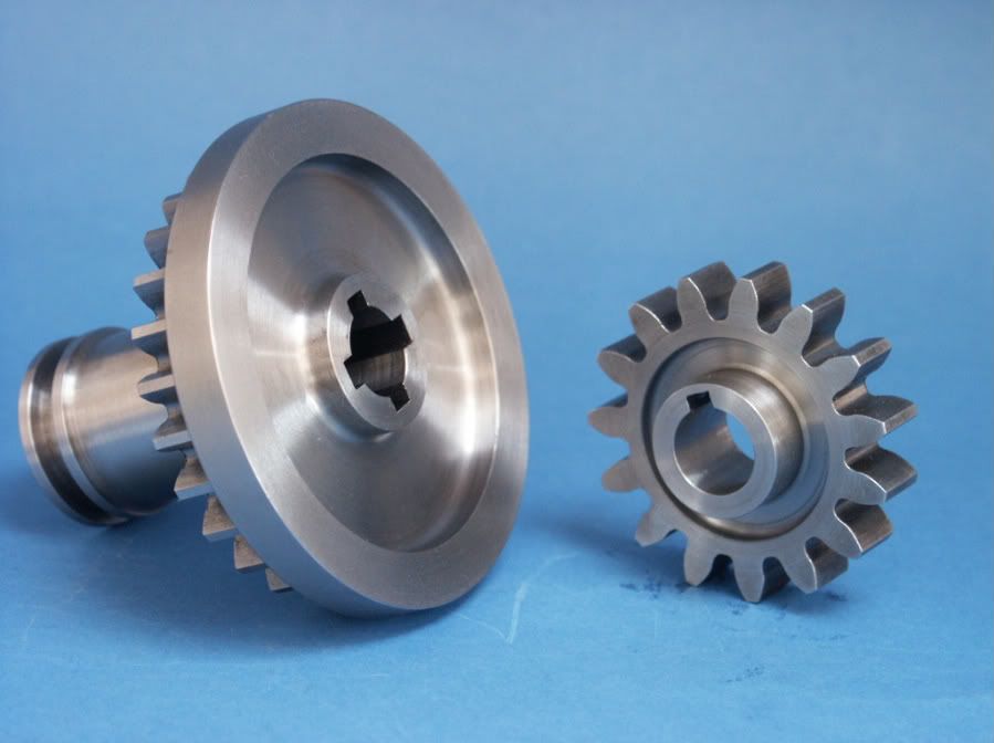
418 forum posts 15 photos | "PS how long is the slot?" The sleeve is as long as two Myford change gears mounted side-by-side, so about 1". The component to be made is identical to a change-gear bush but needs to be internally keyed to drive a 0.375" shaft. The device I am making is the Parkes' gear hob backing-off device, published in MEW No.57, and I have thus far followed the drawings. I have considered altering and simplifying the design because the UJ's connected with the drive shaft do not appear to be very robust and look smaller than those showing in the photographs in the magazine but it's difficult to tell. I know the device works because the late Dr. Parkes was demonstrating it at an exhibition several years ago and, following the interest I was showing in the device, he very kindly sent me a copy of the drawings and the accompanying script from which I have been working. I only very recently tracked down a copy of the magazine that it appeared in. I have had an overnight brainwave as to a possible solution to the problem but I will not reveal my idea until I have been in the workshop today to prove it one way or another. If it works I will describe it in this post and if it doesn't I will just keep trying. PS. Many thanks for the suggestions thus far. I will try them all if my 'brainwave' fails. Edited By Chris Crew on 03/10/2023 08:11:54 |
| DMB | 03/10/2023 08:48:40 |
| 1585 forum posts 1 photos | JasonB s remark, " so the cut can be put on." Lightbulb lit up at last! You need to have a cutter shank just a bit smaller than the bore to allow the cross slide to put on another incremental cut, really, really, small increment. I get the impression that Chris is going full depth from the start, no wonder busted tool! Another point is, even with bigger slots where the operator thinks he can get away with bigger cuts, is the extreme load placed upon the working components of the saddle. Slotting is a rather brutal method of metal butchery, requiring considerable effort. Think of the tiny incrementally sized teeth on a broach. Care and patience! John |
| John Hinkley | 03/10/2023 08:53:35 |
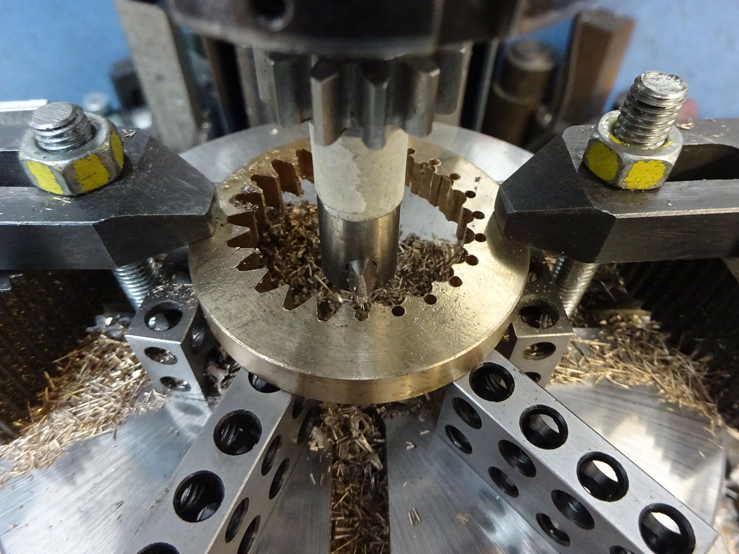
 1545 forum posts 484 photos | Chris, Faced with a similar problem when I was building my original gearbox, I used a broach and home made broach bush. The first internal keyway was made in the normal manner and then the bush was rotated so that the formed keyway located in a second slot in the bush machined at the desired angular displacement from the first. The benefit of using a broach, of course, is that you get an even depth cut throughout the whole length of the workpiece. Downside is, they're blooming expensive! I can't take a photo of it without stripping the model down, but here's a screenshot of the CAD file of the broach bush:
In this instance it was to produce 6 equi-spaced keyways so each rotation was at 60° to the previous one. I'm doing a similar thing for my latest gearbox, but that's all 3D printed so is just a matter of pressing a button a waiting a short while. John
Edited By John Hinkley on 03/10/2023 09:15:27 |
| Nigel Graham 2 | 03/10/2023 08:57:10 |
| 3293 forum posts 112 photos | This being a potential question for my own project, I looked at using the shaper - manually-operated in my case. The text-books for that indicated internal shaping is by drawing the tool through the work, with the clapper-box locked. The latter point is emulated by using the lathe as a shaper by winding the saddle back and forth (not recommended for frequent use). Though not explained, I think this is to avoid digging-in, as the spring of the tool-bar will tend to lift it. The top-rake should be low to minimise the risk further. . The tool-bar is best not contacting the bore, as you don't want to risk scoring or wearing that. and anyway if made the same diameter would require either the flanks cutting back to allow down-feeding, or setting the feed by adjusting the tool-bit itself. The area ahead of the cutting edge needs enough relief to accommodate the shaving. If needed, you can relieve the tool on both the shaper and lathe by using the appropriate feed-screw. (For short, one-off operations such relieving might not be necessary anyway.) ' To support a drill or slot-drill removing the bulk of the slot material, plug the bore with a piece of the same material. . I don't know the gear-hobbing machine you describe so I don't know what are specified for the universal joints, but neat ball-type joints are commercially available, that would very likely handle the loads on this machine. I have set two aside for the feed-drive on a small horizontal mill I am slowly re-commissioning. |
| JasonB | 03/10/2023 09:00:05 |
25215 forum posts 3105 photos 1 articles | No Chris said "a couple of thou" no full depth. You can make tools that have a shank that fits the bore and a long tool that is pushed out by a grub screw to advance it but at 3/8" it is getting a bit tight to fit it all in. So by having say an 8mm or 5/16" shank and the tool sticking out almost all the remaining 1/16" you can put on a cut . 1/8" slot in a 3/8" bore is a bit wider than standard which is generally 1/4" the shaft/hole size so 3/32 would be usual for 3/8. Also 1" is getting a bit on the long side, I don't think standard broach bushes are that long but woul dneed to measure mine though I do make my own longer ones. I have done 1" long is steel @ 3/16" wide but probably used about a 5/8" shank tool into a 3/4" bore but it is a lot of work and needs many passes including regular spring passes, the one on the left.
|
| bernard towers | 03/10/2023 09:23:09 |
| 1221 forum posts 161 photos | Chris how about two pieces of tube, one is 1/2 od x 3/8 I’d and one 5/8 od x 1/2 I’d. Slot both with an 1/8 cutter, slide one inside the other and silver carefully together. Before you silver them you can also set the spacing of the slots/ key ways. |
| Brian Wood | 03/10/2023 09:59:51 |
| 2742 forum posts 39 photos | I was about to make the same suggestion myself, with the addition of inserting a filler of carbon in the internal slot to prevent silver solder from wicking in Brian |
| Nigel Graham 2 | 03/10/2023 10:35:59 |
| 3293 forum posts 112 photos | I have known of, but not tried, using that insert method for splines. Jason - If the bar is drilled at an angle, say 45º, and the grub-screw enters from the end, you lose the adjustment by screw but gain extra clamping area with less protrusion above the bar. It may need an angled slug between the screw and tool for better clamping. You'd need some other way to measure the feed, but if the assembly will fit the bore before cutting, that can be applied by the lathe's cross-feed or the shaper's down-feed anyway.
|
| bernard towers | 03/10/2023 10:47:43 |
| 1221 forum posts 161 photos |
Edited By bernard towers on 03/10/2023 10:49:18 |
| bernard towers | 03/10/2023 10:51:08 |
| 1221 forum posts 161 photos | As per usual photos in wrong order and text moved all over the place and when you go into edit the text is in a completely different place, roll on the new edition |
| JasonB | 03/10/2023 11:04:50 |
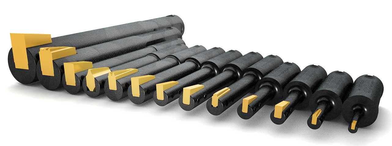
25215 forum posts 3105 photos 1 articles | Nigel this is the adjustable sort I was talking of where the long cutting tool pivots and can be pushed out by a grub screw. I just use a smaller dia shank and an HSS bit at right angles
Very similar concept to what a modern CNC machine will use just moving thetool up and down while slowly advancing the work
Or you can just mount a bit of square HSS in the toolpost and use that if metal is softer or length shorter
|
| peak4 | 03/10/2023 11:50:09 |
 2207 forum posts 210 photos | Chris, you mention a slotting tool in the style of a boring bar, which is what I've used in the past for similar jobs. Edited By peak4 on 03/10/2023 11:52:08 |
| Baron J | 03/10/2023 11:59:44 |
| 4 forum posts | Hi Chris, For whatever reason I don't seem able to get at my albums ! In them there is a picture of a tool I made to do exactly the job you are doing !
Edited By Baron J on 03/10/2023 12:00:12 Edited By Baron J on 03/10/2023 12:00:40 |
| Chris Crew | 03/10/2023 13:58:13 |
418 forum posts 15 photos | Well, I tried one of my brainwaves this morning and met with limited success, so limited in fact that I am going to declare it a failure but I did manage to cut a half acceptable keyway in a cam blank but this is only about the width of a Myford change gear and even then I had to take out a taper in the slot, where the tool had deflected, with the edge of a small file again. I have another idea that will require a bit of silver soldering but that's for another day. I also had the same idea as Bernard Towers about inserting a slotted inner sleeve into the bored out bush so I may try that too. If I try all the suggestions I am sure I will eventually hit on something that works for me and then stick with it because I would eventually like to make a few replicas of Myford change gears which obviously require an internal keyway in the blank. BTW, some excellent work shown in the photographs, well done! (I can only dream of achieving such standards). |
| Andrew Johnston | 03/10/2023 14:45:34 |
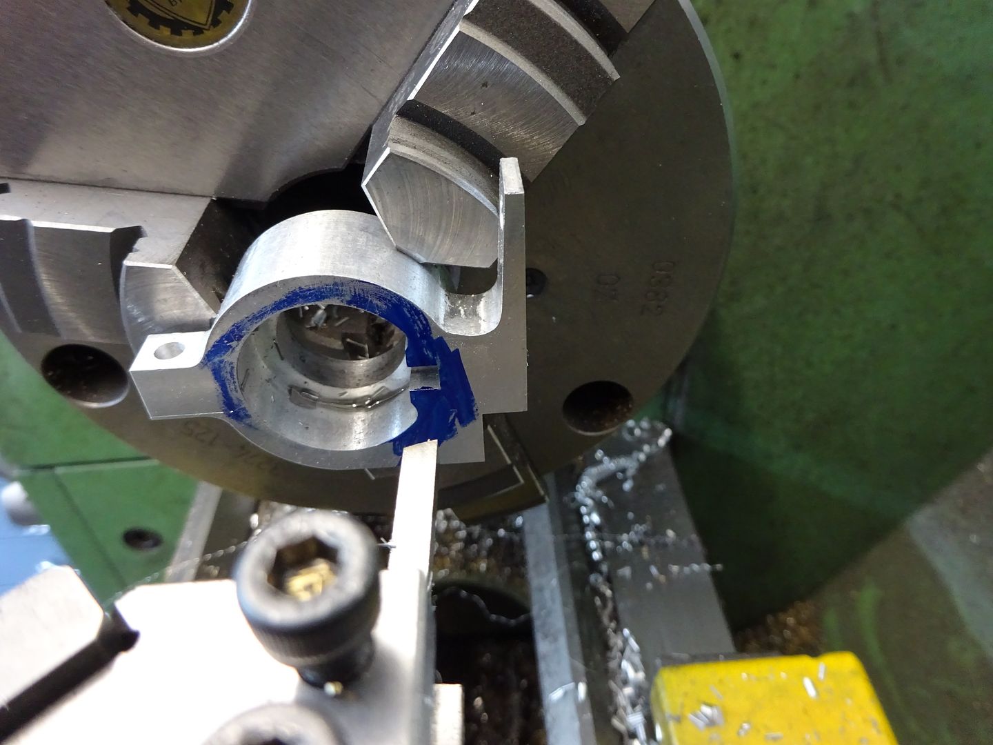
 7061 forum posts 719 photos | Personally I'd use a broach and arbor press. But I have cut a 1/8" wide keyway, in steel, in a 1/2" diameter hole over a length of 1-3/4" by slotting:
I used a slotting head on the Bridgeport but that is no different to using the saddle on a lathe, just a bit quicker. The trick is to add top rake to the toolbit so that it doesn't push outwards and ideally has a slight tendency to pull in. Andrew |


Please login to post a reply.
Magazine Locator
Want the latest issue of Model Engineer or Model Engineers' Workshop? Use our magazine locator links to find your nearest stockist!
Sign up to our Newsletter
Sign up to our newsletter and get a free digital issue.
You can unsubscribe at anytime. View our privacy policy at www.mortons.co.uk/privacy
Latest Forum Posts
- *Oct 2023: FORUM MIGRATION TIMELINE*
05/10/2023 07:57:11 - Making ER11 collet chuck
05/10/2023 07:56:24 - What did you do today? 2023
05/10/2023 07:25:01 - Orrery
05/10/2023 06:00:41 - Wera hand-tools
05/10/2023 05:47:07 - New member
05/10/2023 04:40:11 - Problems with external pot on at1 vfd
05/10/2023 00:06:32 - Drain plug
04/10/2023 23:36:17 - digi phase converter for 10 machines.....
04/10/2023 23:13:48 - Winter Storage Of Locomotives
04/10/2023 21:02:11 - More Latest Posts...
- View All Topics
Support Our Partners


Shopping Partners
Subscription Offer

Latest "For Sale" Ads
- Reeves** - Rebuilt Royal Scot by Martin Evans
by John Broughton
£300.00 - BRITANNIA 5" GAUGE James Perrier
by Jon Seabright 1
£2,500.00 - Drill Grinder - for restoration
by Nigel Graham 2
£0.00 - WARCO WM18 MILLING MACHINE
by Alex Chudley
£1,200.00 - MYFORD SUPER 7 LATHE
by Alex Chudley
£2,000.00 - More "For Sale" Ads...
Latest "Wanted" Ads
- D1-3 backplate
by Michael Horley
Price Not Specified - fixed steady for a Colchester bantam mark1 800
by George Jervis
Price Not Specified - lbsc pansy
by JACK SIDEBOTHAM
Price Not Specified - Pratt Burnerd multifit chuck key.
by Tim Riome
Price Not Specified - BANDSAW BLADE WELDER
by HUGH
Price Not Specified - More "Wanted" Ads...
Get In Touch!
Do you want to contact the Model Engineer and Model Engineers' Workshop team?
You can contact us by phone, mail or email about the magazines including becoming a contributor, submitting reader's letters or making queries about articles. You can also get in touch about this website, advertising or other general issues.
Click THIS LINK for full contact details.
For subscription issues please see THIS LINK.
Digital Back Issues


Donate

 Register
 Log-in
Model Engineer Magazine
- Percival Marshall
- M.E. History
- LittleLEC
- M.E. Clock

ME Workshop
- An Adcock
- & Shipley
- Horizontal
- Mill

Subscribe Now
- Great savings
- Delivered to your door

Pre-order your copy!
- Delivered to your doorstep!
- Free UK delivery!
All Forum Topics > Help and Assistance! (Offered or Wanted) > Cutting Small Internal Keyways