Forum sponsored by:

Making a Unimat 3 pulley ... On a Unimat 3
| Julius Henry Marx | 23/06/2023 02:11:05 |
| 113 forum posts 52 photos | Hello: Now that my Unimat 3 is behaving much better, I am undertaking pending tasks, one of them being a replacement for the OEM plastic drive pulley with an aluminium one. I am practically finished with it, with disk on dimension and only the grooves left to turn. I have made a copy of the original but with a couple of differences: I left some material on the ouside face of the pulley for future use. One possibility is to make another (smaller) groove to use if you flip it around and and another is to have where to put something like disk for a Hall sensor. The thing is that at this point I am at odds on how to go about making the grooves ie: what tool to use given the small space to work in even when using the small OEM tool holder. This is the only arrangement I could come up with with the tools I have but I don't like it too much as it would have to be finished by hand with a round file.
I'd appreciate an opinion on this. Thanks in advance. Best, JHM |
| JasonB | 23/06/2023 07:13:17 |
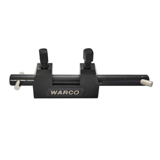
 25215 forum posts 3105 photos 1 articles | Take a piece of 6mm square steel and drill a 3mm hole across it say 5mm from the end. Drill and tap a second hole M3 in from the end to meet the hole. You can now grind a piece of 3mm HSS (old ctr drill) as a cutting tool that can be held in your ned tool holder. I suggest you work out a set of co-ordinates to form the grooves in a series of steps as the lathe will unlikely be upto using a form tool of the required width Like the left hand end of this
|
| Michael Gilligan | 23/06/2023 07:22:49 |
 23121 forum posts 1360 photos | Just a thought … If I was in your place, I would take the opportunity to convert the pulley system to Poly-Vee they are available in small pitch, and turning the grooves is much easier than the job you have in mind ! MichaelG. . Ref. __ **LINK** https://www.acorn-ind.co.uk/power-transmission/industrial-belts/poly-v-ribbed-belts/?odmm=1%2E6 |
| John Olsen | 23/06/2023 07:27:17 |
| 1294 forum posts 108 photos 1 articles | It seems a pity to go to a lot of trouble to make an aluminium pulley which will not really perform any better than the original plastic. Mine used to do tricks like grabbing the belt and wrapping it twice around the small pulley. The round belt is not really up to the job. My solution was to make a toothed belt drive which fitted inside the original cover. It works really well. I did all the work on the Unimat, including milling the teeth. I do have the milling attachment and the simple dividing attachment. The hardest part was that one of the pulleys needed 41 teeth, which can't be done with the dividing attachment, so that was done by wrapping a strip of tenth inch graph paper around the blank and marking out from that. John |
| Kiwi Bloke | 23/06/2023 07:53:30 |
| 912 forum posts 3 photos | If you're using common-or-garden O rings as belts (they're so cheap!), you'll find that they're soft enough to work pretty well in V grooves - possibly better than in arcuate-section grooves. The other suggestions of poly-vee or toothed belts are certainl better, but more $$ & more work... Just a thought: O rings won't transmit as much torque as you might sometimes like. I've never seen it suggested, in this application, but running more than one belt, on multi-groove pulleys would multiply the torque transmission, in proportion to the number of belts. It's a standard technique with V-belts, but these aren't particularly stretchy, so they need to be of matched dimensions, so that they share duty pretty evenly. Edited By Kiwi Bloke on 23/06/2023 08:05:24 |
| Circlip | 23/06/2023 11:19:10 |
| 1723 forum posts | Lot to be said for the torque 'limiting' properties of a round belt on a small machine. Regards Ian |
| Julius Henry Marx | 23/06/2023 13:04:53 |
| 113 forum posts 52 photos | Hello: Posted by JasonB on 23/06/2023 07:13:17: ... 6mm square steel and drill a 3mm hole across it say 5mm from the end. Drill and tap a second hole M3 in from the end to meet the hole. You can now grind a piece of 3mm HSS (old ctr drill) as a cutting tool ... Nice ... 8^) I'll see what I have in my odds & ends box. I recall there is a few small/short pieces of round cobalt steel. ... set of co-ordinates to form the grooves in a series of steps as the lathe will unlikely be upto ... Yes, I think this has to be slow and carefully thought out. Thank you for your input. Best, JHM |
| Julius Henry Marx | 23/06/2023 13:14:41 |
| 113 forum posts 52 photos | Hello: Posted by Michael Gilligan on 23/06/2023 07:22:49:
... opportunity to convert the pulley system ... I have given thought to changing the pulley system a few times but the cost of it all has kept me back as there is much tooling I still need to purchase. That and the availability of and low price of reasonably quality belting was a deal breaker. And then there's my own lack of experience to consider: for me (at this moment) a round PU belt that will slip under excess force means saving a tool, an expensive piece of material or some weak part of my U3 which may end up being a hassle to source or manufacture. Thanks for your input. Best, JHM |
| Julius Henry Marx | 23/06/2023 13:22:22 |
| 113 forum posts 52 photos | Hello: Posted by John Olsen on 23/06/2023 07:27:17: ... a lot of trouble to make an aluminium pulley which will not really perform any better ... Not for me, I take it as part of my getting acquainted with the U3 / learning how to use it process and attempt to overcome its limitations. I have a couple of other projects in waiting that will need pulleys more or less of this size so I need the practise. That said, the original pulley slowly turns my green belting black, sure sign of wear in the (ca. 1980) plastic, in surprisingly good condition. I have checked that when stalling/slippage occurs with the new 24V/200W motor, it is at the motor's spindle and not at the plastic pulley, hence my decision to make a new one. ... round belt is not really up to the job. I tend to agree with that but for the time being I'll have to stay with that, it can be a life saver. (see my other post above) ... ... make a toothed belt drive ... Yes, I have looked into that option. One thing that called my attention in a video I saw was that the use of a toothed belt produced a lot of noise compared to the OEM belting. Maybe it was not installed correctly / wrong type of belt? Thanks for your input. Best, JHM Edited By Julius Henry Marx on 23/06/2023 13:31:04 |
| Julius Henry Marx | 23/06/2023 13:44:52 |
| 113 forum posts 52 photos | Hello: Posted by Kiwi Bloke on 23/06/2023 07:53:30: ... common-or-garden O rings as belts ... Availability of quality common 'O' rings locally is very limited in both size and material. And as they are imported, end up being rather expensive for what they are. I really like the idea of being able to make my own belts from PU belting material practically on the fly and as needed. O rings won't transmit as much torque ... Indeed ... But as I have mentioned above, that is a good thing for me at this moment. ... running more than one belt, on multi-groove pulleys ... It is an interesting idea to be considered: economical / easily made round belting with proportionally more torque. Would not be much of an issue space-wise: the belt cover plastic is in bad shape and will have to be replaced with another solution. The trick then will be to make them exactly the same size lest one of them slip. Thank you for your input. Best, JHM Edited By Julius Henry Marx on 23/06/2023 13:57:21 |
| Julius Henry Marx | 23/06/2023 13:48:37 |
| 113 forum posts 52 photos | Hello: Posted by Circlip on 23/06/2023 11:19:10: Lot to be said for the torque 'limiting' properties of a round belt ... Indeed there is: Unimat 3 Beginner's Insurance. 8^° Thanks for your input. Best, JHM |
| Julius Henry Marx | 23/06/2023 20:14:18 |
| 113 forum posts 52 photos | Hello: Posted by JasonB on 23/06/2023 07:13:17: ... piece of 6mm square steel and drill a 3mm hole across it say 5mm from the end. Drill and tap a second hole M3 in from the end to meet the hole. Almost there.
All the carbide bits were ⌀ 3.0mm so I cut a 25mm piece of shank from an old 5mm masonry drill bit in bad shape. Not having suitable stock, made a piece of 7mm x 8mm x 55mm on the four jaw from an uneven piece of steel I had around. The whole thing will fit nicely in the OEM tool holder:
The question now is what form/shape should the bit be to make the groove? Thanks in advance. Best, JHM |
| david bennett 8 | 23/06/2023 22:08:53 |
| 245 forum posts 19 photos | I changed all my pulleys to "V" grooves, taking 4mm fusible watchmakers lathe belting. This transmits enough torque to stall a scooter motor that i've fitted. If you want torque insurance, just make the belt a little longer or flip to a smaller pulley on one side. The groove is simply made with a parting tool to first cut a central groove of the required depth, then cut the angled sides withthe same tool in the compound. (I made the pulley so it could be mounted either way round ) The belt must sit in the " V" and not touch the base, as the original does. dave8 Edited By david bennett 8 on 23/06/2023 22:09:53 |
| Nigel Graham 2 | 23/06/2023 22:16:48 |
| 3293 forum posts 112 photos | There is a way of making Vee-grooved pulleys if you can turn the top-slide at a sufficiently high angle, and that is to make it in two halves screwed or rivetted together. That removes the need for a form-tool, and the two halves are equal provided the chamfer meets the rim at the correct axial point. Some commercial pulleys are made like that. The only problem may be whether you can turn such a wide angle on the lathe you have: it might not be possible on my Myford ML7 for example. |
| Huub | 23/06/2023 22:18:12 |
| 220 forum posts 20 photos | I don't think this light weight lathe can use a/one ground form tool to turn the shape of the belt. It is just not ridged enough for such a large cutting edge. I have seen Youtube video's (one of our dutch members also has done it this way) where the required shape is turned in brass using the method used by wood turning. A sharp tool, a tool rest and turning the shape by hand. Another way is this way:
Edited By Huub on 23/06/2023 22:19:39 |
| david bennett 8 | 24/06/2023 00:10:20 |
| 245 forum posts 19 photos | There is a simple way to get the high angle required for a V pulley on the U3. I have a Seig C0 topslide,( which I believe is the same as the Unimat dimensionally) The 2 problems seem to be with setting the angle, and that the handwheels clash. Set the angle with a protractor. Make a temporary smaller handle for the cross slide. dave8 |
| JasonB | 24/06/2023 06:51:13 |
25215 forum posts 3105 photos 1 articles | I would grind a 1mm radius on the end and then as I said earlier work out co-ordinates to cut each groove in a series of steps, the rounded tool will smooth the steps out better than a more angular one. |
| Julius Henry Marx | 24/06/2023 13:55:20 |
| 113 forum posts 52 photos | Hello: Posted by JasonB on 24/06/2023 06:51:13: ... grind a 1mm radius on the end and then .... Done by taking a stepped approach similar to the one suggested. This is the tool+holder as used. Not the prettiest but it worked as I intended.
In any case, as the bit was to be registered against the one of the faces of the pulley and a larger hole did not pose a problem, that was that. The front end of the bit was ground with a slight slant (maybe 10/15°?) but left at ⌀ 5mm to keep the width of the groove constant and parallel / even. Once centered, it was very slowly fed into the piece till I had an almost square ended channel ~ 3.5mm deep, the almost due to the slant and the cutting edge being a bit lower than the centre. Granted, it is not the most orthodox technique but it worked quite well to start off the groove both parallel and at the right width in just one albeit very long operation. The use of a 6x6mm straight finishing tool with a large radius tip was the next step to gently sneak up to the desired inner radius and the rest was done by hand with the end of a rat tail file with an end that is ~ 4mm. Looking back, I could have waited to purchase a round file such as the ones used to sharpen chainsaws. They come in small diameters (5mm/6mm, etc.) and have a spiral cut pattern which will probably work for this job. I will probably purchase one for when I turn the pulley for the milling head which is also plastic. Curiously enough (or maybe not) Emco decided to manufacture it with a M12x1 mount instead of the 14x1 one used in the U3. 8^° Right ... Here is the finished product, tested to run evenly and ready to use:
I got the idea of making a M14x1 mounting hole at the rear facing side of the pulley from the steel pulley that is part of the lathe threading attachment (part #150250) which has a small threaded hole. I have not used it and probably never will: I only have one chaser and I found it very awkward to both mount on the U3. I find the thread cutting attachment (#150200) is much easier to deal with and use. This mounting hole could be useful for many things, eg: turning long pieces of round stock and keeping it straight by means of a tube screwed into pulley. It would turn along with the pulley and be true with the spindle axis. A 100/150mm length should not be a problem and stock up to just under 10mm could be turned without the strain that it would put on the chuck jaws if it were just dangling through the other side of the spindle. Stock with smaller diameters could be guided by means of a plug with a hole of the right size at the end of the tube. That's all. Thank you very much for your input. Best, JHM Edited By Julius Henry Marx on 24/06/2023 14:06:51 |
| Michael Gilligan | 24/06/2023 17:06:53 |
23121 forum posts 1360 photos | Nicely done, Julius … that’s a comparatively big job for a little lathe I don’t know if it’s of any interest to you, but this looks like a useful little project: https://shipsofscale.com/sosforums/threads/lathe-duplicator.2494/ MichaelG. |
| Julius Henry Marx | 24/06/2023 18:38:33 |
| 113 forum posts 52 photos | Hello: Posted by Michael Gilligan on 24/06/2023 17:06:53: Nicely done, Julius … Thank you. ... a comparatively big job ... Indeed ... Both for the U3 and its inexperienced operator, but also the type of job that will make you think hard on how to beat the odds. eg: fitting the 6x6 tool on the tool holder seemed impossible till realised I could do it after the carriage was inmobilised in place and then proceed with the bottom of the groove. ... of any interest to you, but this looks like a useful ... Believe it or not, I had already seen that project. Neat! Thanks for your input. Best, JHM |


Please login to post a reply.
Magazine Locator
Want the latest issue of Model Engineer or Model Engineers' Workshop? Use our magazine locator links to find your nearest stockist!
Sign up to our Newsletter
Sign up to our newsletter and get a free digital issue.
You can unsubscribe at anytime. View our privacy policy at www.mortons.co.uk/privacy
Latest Forum Posts
- *Oct 2023: FORUM MIGRATION TIMELINE*
05/10/2023 07:57:11 - Making ER11 collet chuck
05/10/2023 07:56:24 - What did you do today? 2023
05/10/2023 07:25:01 - Orrery
05/10/2023 06:00:41 - Wera hand-tools
05/10/2023 05:47:07 - New member
05/10/2023 04:40:11 - Problems with external pot on at1 vfd
05/10/2023 00:06:32 - Drain plug
04/10/2023 23:36:17 - digi phase converter for 10 machines.....
04/10/2023 23:13:48 - Winter Storage Of Locomotives
04/10/2023 21:02:11 - More Latest Posts...
- View All Topics
Support Our Partners


Shopping Partners
Subscription Offer

Latest "For Sale" Ads
- Reeves** - Rebuilt Royal Scot by Martin Evans
by John Broughton
£300.00 - BRITANNIA 5" GAUGE James Perrier
by Jon Seabright 1
£2,500.00 - Drill Grinder - for restoration
by Nigel Graham 2
£0.00 - WARCO WM18 MILLING MACHINE
by Alex Chudley
£1,200.00 - MYFORD SUPER 7 LATHE
by Alex Chudley
£2,000.00 - More "For Sale" Ads...
Latest "Wanted" Ads
- D1-3 backplate
by Michael Horley
Price Not Specified - fixed steady for a Colchester bantam mark1 800
by George Jervis
Price Not Specified - lbsc pansy
by JACK SIDEBOTHAM
Price Not Specified - Pratt Burnerd multifit chuck key.
by Tim Riome
Price Not Specified - BANDSAW BLADE WELDER
by HUGH
Price Not Specified - More "Wanted" Ads...
Get In Touch!
Do you want to contact the Model Engineer and Model Engineers' Workshop team?
You can contact us by phone, mail or email about the magazines including becoming a contributor, submitting reader's letters or making queries about articles. You can also get in touch about this website, advertising or other general issues.
Click THIS LINK for full contact details.
For subscription issues please see THIS LINK.
Digital Back Issues


Donate

 Register
 Log-in
Model Engineer Magazine
- Percival Marshall
- M.E. History
- LittleLEC
- M.E. Clock

ME Workshop
- An Adcock
- & Shipley
- Horizontal
- Mill

Subscribe Now
- Great savings
- Delivered to your door

Pre-order your copy!
- Delivered to your doorstep!
- Free UK delivery!
All Forum Topics > Beginners questions > Making a Unimat 3 pulley ... On a Unimat 3