
Milling:Holding a plate
Best way to hold a plate to mill
| Chris Mate | 07/10/2022 19:53:46 |
| 325 forum posts 52 photos | Hi, I started to mill manually a lid(With 6mm glass see through) for my lathe. |
| JasonB | 07/10/2022 20:03:33 |
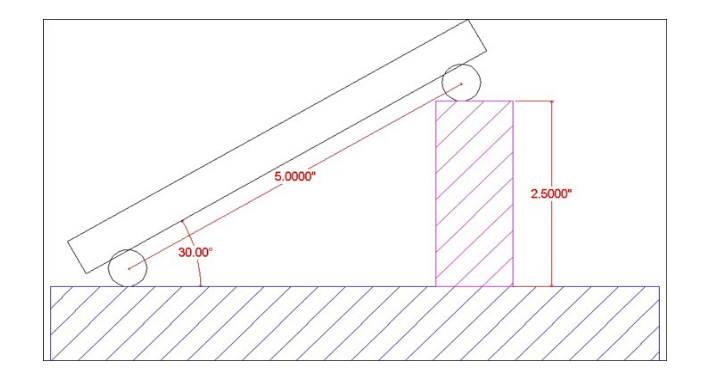
 25215 forum posts 3105 photos 1 articles | Some carefully calculated and placed packing will allow the who part to be set like a sine table to the various angles needed. That's assuming you don't have a mill the size of a Bridgeport and the large sine tables that fit them or a mill where the table can be inclined. Another option if your 4 holes are in the corners is to make two strips of say 20 x 20 that can be screwed to the back of the plate so they are parallel at each end. You can then use two vices, one to hold each strip and just set the plate to your angle and tighten the vices. Edited By JasonB on 07/10/2022 20:13:47 |
| Speedy Builder5 | 07/10/2022 20:06:51 |
| 2878 forum posts 248 photos | Chris, you don't say what sort of mill - can you tilt the head ? Use a tilting table ? |
| Jeff Dayman | 07/10/2022 20:27:08 |
| 2356 forum posts 47 photos | Another approach would be to bolt the plate flat on the mill and get some tapered endmills as shown on the attached link to make the angled oilways. The link is to a US site but I expect you can get them in the UK also, at suppliers to the injection mould making industry. Many angles of taper are available. https://www.mcmaster.com/draft-angle-endmills/high-speed-steel-tapered-square-end-mills/ |
| JasonB | 07/10/2022 20:36:13 |
25215 forum posts 3105 photos 1 articles | I think me and Speedy were thinking that the plate only needs tilting 1-10deg from horizontal which would be for shallow areas that slope and drain, the taper cutters would be more 1-10deg from vertical. Maybe Chris can post an image Thinking a bit more about using the 4 corner holes if you bolted round stock on then the whole thing just becomes a big sine plate, pack as required and clamp it down
|
| Jeff Dayman | 07/10/2022 21:12:16 |
| 2356 forum posts 47 photos | I guess I misinterpreted the OP's statement "but I need to mill at various angles, from 3-10 degrees to get the effects of the oil catch & flow going." When someone says "I need to mill at an angle" I envision angling the head, or using angled cutters, to make a milled feature with walls angled to the Z axis. If they say "I need to mill a sloping surface" then I envision a sine plate type setup as Jason sketched. Just based on my experience over the years in many shops. Your mileage may vary. |
| Chris Mate | 07/10/2022 22:30:44 |
| 325 forum posts 52 photos | Thanks for the advice, I was thinking too complicated. |
| Michael Gilligan | 08/10/2022 07:13:39 |
 23121 forum posts 1360 photos | Posted by Chris Mate on 07/10/2022 22:30:44:
. . That sounds good to me, Chris Watchmakers’ lathes feature a similar idea, called a Rose Cutter… it should only be a matter of making something along those lines, with a big hole where the pilot would be, and the right scale and proportions for your purpose [ of course if you have some exotic CNC machine, you just program it to whizz around everywhere ] MichaelG. .
. Credit: http://www.lathes.co.uk/watchmaker/page2.html |
| JasonB | 08/10/2022 07:32:28 |
25215 forum posts 3105 photos 1 articles | Put the plate on a rotary table, ctr each hole and then offset and mill around the hole. Or just counterbore the hole and Loctite in a "collar" Other option would be to use an "aircraft" counterbore without it's pilot or a hollow endmill
|
| Michael Gilligan | 08/10/2022 07:49:35 |
23121 forum posts 1360 photos | Posted by JasonB on 08/10/2022 07:32:28:
Put the plate on a rotary table, ctr each hole and then offset and mill around the hole. Or just counterbore the hole and Loctite in a "collar" Other option would be to use an "aircraft" counterbore without it's pilot or a hollow endmill
. [ref. your first option] Does Craig have a very big mill ? [quote] Measurements are roughly 340x 400 x 25mm [/quote] MichaelG. . Edit: __ ‘very big’ by my standards Edited By Michael Gilligan on 08/10/2022 07:53:06 |
| Circlip | 08/10/2022 09:31:01 |
| 1723 forum posts | A picture saves a thousand miss interpretations. Regards Ian. |
| Michael Gilligan | 08/10/2022 09:46:45 |
23121 forum posts 1360 photos | Posted by Circlip on 08/10/2022 09:31:01:
A picture saves a thousand miss interpretations. Regards Ian. . You could try this one: **LINK** https://www.model-engineer.co.uk/albums/member_photo.asp?a=56455&p=901582 … but it may not be the only Mill that Chris has access to. MichaelG. |
| KWIL | 08/10/2022 09:49:35 |
| 3681 forum posts 70 photos | I recently saw the use of Blue multi surface masking tape for holding down an aluminium plate on a mill. Tape the underside of Al plate, tape the top side of potentially sacrificial mountiing surface, superglue the two taped surfaces together using a weight. Then mill When finished, split the two tapes with a chisel. Not tried it yet but it worked OK |
| Circlip | 08/10/2022 10:02:05 |
| 1723 forum posts | What a beautiful picture of a milling machine MG but can't quite see the component the O/P is trying to copy.? Regards Ian. |
| Michael Gilligan | 08/10/2022 10:54:03 |
23121 forum posts 1360 photos | Posted by Circlip on 08/10/2022 10:02:05:
What a beautiful picture of a milling machine MG but can't quite see the component the O/P is trying to copy.? Regards Ian. . Sorry … I thought your comment related to my immediately-preceding post MichaelG. .
Edited By Michael Gilligan on 08/10/2022 10:59:27 |
| Chris Mate | 08/10/2022 20:20:51 |
| 325 forum posts 52 photos | Hi, I basicly will try to mill from a piece of aliminium as described before a one piece lid & functional oil catch plate, so the lid becomes a see through catchplate one piece with a manual mill. -So this may take some time to do. Where I need to I will make some experiments on seperate aliminium piece, like hole shapes. Edited By Chris Mate on 08/10/2022 20:22:55 |


Please login to post a reply.
Want the latest issue of Model Engineer or Model Engineers' Workshop? Use our magazine locator links to find your nearest stockist!
Sign up to our newsletter and get a free digital issue.
You can unsubscribe at anytime. View our privacy policy at www.mortons.co.uk/privacy
- hemingway ball turner
04/07/2025 14:40:26 - *Oct 2023: FORUM MIGRATION TIMELINE*
05/10/2023 07:57:11 - Making ER11 collet chuck
05/10/2023 07:56:24 - What did you do today? 2023
05/10/2023 07:25:01 - Orrery
05/10/2023 06:00:41 - Wera hand-tools
05/10/2023 05:47:07 - New member
05/10/2023 04:40:11 - Problems with external pot on at1 vfd
05/10/2023 00:06:32 - Drain plug
04/10/2023 23:36:17 - digi phase converter for 10 machines.....
04/10/2023 23:13:48 - More Latest Posts...
- View All Topics


- Reeves** - Rebuilt Royal Scot by Martin Evans
by John Broughton
£300.00 - BRITANNIA 5" GAUGE James Perrier
by Jon Seabright 1
£2,500.00 - Drill Grinder - for restoration
by Nigel Graham 2
£0.00 - WARCO WM18 MILLING MACHINE
by Alex Chudley
£1,200.00 - MYFORD SUPER 7 LATHE
by Alex Chudley
£2,000.00 - More "For Sale" Ads...
- D1-3 backplate
by Michael Horley
Price Not Specified - fixed steady for a Colchester bantam mark1 800
by George Jervis
Price Not Specified - lbsc pansy
by JACK SIDEBOTHAM
Price Not Specified - Pratt Burnerd multifit chuck key.
by Tim Riome
Price Not Specified - BANDSAW BLADE WELDER
by HUGH
Price Not Specified - More "Wanted" Ads...
Do you want to contact the Model Engineer and Model Engineers' Workshop team?
You can contact us by phone, mail or email about the magazines including becoming a contributor, submitting reader's letters or making queries about articles. You can also get in touch about this website, advertising or other general issues.
Click THIS LINK for full contact details.
For subscription issues please see THIS LINK.


 Register
 Log-in
Model Engineer Magazine
- Percival Marshall
- M.E. History
- LittleLEC
- M.E. Clock

ME Workshop
- An Adcock
- & Shipley
- Horizontal
- Mill

Subscribe Now
- Great savings
- Delivered to your door

Pre-order your copy!
- Delivered to your doorstep!
- Free UK delivery!