Forum sponsored by:

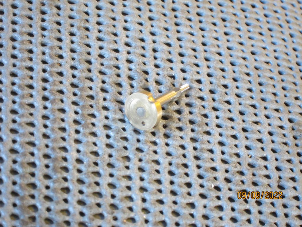
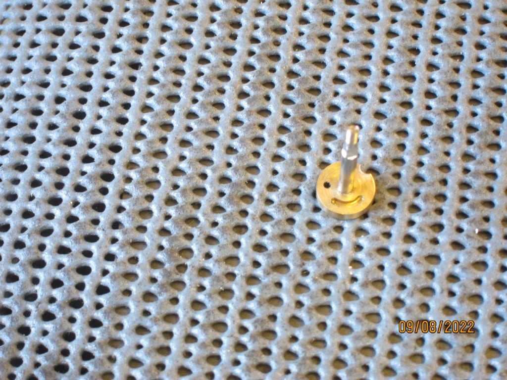
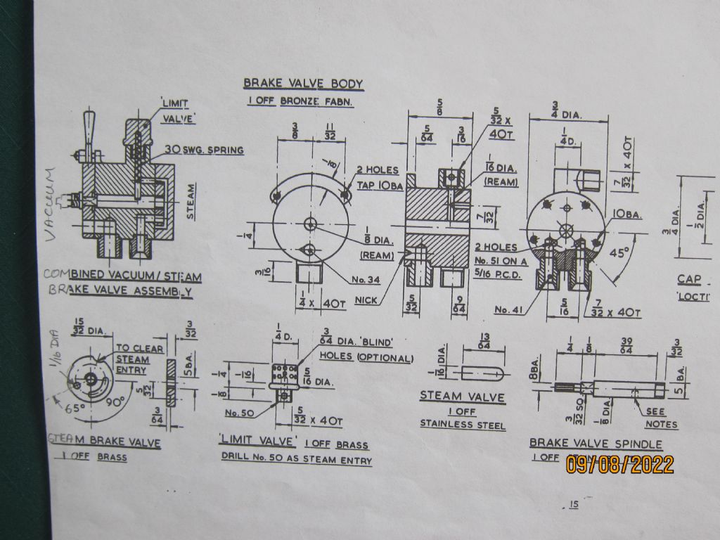
Don Young Combined Vacuum/Steam Brake Valve - Problems in achieving a tight fit between valve spindle and the steam brake valve
| Greensands | 09/08/2022 17:09:39 |
| 449 forum posts 72 photos |
|
| Jon Lawes | 09/08/2022 17:13:34 |
 1078 forum posts | To me that does look like a loctite job. |
| Jeff Dayman | 09/08/2022 17:59:56 |
| 2356 forum posts 47 photos | I'd try making the stem and disc in one piece out of a stainless steel bar a bit bigger than max OD of the disc. No joint means high strength and no chance of a leak between stem and disc. Free cutting stainless would be best. |
| JasonB | 09/08/2022 18:19:06 |
 25215 forum posts 3105 photos 1 articles | I thought the same at first Jeff but milling that little crescent shaped slot will be a pain with the shaft sticking up so far |
| Greensands | 09/08/2022 18:28:32 |
| 449 forum posts 72 photos | Given that the valve assembly will be in contact with hp steam, which grade of Loctite would the team suggest? |
| Jon Lawes | 09/08/2022 18:38:17 |
1078 forum posts | I think 272 has the highest rating. I've never tried it, but I have used Permabond HM162 with great results. It's more of an adhesive than a Threadlock though. |
| Jeff Dayman | 09/08/2022 19:24:24 |
| 2356 forum posts 47 photos | Jason - I did think about that, and a) I would EDM that slot in my shop, as I have an EDM machine I built. Or b) rearrange the design a bit to have just holes on the disc and move the slot to the fixed valve body. Many ways to skin a cat (as usual). |
| bernard towers | 09/08/2022 21:23:24 |
| 1221 forum posts 161 photos | Silver Solder? |
| Nigel Graham 2 | 09/08/2022 21:34:12 |
| 3293 forum posts 112 photos | High-temperature soft-solder would probably seal the thread perfectly well, but another sealant you could use is Steam Seal, or Foliac - graphite-loaded sealing paste made for, well, sealing steam-pipe joints! I forget where I bought my tin but it would have been one of "our" suppliers. |
| norm norton | 09/08/2022 22:19:14 |
| 202 forum posts 10 photos | Silver solder it. All the Loctites will soften at the temperature of pressurised steam, despite the temperature claims, and slowly fail. |
| Baz | 09/08/2022 22:24:05 |
| 1033 forum posts 2 photos | Plus one for silver soldering. |
| julian atkins | 10/08/2022 08:48:34 |
 1285 forum posts 353 photos | I've made at least 3, and silver solder. Lap with Brasso, making sure the Brasso remains wet, and only turn the disc the movement it makes in service |
| Greensands | 10/08/2022 12:27:31 |
| 449 forum posts 72 photos | Possibly one for Julian but I am open to all suggestions. Having made up the brake valve to the DY drawing I have been puzzled by the fact that when the valve is in the closed position, the steam port from the ‘Limit Valve’ is left slightly open thereby admitting steam into the end cap when I would have thought it should be left shut off. A dimensional check reveals that the radius to the outer edge of the steam port = 7/32 + 1/32 = 1/4 = 0.250” whereas the radius of the steam valve = 15/64 = 0.234” which results in a 0.016 overlap all of which seems to be borne out by the drawing. |
| martin haysom | 10/08/2022 12:46:14 |
 165 forum posts | Posted by JasonB on 09/08/2022 18:19:06:
I thought the same at first Jeff but milling that little crescent shaped slot will be a pain with the shaft sticking up so far could machine it with the shaft sticking down |
| Nigel Graham 2 | 10/08/2022 14:27:28 |
| 3293 forum posts 112 photos | Greensands - Without knowing the specific design here, is that slight opening to steam the "lap", or running, position, allowing a thread of steam though the brake cylinder to keep it hot? I think some miniature steam-brake valves have this so when the steam-brake is applied, it can work immediately and does not simply fill with condensate that would hamper both application and release. I have seen at least one commercially-made, model brake-valve with three positions: (Brake) ON, OFF and beyond that, LAP; but trying to verify this through the suppliers' catalogues proved fruitless. The official handbook for operating full-size locomotives, with their much more complicated fittings, makes no mention of this so possibly it was not necessary there. The steam-brake control was either ON or OFF! |
| julian atkins | 12/08/2022 08:35:26 |
1285 forum posts 353 photos | Hi Reg, I haven't made this particular design, and indeed I think we discussed your particular valve some time ago either on here or modelengproboards. The limit valve limits the vacuum. It should never have steam admitted to it. It is part of the vacuum brake system in effect a part of the vacuum brake pipe albeit here as part of the valve. I cannot see how you would be able to accurately make this limit valve to work. You would be better off making a separate limit valve as per the Hughes/Reeves design. Leave yours as a non working dummy. Additionally, something must be wrong somewhere if the valve disc is admitting steam to the vacuum part of the valve via the port for the vacuum system. I think you would be better off having a good look at Don Young's later 'E.S. Cox' and 'Doncaster' combined steam and vacuum brake valves. Don's 'Black 5' brake valve is a bit of a 'dog's dinner'. Cheers, Julian |
| Greensands | 12/08/2022 09:35:05 |
| 449 forum posts 72 photos | Hi Julian – Very pleased you have been able to pick up once again on this one. As I understand it, Dons' arrangement for the steam side of the combined brake valve, the so called ‘Limit Valve’ is a dummy fitting with blind perforations and is simply used as a convenient means of getting steam into the brake valve as described in LLAS No.55, Pages 33/34. It does however leave unanswered the question raised in my posting of the 10 Aug relating to the partial uncovering of the steam port when the valve is in the Off position. I need to have another look at his design for E.S.Cox but am under the impression that they were essentially the same design. |
Please login to post a reply.
Magazine Locator
Want the latest issue of Model Engineer or Model Engineers' Workshop? Use our magazine locator links to find your nearest stockist!
Sign up to our Newsletter
Sign up to our newsletter and get a free digital issue.
You can unsubscribe at anytime. View our privacy policy at www.mortons.co.uk/privacy
Latest Forum Posts
- *Oct 2023: FORUM MIGRATION TIMELINE*
05/10/2023 07:57:11 - Making ER11 collet chuck
05/10/2023 07:56:24 - What did you do today? 2023
05/10/2023 07:25:01 - Orrery
05/10/2023 06:00:41 - Wera hand-tools
05/10/2023 05:47:07 - New member
05/10/2023 04:40:11 - Problems with external pot on at1 vfd
05/10/2023 00:06:32 - Drain plug
04/10/2023 23:36:17 - digi phase converter for 10 machines.....
04/10/2023 23:13:48 - Winter Storage Of Locomotives
04/10/2023 21:02:11 - More Latest Posts...
- View All Topics
Support Our Partners


Shopping Partners
Subscription Offer

Latest "For Sale" Ads
- Reeves** - Rebuilt Royal Scot by Martin Evans
by John Broughton
£300.00 - BRITANNIA 5" GAUGE James Perrier
by Jon Seabright 1
£2,500.00 - Drill Grinder - for restoration
by Nigel Graham 2
£0.00 - WARCO WM18 MILLING MACHINE
by Alex Chudley
£1,200.00 - MYFORD SUPER 7 LATHE
by Alex Chudley
£2,000.00 - More "For Sale" Ads...
Latest "Wanted" Ads
- D1-3 backplate
by Michael Horley
Price Not Specified - fixed steady for a Colchester bantam mark1 800
by George Jervis
Price Not Specified - lbsc pansy
by JACK SIDEBOTHAM
Price Not Specified - Pratt Burnerd multifit chuck key.
by Tim Riome
Price Not Specified - BANDSAW BLADE WELDER
by HUGH
Price Not Specified - More "Wanted" Ads...
Get In Touch!
Do you want to contact the Model Engineer and Model Engineers' Workshop team?
You can contact us by phone, mail or email about the magazines including becoming a contributor, submitting reader's letters or making queries about articles. You can also get in touch about this website, advertising or other general issues.
Click THIS LINK for full contact details.
For subscription issues please see THIS LINK.
Digital Back Issues


Donate

 Register
 Log-in
Model Engineer Magazine
- Percival Marshall
- M.E. History
- LittleLEC
- M.E. Clock

ME Workshop
- An Adcock
- & Shipley
- Horizontal
- Mill

Subscribe Now
- Great savings
- Delivered to your door

Pre-order your copy!
- Delivered to your doorstep!
- Free UK delivery!
All Forum Topics > Locomotives > Don Young Combined Vacuum/Steam Brake Valve - Problems in achieving a tight fit between valve spindle and the steam brake valve