Forum sponsored by:

VFD Cable Supplier Recommendations
| Bountyboy | 20/06/2022 21:51:10 |
| 62 forum posts 8 photos | Hello, I'm in the process of fitting a VFD to my lathe. The VFD manufacturer states I need to use 3.5mm2 shielded twisted pairs cable between the motor and VFD. Does anyone know where I can purchase 2M of this special cable? I've tried RS, Farnell and general searches on the web but to no avail. Thanks in advance |
| Mike Poole | 20/06/2022 22:00:42 |
 3676 forum posts 82 photos | That sounds an odd spec for a power cable for a VFD to motor, do you have any details of the VFD? Mike |
| The Novice Engineer | 20/06/2022 23:03:10 |
| 85 forum posts 72 photos | When I connected my lathe and mill to their VFD's I used standard shielded/screened cable , for you 2M connection I feel you could use standard shielded / Screened cable. I used 4 Core 1.5mm2 - SY Multi Flex Cables , 18Amp capacity more than enough for a 1 HP motor 3.5mm2 is an odd specification the standard sizes are 1.5 , 2.5 , 4.0 6.0 I got mine from TLC Electrical Wholesale https://www.tlc-direct.co.uk For the signal cables for the Remote Control Box [ Stop Start Direction] I made twisted pair cables by using hook up flexible wire and twisting them together using a battery drill. I've also used Ethernet Cat5 Cable [4 twisted pairs] successfully This company has some interesting info on VFD cable https://www.elandcables.com/media/39064/variable-frequency-drive-vfd-emc-2yslcy-cable.pdf Steve
|
| Ian P | 21/06/2022 12:25:17 |
 2747 forum posts 123 photos | Posted by Bountyboy on 20/06/2022 21:51:10:
Hello, I'm in the process of fitting a VFD to my lathe. The VFD manufacturer states I need to use 3.5mm2 shielded twisted pairs cable between the motor and VFD. Does anyone know where I can purchase 2M of this special cable? I've tried RS, Farnell and general searches on the web but to no avail. Thanks in advance As Mike said that is an odd type of cable, so odd that it probably does not exist. Ian P |
| not done it yet | 21/06/2022 12:47:15 |
| 7517 forum posts 20 photos | Spec for the SB 1024 says no more than two horse power motor. That would not require such large cross section conductors for its three phases. |
| ChrisB | 21/06/2022 13:42:25 |
| 671 forum posts 212 photos | This **LINK** is the cable I got for a 1.5kw motor and Invertek VFD. I went with 2.5mm wire but 1.5mm would have been just as fine. You don't mention the power for the vfd and motor? |
| SillyOldDuffer | 21/06/2022 13:46:36 |
| 10668 forum posts 2415 photos | Posted by not done it yet on 21/06/2022 12:47:15:
Spec for the SB 1024 says no more than two horse power motor. That would not require such large cross section conductors for its three phases. The motor wouldn't, but the cable requirement might be related to keeping EMC levels down. Although VFD's produce power good enough to fool a motor it's being fed genuine 3-phase, the waveform is synthesised. Full of high-speed switching artefacts, and there's plenty of radio frequency power in the mix. High frequency AC behaves very differently from low frequency AC, such as radiating from relatively short lengths of cable. The purpose of using fat section cable might be to keep the RF impedance low, perhaps matching it to reduce reflections, and improving the efficiency of the shield. I used 2.5mm² 4 core SY (from TLC as it happens), which is good for 24A, and should work fine. 6mm² shielded is available if fatter is essential. I wondered if two different cable requirements are mixed up. The controls are likely to call for twisted pair, and the usual shielded power cable is needed by the motor. Not a special twisted-pair shielded power cable! Dave |
| Mike Poole | 21/06/2022 15:47:19 |
3676 forum posts 82 photos | SY cable has a braided steel layer which is designed for mechanical protection, CY has a copper screen which is intended for suppression. SY is probably fairly effective at controlling radiated noise but it’s primary function is mechanical protection. Mike |
| not done it yet | 21/06/2022 20:20:28 |
| 7517 forum posts 20 photos | Posted by SillyOldDuffer on 21/06/2022 13:46:36:
Posted by not done it yet on 21/06/2022 12:47:15:
Spec for the SB 1024 says no more than two horse power motor. That would not require such large cross section conductors for its three phases. The motor wouldn't, but the cable requirement might be related to keeping EMC levels down. Although VFD's produce power good enough to fool a motor it's being fed genuine 3-phase, the waveform is synthesised. Full of high-speed switching artefacts, and there's plenty of radio frequency power in the mix. High frequency AC behaves very differently from low frequency AC, such as radiating from relatively short lengths of cable. The purpose of using fat section cable might be to keep the RF impedance low, perhaps matching it to reduce reflections, and improving the efficiency of the shield. I used 2.5mm² 4 core SY (from TLC as it happens), which is good for 24A, and should work fine. 6mm² shielded is available if fatter is essential. I wondered if two different cable requirements are mixed up. The controls are likely to call for twisted pair, and the usual shielded power cable is needed by the motor. Not a special twisted-pair shielded power cable! Dave Doubtful. Radio waves, from an capacitance/inductance system (aerial) also depends on the length of the antenna rods. I doubt very much that choosing a slightly bigger cross section would make any difference at all. Anything radiated would likely be at any random frequency.- likely dependant on the length of the lead, if it is not properly screened. It’s OK twisting pairs, but for three phase there would be a spare one, so you are likely correct that the poster is confused. |
| Robert Atkinson 2 | 21/06/2022 20:56:21 |
 1891 forum posts 37 photos | Twisted pairs are not suitable for reducing interference on 3 pahse circuits like VFD to motor. For twisted cable to be effective the signal on the conductors should be balanced. For two core thai is easy to understand the fields from the conductor carrying current out are cancelled by the fields caused by the current coming back. You can see this with a compass, a few feet of wire and a AA cell. lay the wire in a big loop with the compass 1/4 way along the wire. Connect the cell for a second (yes a short circuit) and the compass will deflect. Now bring the last 1/4 of the wire and lay it close to the fist part without moving the first wire or compass. Connect the battery for a second and the compass deflection will be much less. Twist the two wires together as they pass the compass and there will be no deflection. As others have mentioned a length of 2.5 mm 4 core SY cable (i also use TLC for short lengths ) https://www.tlc-direct.co.uk/Products/MF2dot5slash4.html Is perfectly adequate for your application.
Robert G8RPI. |
| iNf | 22/06/2022 20:32:02 |
| 58 forum posts 46 photos | If you have a local CEF you could save postage |
| SillyOldDuffer | 22/06/2022 21:25:17 |
| 10668 forum posts 2415 photos | Posted by not done it yet on 21/06/2022 20:20:28:
Posted by SillyOldDuffer on 21/06/2022 13:46:36:
Posted by not done it yet on 21/06/2022 12:47:15:
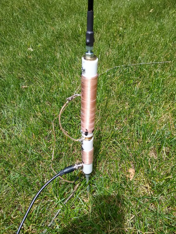
Spec for the SB 1024 says no more than two horse power motor. That would not require such large cross section conductors for its three phases. The motor wouldn't, but the cable requirement might be related to keeping EMC levels down. ...Doubtful. Radio waves, from an capacitance/inductance system (aerial) also depends on the length of the antenna rods. I doubt very much that choosing a slightly bigger cross section would make any difference at all. Anything radiated would likely be at any random frequency.- likely dependant on the length of the lead, if it is not properly screened. ... I'm not convinced fatter wires would make much difference either, but the frequency at which radiation is most efficiently radiated depends on the inductance of the motor windings as well as the wiring. Whatever the resonant frequency happens to be isn't primarily determined by the length of the wires, because their inductance and capacitance are small compared with the rest of the circuit, including the motor. Loading coils are often added to antennas reduce the amount of metal needed in the air because there isn't enough real estate or weight carrying capability to support a full-size resonant aerial.
The loading coil in the photo above isn't only an inductance calculated to make a short antenna resonant: equally important, it's designed to transform the antenna's impedance to match the 50 ohm coaxial feeder cable. (Black Wire at the base.) If the feeder and antenna impedances aren't matched standing waves appear on the outside of the coaxial cable's shield and it radiates like the clappers - it's bad. Something like that might explain the VFD cable's odd specification, it's part of an EMC strategy. Or might be a misprint... Dave
Edited By SillyOldDuffer on 22/06/2022 21:28:22 |
Please login to post a reply.
Magazine Locator
Want the latest issue of Model Engineer or Model Engineers' Workshop? Use our magazine locator links to find your nearest stockist!
Sign up to our Newsletter
Sign up to our newsletter and get a free digital issue.
You can unsubscribe at anytime. View our privacy policy at www.mortons.co.uk/privacy
Latest Forum Posts
- *Oct 2023: FORUM MIGRATION TIMELINE*
05/10/2023 07:57:11 - Making ER11 collet chuck
05/10/2023 07:56:24 - What did you do today? 2023
05/10/2023 07:25:01 - Orrery
05/10/2023 06:00:41 - Wera hand-tools
05/10/2023 05:47:07 - New member
05/10/2023 04:40:11 - Problems with external pot on at1 vfd
05/10/2023 00:06:32 - Drain plug
04/10/2023 23:36:17 - digi phase converter for 10 machines.....
04/10/2023 23:13:48 - Winter Storage Of Locomotives
04/10/2023 21:02:11 - More Latest Posts...
- View All Topics
Support Our Partners


Shopping Partners
Subscription Offer

Latest "For Sale" Ads
- Reeves** - Rebuilt Royal Scot by Martin Evans
by John Broughton
£300.00 - BRITANNIA 5" GAUGE James Perrier
by Jon Seabright 1
£2,500.00 - Drill Grinder - for restoration
by Nigel Graham 2
£0.00 - WARCO WM18 MILLING MACHINE
by Alex Chudley
£1,200.00 - MYFORD SUPER 7 LATHE
by Alex Chudley
£2,000.00 - More "For Sale" Ads...
Latest "Wanted" Ads
- D1-3 backplate
by Michael Horley
Price Not Specified - fixed steady for a Colchester bantam mark1 800
by George Jervis
Price Not Specified - lbsc pansy
by JACK SIDEBOTHAM
Price Not Specified - Pratt Burnerd multifit chuck key.
by Tim Riome
Price Not Specified - BANDSAW BLADE WELDER
by HUGH
Price Not Specified - More "Wanted" Ads...
Get In Touch!
Do you want to contact the Model Engineer and Model Engineers' Workshop team?
You can contact us by phone, mail or email about the magazines including becoming a contributor, submitting reader's letters or making queries about articles. You can also get in touch about this website, advertising or other general issues.
Click THIS LINK for full contact details.
For subscription issues please see THIS LINK.
Digital Back Issues


Donate

 Register
 Log-in
Model Engineer Magazine
- Percival Marshall
- M.E. History
- LittleLEC
- M.E. Clock

ME Workshop
- An Adcock
- & Shipley
- Horizontal
- Mill

Subscribe Now
- Great savings
- Delivered to your door

Pre-order your copy!
- Delivered to your doorstep!
- Free UK delivery!
All Forum Topics > Electronics in the Workshop > VFD Cable Supplier Recommendations