Forum sponsored by:

Help with Excel
| steamdave | 21/03/2022 13:00:34 |
| 526 forum posts 45 photos | I need to machine a .375" concave arc in aluminium.
I consider the radius too large for a form tool because there is not a lot of metal to hold in the chuck, although the small end will be supported by a centre. So, I would like to create a table in Excel to give me the cross slide and longitudinal infeeds. The tool width will be 3/32" and the curve will be smoothed afterwards with a file and emery cloth. Searching Google, I can only find info on drawing freeform arcs. Can anyone explain how to make the required table, or point me to an online instruction. I don't have any CAD programmes. Dave
|
| John Haine | 21/03/2022 13:29:44 |
| 5563 forum posts 322 photos | Is it the formula you need help with, or writing the spreadsheet, or both? |
| John Haine | 21/03/2022 13:30:43 |
| 5563 forum posts 322 photos | Is it the formula you need help with, or writing the spreadsheet, or both? |
| Andy_G | 21/03/2022 13:54:21 |
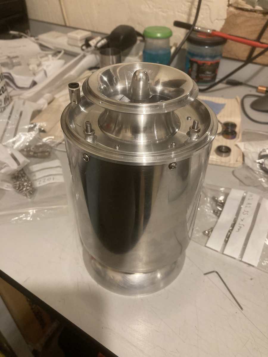
 260 forum posts | You can work out the X-Y coordinates of the surface from the formula for a circle (X^2 + Y^2 = R^2) where the origin is the centre of the arc. It's easiest to work with a round tool (e.g. a pattern following tool or a carbide button). Translating the surface coordinates of a concave surface to the centre point of a tool of radius r then boils down to scaling the X & Y coordinates by R/(R+r). You can then choose a known reference position and offset the coordinates wrt this to get your cross slide and feed readings. The devil is in the detail in getting the sign conventions correct! I used this method to turn some accurate curves in my model jet engine - there's a fairly detailed description part way down this page https://misterg.org.uk/turbine-html-16/ I find it easiest to set the top slide parallel to the bed and use this for the Z feed, rather than the carriage. I set a stop on the lathe bed where the tool just touches the face of the part and zero the top slide dial. Cross slide dial is zeroed by touching off on the OD. I can then wind the carriage back, increment the cross slide and set the desired Z travel on the top slide without cutting any metal whilst making the adjustment. I have also sent you a PM
Andy Edited By Andy_G on 21/03/2022 13:57:13 |
| steamdave | 21/03/2022 14:10:56 |
| 526 forum posts 45 photos | John, I need help with both formula writing and the spreadsheet. Andy says he will send me a spreadsheet, so I'll see how that goes before getting back to you. Dave |
| Emgee | 21/03/2022 14:23:01 |
| 2610 forum posts 312 photos | Dave Here is a starting point in mm Emgee
|
| DC31k | 21/03/2022 14:45:24 |
| 1186 forum posts 11 photos | Does anyone else find it slightly strange that the question was posed in imperial units and the diagram above is in metric? Clearly an engineer at work - perfectly correct but entirely unhelpful. Anyway, if you want some magic words for Google, 'lautard radius turning' will help. Of particular note are: http://www.swarfology.com/sphere1.pdf https://rick.sparber.org/BTMNC.pdf Edited By DC31k on 21/03/2022 14:46:21 |
| bernard towers | 21/03/2022 15:57:24 |
| 1221 forum posts 161 photos | Do your smoothing with a round graver, much more control and vision about what's going on. |
| JasonB | 21/03/2022 16:02:08 |
 25215 forum posts 3105 photos 1 articles | Dave, is that a square ended 3/32" tool or a rounded end or even one with some radius to the corner as each will need different allowances when working out the cut. |
| steamdave | 21/03/2022 16:27:01 |
| 526 forum posts 45 photos | DC I know where you are coming from, but although I'm not good with maths I can use a calculator to convert from Metric to Imperial. In the end, I doubt that a thou or two either way will be noticed after it is covered in paint. Thanks for the links. JB Following a suggestion, I'll use a button tool to do the cutting. Bernard. I'd thought of using a graver but access is too restricted (There are actually two parts end to end, to be split later). Dave |
| Emgee | 21/03/2022 16:42:27 |
| 2610 forum posts 312 photos | Dave, same drawing in imperial but to only 2 decimal places, also added 3 more stations to cut to, hope it helps. Emgee
|
| Nealeb | 21/03/2022 16:58:58 |
| 231 forum posts | Unfortunately, while it's pretty simple trigonometry to work out the coordinates of the curve, those aren't quite the coordinates that you need to machine said curve! Possibly not even good enough (given that this curve swings through near 90deg) for this cosmetic-not-bearing-surface curve. The reason is that in order to position the tool, assuming that you are using a circular button tool, you need the coords of the centre point of the tool. The actual contact point - where the cutting takes place - is a bit more difficult to calculate than just the curve itself as there is an offset of tool position from the curve that depends on the curvature of that curve at a given point. At the largest end of the curve you are using the side of the tool so need to offset along the lathe axis while at the small end this offset is near zero but the infeed offset is now maximum - and these change all the way along. It's unfortunate that the OP is not a CAD user. I reckon the easiest way to get the required list of coordinates is to draw the profile in CAD and use its CAM module to calculate the path. I guess you could do this by generating the lathe tool path needed although not having any experience of doing that, I would pretend that the profile is going to be machined on a mill, specify a tool of the diameter of my lathe tool button, and generate the gcode accordingly. It's then easy enough to edit out the XY coordinates from the gcode and put that into a spreadsheet - or just print as text. I'm sure I could do the work needed to come up with a formula for the correct tool path manually but it's very much a case of letting the software and the PC take the strain, and a whole lot less error-prone! For doubters, I (and plenty of others) have taken this path to get "manual numerical control" coordinates before; I use the technique to machine loco wheel flanges because I'm a whole lot better with CAD/CAM than I am grinding a form tool... A DRO on the lathe helps a lot as well. |
| Andy_G | 21/03/2022 17:29:20 |
260 forum posts | Posted by Nealeb on 21/03/2022 16:58:58:
The reason is that in order to position the tool, assuming that you are using a circular button tool, you need the coords of the centre point of the tool. The actual contact point - where the cutting takes place - is a bit more difficult to calculate than just the curve itself as there is an offset of tool position from the curve that depends on the curvature of that curve at a given point. With a circular arc and a circular tool, the XY coordinates of the tool centre point wrt the arc centre point are honestly just the XY coordinates of the arc multiplied or divided* by [arc radius] / ([Tool radius] + [arc radius]) The proof / derivation is via similar triangles. These coordinates (relative to the arc centre) then need to be translated into X,Y (or X,Z) tool movements relative to a datum position. *Depending on whether the cut surface is concave or convex All the following were cut this way with 0.2mm step in X and a 6mm diameter button tool
8mm external convex radius:
20mm internal convex radius
External concave radius
8mm internal concave radius
17.85 mm internal convex radius
etc...
Edited By Andy_G on 21/03/2022 17:34:14 |
| Nealeb | 21/03/2022 17:46:55 |
| 231 forum posts | No argument, Andy - I was thinking "general case" but if you are cutting a truly circular arc, then the tool path follows a similar arc struck from the same centre but reduced by the radius of the cutter. I had completely missed the "special case" nature of this one where the sums actually become very easy. The technique that I described is of use for anything other than a circular arc - possibly for aesthetic reasons it is a part-ellipse, for example. My loco wheel flanges fall into this category. All the same, personally speaking, I would probably still use the CAD/CAM route, justified by this quote from Leibniz: "It is unworthy of excellent men to lose hours like slaves in the labour of calculation which could safely be relegated to anyone else if machines were used."I guess that it's the difference between needing to look for an elegant solution to avoid lots of calculation or similar effort, and just throwing lots of CPU cycles at a brute-force solution! |
| Andy_G | 21/03/2022 18:25:04 |
260 forum posts | Posted by Nealeb on 21/03/2022 17:46:55:
No argument, Andy - I was thinking "general case" Absolutely! A general solution is much more complicated.than my description
FWIW I've sent Dave the spreadsheet I used. It remains to be seen whether anyone other than the author can make head or tail of it! Andy |
| JasonB | 21/03/2022 19:18:35 |
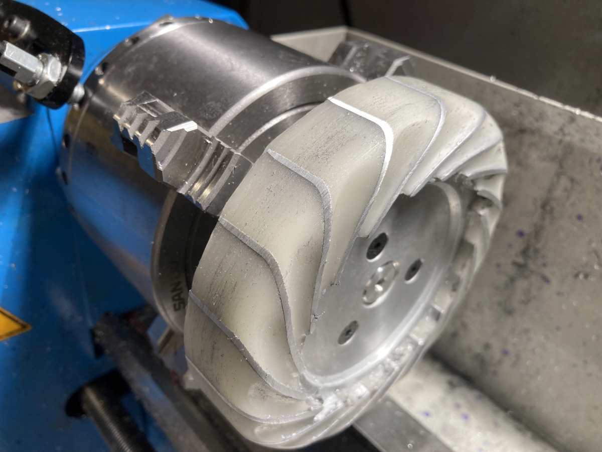
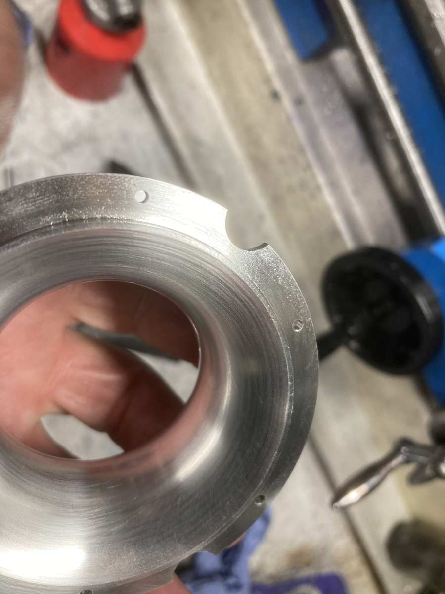
25215 forum posts 3105 photos 1 articles | In practical use on a manual machine it's often easier to use the side of the tool as the ref that way you simply touch the tool and set your handwheel or DRO. So for Dave'd job he needs to generate the curved surface with a series of cuts from his button tool. I do hope it's a RCMT06 or RCGT06 as that's what I have worked it out for.
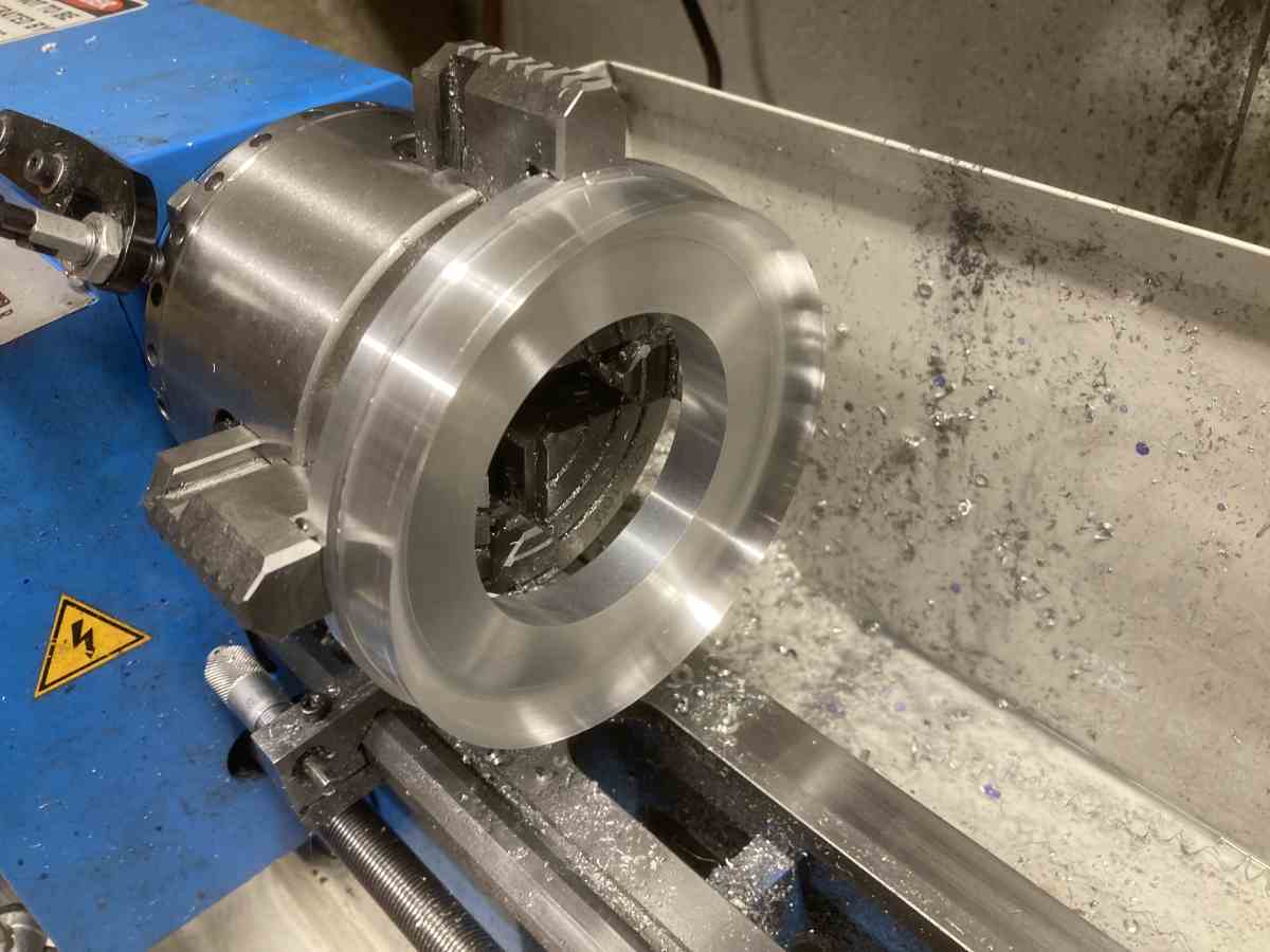
First turn your stock so it looks like this and then mount up your button tool. With topslide set parallel to lathe axis touch against the diameter and set your cross slide handwheel or DRO to zero. Then touch the side of the tool against the face and set handwheel to
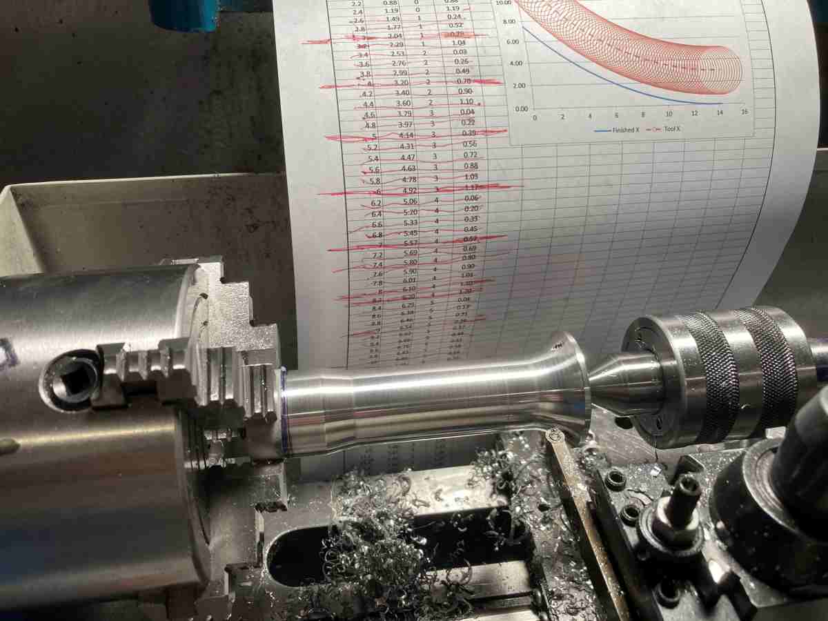
Then wind in the topslide to 0.000 and feed tool in 0.375. Topslide to 0.025 and feed in to 0.375. etc After a while the cross slide feed in will start to reduce but just keep winding in the topslide in 25thou increments as per table. The last cut will be with the dial reading 0.082
This is what it takes to get the dims in the table, did someone mention cluttered drawings
Edited By JasonB on 22/03/2022 07:11:20 |
| steamdave | 21/03/2022 21:05:54 |
| 526 forum posts 45 photos | Well, there's plenty of food for thought in those replies! Dave |
| Paul Lousick | 21/03/2022 21:17:23 |
| 2276 forum posts 801 photos | You could also machine the curve on a milling machine with a rotary table and a 3/4" dia cutter |
| JasonB | 22/03/2022 07:08:19 |
25215 forum posts 3105 photos 1 articles | Dave, as no one spotted it I've just altered an error in my post
Topslide should be set to 0.082 not 0.088 |
| steamdave | 03/04/2022 10:33:28 |
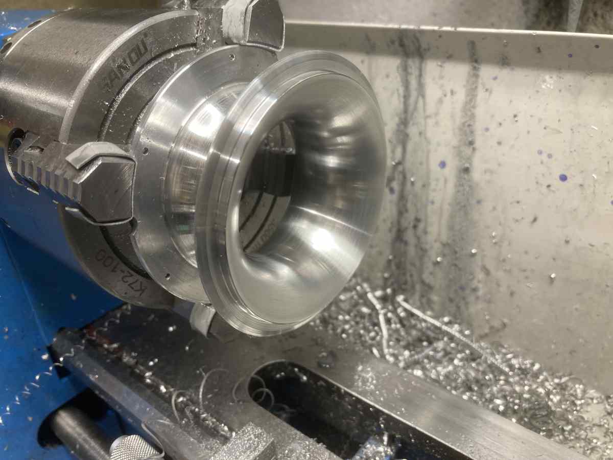
| 526 forum posts 45 photos | At long last, I have machined the .375" concave radius in the parts that I was making.
Thanks to all the suggestions and help offered. Dave |


Please login to post a reply.
Magazine Locator
Want the latest issue of Model Engineer or Model Engineers' Workshop? Use our magazine locator links to find your nearest stockist!
Sign up to our Newsletter
Sign up to our newsletter and get a free digital issue.
You can unsubscribe at anytime. View our privacy policy at www.mortons.co.uk/privacy
Latest Forum Posts
- *Oct 2023: FORUM MIGRATION TIMELINE*
05/10/2023 07:57:11 - Making ER11 collet chuck
05/10/2023 07:56:24 - What did you do today? 2023
05/10/2023 07:25:01 - Orrery
05/10/2023 06:00:41 - Wera hand-tools
05/10/2023 05:47:07 - New member
05/10/2023 04:40:11 - Problems with external pot on at1 vfd
05/10/2023 00:06:32 - Drain plug
04/10/2023 23:36:17 - digi phase converter for 10 machines.....
04/10/2023 23:13:48 - Winter Storage Of Locomotives
04/10/2023 21:02:11 - More Latest Posts...
- View All Topics
Support Our Partners


Shopping Partners
Subscription Offer

Latest "For Sale" Ads
- Reeves** - Rebuilt Royal Scot by Martin Evans
by John Broughton
£300.00 - BRITANNIA 5" GAUGE James Perrier
by Jon Seabright 1
£2,500.00 - Drill Grinder - for restoration
by Nigel Graham 2
£0.00 - WARCO WM18 MILLING MACHINE
by Alex Chudley
£1,200.00 - MYFORD SUPER 7 LATHE
by Alex Chudley
£2,000.00 - More "For Sale" Ads...
Latest "Wanted" Ads
- D1-3 backplate
by Michael Horley
Price Not Specified - fixed steady for a Colchester bantam mark1 800
by George Jervis
Price Not Specified - lbsc pansy
by JACK SIDEBOTHAM
Price Not Specified - Pratt Burnerd multifit chuck key.
by Tim Riome
Price Not Specified - BANDSAW BLADE WELDER
by HUGH
Price Not Specified - More "Wanted" Ads...
Get In Touch!
Do you want to contact the Model Engineer and Model Engineers' Workshop team?
You can contact us by phone, mail or email about the magazines including becoming a contributor, submitting reader's letters or making queries about articles. You can also get in touch about this website, advertising or other general issues.
Click THIS LINK for full contact details.
For subscription issues please see THIS LINK.
Digital Back Issues


Donate

 Register
 Log-in
Model Engineer Magazine
- Percival Marshall
- M.E. History
- LittleLEC
- M.E. Clock

ME Workshop
- An Adcock
- & Shipley
- Horizontal
- Mill

Subscribe Now
- Great savings
- Delivered to your door

Pre-order your copy!
- Delivered to your doorstep!
- Free UK delivery!
All Forum Topics > CAD - Technical drawing & design > Help with Excel