Forum sponsored by:

Cross-slide fixture plate considerations
| Calum Galleitch | 06/03/2022 13:52:11 |
 195 forum posts 65 photos | As a milling machine is not an option for the foreseeable, I'd like to undertake light milling operations in the lathe as well as other operations involving attaching things to the cross-slide. However, the cross-slide on my lathe is not big enough to consider adding T-slots. In the long run manufacturing a replacement cross-slide would be ideal, but I'd need both a big enough mill and the skills to do it!
So my thought is to make a fixture plate in aluminium which would be bolted to the cross-slide. I don't require repeatability of fixturing, I think, so the aim is purely to create a secure platform to hold things down. The cross slide is something like 350x120mm: so my first questions are: how thick should the plate be, and how securely should it be attached, to be reasonably rigid? Recognising of course that "rigid" is a relative concept! I don't imagine myself milling to accuracies of a tenth: more like holding a vertical milling slide to make things like T-nuts or a QCTP. I was thinking that six mounting holes in total would be adequate, in the corners and half-way along. Looking online I see I can get a bit of 16mm plate for about £35. I am thinking of an array of tapped M10 holes at say 30mm centres - does this seem reasonable? Or would it be simpler and more flexible to just drill and tap holes as and when I need them? Tap drilling aluminium: I may be looking in the wrong places but aluminium drills in 0.1mm increments don't seem to exist. I can find an 8.8mm carbide stub drill on eBay: to go through say 16mm, will this be up to the job for say 40-odd holes?
|
| David Senior | 06/03/2022 13:59:40 |
| 30 forum posts 8 photos | Can't offer any advice on the main part of your question, but Cutwel do 8.8mm in their aluminium specific range, though I am not sure why you wouldn't use a standard jobber for this, and I wouldn't expect any issues with the life of the drill Dave |
| Clive Foster | 06/03/2022 14:21:19 |
| 3630 forum posts 128 photos | Calum Maybe consider one of the solid aluminium breadboards from Thor labs as an alternative to making your own. https://www.thorlabs.com/newgrouppage9.cfm?objectgroup_id=159 Only 1/2" thick and holes are M6 on 25 mm centres rather than your preferred 10 mm but its a lot easier to buy pre-holed rather than DIY and the extra cost / less work ratio doesn't seen stupidly unfavourable. Thor were quite happy to take my crdit card for a one off some time back. Newport supply similar things at similar prices but I've not bouhgt from them direct via credit card. https://www.newport.com/f/sa2-solid-aluminum-optical-breadboard-plates Regards Clive |
| Michael Gilligan | 06/03/2022 14:27:52 |
 23121 forum posts 1360 photos | Whether you make or buy … I think an array of M6 holes should be adequate for ‘realistic’ milling-in-the-lathe MichaelG. |
| SillyOldDuffer | 06/03/2022 15:09:15 |
| 10668 forum posts 2415 photos | Difficult to know what to advise. On the plus side, Calum has a hefty lathe, on the downside, he can't just bolt a milling vice to the saddle. Having to spending time and money making a suitable mounting is a negative, especially as milling on a lathe is marginal at best. I don't think whatever is added to the saddle will improve rigidity. Milling on lathes does work, but it's very restricting. A lathe can't provide the rigidity or space of a real mill. It works up to a point, but is very fussy. Due to multiple limitations I found milling on a lathe extremely frustrating. I think most people are disappointed by it. Trouble is, lathe milling is grossly inferior to a real milling machine. It's because lathes fundamentally aren't designed for milling. And mills don't make good lathes either! How much the inferiority matters depends entirely on the work being done. Might be perfectly acceptable for occasional light milling of small objects. Unfortunately, there's a high risk of the operator finding lathe milling unacceptable. Hard to predict because many disadvantages only appear when lathe milling is tried. For example, it takes an age to get the work-holding sorted out, then only light cuts can be taken because rigidity ls lacking, and then the job has to be remounted several times because there isn't enough saddle or up/down movement available. Lathe milling looks reasonable in theory but the compromise struggles to cut metal satisfactorily. Give it a try by all means, but I predict disappointment. I discovered it was better to put the money towards a milling machine. Dave |
| Howard Lewis | 06/03/2022 15:22:44 |
| 7227 forum posts 21 photos | S O D sums it up pretty well. VERY occasionally, I have used a lathe for milling, or better for co ordinate drilling, when the job could not fit under the mill. As SOD says, rigidity is inferior to using the proper machine. Where needs must, and the devil drives, it may be possible to remove the Top Slide and fit a Vertical Slide in some way. This would give you graduated movements, hopefully, in two planes, but any angular work would require careful setting.. By compromising rigidity even more, it may be possible to make up an adaptor plate to carry a Vertical Slide in the Toolpost. This might allow a limited amount of offsetting for milling at an angle. But ultimately, neither of these will be as suitable as a proper milling machine, or capable of anything but light work. Howard. |
| Calum Galleitch | 06/03/2022 15:33:17 |
195 forum posts 65 photos | Yes, my only reason for using M10 is I have about fifteen metres of stud lying around! I do like the idea of a pre-made plate - shame the sizes don't quite match up but surely manageable. Clive, do you find 1/2" thick enough? Certainly seems like it should but I don't like to guess. |
| Clive Foster | 06/03/2022 15:36:49 |
| 3630 forum posts 128 photos | Harrison offered a vertical slide as an official accessory for the L5 machines which are of similar size to Calums Cub. The was one with the L5 we had in the section workshop at RARDE but it was never, to my knowledge at least, used. Pretty hefty piece of kit. Bolted on in place of the topslide. Calum I've only used the Thor Labs breadboards as fixture plates. Certainly fine for anything I wanted to do but all small stuff where standard vices and Bridgeport slot fitting clamp sets were too cumbersome. 6 mm in alloy is pretty darn strong if you get a solid face to face joint and reasonably filled hole or slot. Clive Edited By Clive Foster on 06/03/2022 15:43:37 |
| Calum Galleitch | 06/03/2022 15:45:51 |
195 forum posts 65 photos | Crossposted with S.O.D. and Howard! Yes, absolutely agree it's not ideal - I just don't have the space for a mill that isn't itself a toy at the moment. At some point I'd like to do some building work to extend sideways - half the building my workshop is in is a bare earth floor former barn but the front (stone) wall will need a complete rebuild, floor concreted, internal wall taken down and a roller shutter installed (so I can bring the mill in I did look at some kind of adaption of the toolpost but the cross-slide travel is relatively limited, so the toolpost itself doesn't quite reach the lathe centre. |
| JasonB | 06/03/2022 15:54:47 |
 25215 forum posts 3105 photos 1 articles | You don't need special drills for aluminium half decent HSS will be fine. As you are going to be clamping things down to it I would go with more engagement and drill 8.5mm and tap with either a spiral flute or spiral point tap. Split point stub length should not even need punching or a ctr drill to start, something like these and one drill bit will do all your holes and more without need to sharpen.. Use a little paraffin to lubricate. I've a couple of 1o and 12mm steel plates that I use a machining plate so your 16mm ali should be a similar strength |
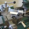
| John P | 06/03/2022 16:49:35 |
| 451 forum posts 268 photos | Posted by Calum Galleitch 06/03/2022 13:52:11
So my thought is to make a fixture plate in aluminium which would be bolted to the cross-slide. The cross slide is something like 350x120mm: so my first questions are: how thick Looking online I see I can get a bit of 16mm plate for about £35. I am thinking Tap drilling aluminium: I may be looking in the wrong places but aluminium ------------------------------------------- I think you will need to re think the "I was thinking that six mounting holes in total would be adequate, as you will find the cross slide at the back end is just a thin shell to cover the lead screw over John
|
| Alan Jackson | 06/03/2022 17:28:20 |
 276 forum posts 149 photos | Callum, I have added tee slots to my Colchester Chipmaster lathe. You may not want to go this far but it has proved to be very useful for all sorts of machining operations. It did also involve making a new topslide which can be moved and locked anywhere on the cross slide. Alan
|
| Calum Galleitch | 06/03/2022 18:38:31 |
195 forum posts 65 photos | John, thank you, I was hoping you might be able to chip in! I've not yet had the cross-slide off, so that is good to know. I had assumed the cross-section would be constant all the way along. Alan, that's beautiful looking work (as always!) I absolutely agree, a T-slotted cross-slide would be perfect. The existing cross slide has no material to spare (it's the same as John's picture, above) and I don't currently have the facilities to manufacture a complete replacement, which would require a new toolpost and possibly compound, as well. I'm sure this will be one of my first projects when I get a mill organised!
|
| Michael Gilligan | 06/03/2022 19:07:10 |
23121 forum posts 1360 photos | Posted by John P on 06/03/2022 16:49:35:
[…] The cross slides on these machines are not that rigid ,a thick steel plate would be more the thing to go for if you are unable to machine a cast plate as i have ,the aluminium plate will add little to the rigidity of the cross slide. . It may be worth noting that the ‘specific stiffness’ [i.e. stiffness to weight ratio] of the hard Aluminium alloys is, to a reasonable approximation, equal to that of steel. … and they’re much nicer to machine ! A thick Aluminium alloy plate might therefore be preferable, if there is ample space. MichaelG. . Edit: __ doubters might like to look here: http://www-materials.eng.cam.ac.uk/mpsite/interactive_charts/spec-spec/NS6Chart.html .
Edited By Michael Gilligan on 06/03/2022 19:22:31 |
| Andy Stopford | 06/03/2022 19:18:49 |
| 241 forum posts 35 photos | I'd suggest drilling and tapping the holes as and when you need them. I've made 'universal' pre-tapped fixture plates in the past, and the holes never seem to be in the right place. |
| John P | 06/03/2022 20:53:25 |
| 451 forum posts 268 photos | I should have added in the last post on this about using John
|
| Peter Cook 6 | 06/03/2022 21:16:46 |
| 462 forum posts 113 photos | Interesting discussion, but simply adding a fixture plate doesn't give any Z-axis control. I would have thought for any realistic milling use you would be far better off with a vertical slide (with T-slots?) to which you can afix the workpiece or a small milling vice. |
| JasonB | 07/03/2022 06:56:27 |
25215 forum posts 3105 photos 1 articles | You need the table to fix a vertical slide to. As the OP said "I don't imagine myself milling to accuracies of a tenth: more like holding a vertical milling slide to make things" |
| David George 1 | 07/03/2022 07:17:06 |
 2110 forum posts 565 photos | I bought a piece of gauge plate for my lathe which has a pattern of holes for the T slots with countersink cap screws and two patterns of holes for the vertical slide which can move across for larger or longer pieces. There are other holes spaced out for clamping blocks etc. I used gauge plate as it is stable and ground flat.
David
|
| Michael Gilligan | 07/03/2022 07:33:59 |
23121 forum posts 1360 photos | Posted by Calum Galleitch on 06/03/2022 13:52:11:
[…] … so my first questions are: how thick should the plate be, and how securely should it be attached, to be reasonably rigid? Recognising of course that "rigid" is a relative concept! […] . Please excuse the pedantry, Callum … but I must mention that “rigid” is not a ‘relative concept’ ; it is, in this context, the hypothetical condition of being ‘infinitely stiff’. Things are assumed to be “rigid” when their stiffness is sufficiently high to be trivial in later stages of calculation. MichaelG. .
Edited By Michael Gilligan on 07/03/2022 07:43:27 |


Please login to post a reply.
Magazine Locator
Want the latest issue of Model Engineer or Model Engineers' Workshop? Use our magazine locator links to find your nearest stockist!
Sign up to our Newsletter
Sign up to our newsletter and get a free digital issue.
You can unsubscribe at anytime. View our privacy policy at www.mortons.co.uk/privacy
Latest Forum Posts
- hemingway ball turner
04/07/2025 14:40:26 - *Oct 2023: FORUM MIGRATION TIMELINE*
05/10/2023 07:57:11 - Making ER11 collet chuck
05/10/2023 07:56:24 - What did you do today? 2023
05/10/2023 07:25:01 - Orrery
05/10/2023 06:00:41 - Wera hand-tools
05/10/2023 05:47:07 - New member
05/10/2023 04:40:11 - Problems with external pot on at1 vfd
05/10/2023 00:06:32 - Drain plug
04/10/2023 23:36:17 - digi phase converter for 10 machines.....
04/10/2023 23:13:48 - More Latest Posts...
- View All Topics
Support Our Partners


Shopping Partners
Subscription Offer

Latest "For Sale" Ads
- Reeves** - Rebuilt Royal Scot by Martin Evans
by John Broughton
£300.00 - BRITANNIA 5" GAUGE James Perrier
by Jon Seabright 1
£2,500.00 - Drill Grinder - for restoration
by Nigel Graham 2
£0.00 - WARCO WM18 MILLING MACHINE
by Alex Chudley
£1,200.00 - MYFORD SUPER 7 LATHE
by Alex Chudley
£2,000.00 - More "For Sale" Ads...
Latest "Wanted" Ads
- D1-3 backplate
by Michael Horley
Price Not Specified - fixed steady for a Colchester bantam mark1 800
by George Jervis
Price Not Specified - lbsc pansy
by JACK SIDEBOTHAM
Price Not Specified - Pratt Burnerd multifit chuck key.
by Tim Riome
Price Not Specified - BANDSAW BLADE WELDER
by HUGH
Price Not Specified - More "Wanted" Ads...
Get In Touch!
Do you want to contact the Model Engineer and Model Engineers' Workshop team?
You can contact us by phone, mail or email about the magazines including becoming a contributor, submitting reader's letters or making queries about articles. You can also get in touch about this website, advertising or other general issues.
Click THIS LINK for full contact details.
For subscription issues please see THIS LINK.
Digital Back Issues


Donate

 Register
 Log-in
Model Engineer Magazine
- Percival Marshall
- M.E. History
- LittleLEC
- M.E. Clock

ME Workshop
- An Adcock
- & Shipley
- Horizontal
- Mill

Subscribe Now
- Great savings
- Delivered to your door

Pre-order your copy!
- Delivered to your doorstep!
- Free UK delivery!
All Forum Topics > Workshop Tools and Tooling > Cross-slide fixture plate considerations