Forum sponsored by:

A Tower Clock project
| Peter Cook 6 | 30/10/2021 16:19:59 |
| 462 forum posts 113 photos | I have access to (OK I have wound it twice a week for 20+ years) a flat bed tower clock in the local church. It occurred to me recently that creating a model of it it might make a good build project (once I get the current list out of the way in a year or so!).
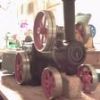
It is a three train flat bed clock made in 1889 by Smiths of Derby, and still maintained by them. The movement is fairly simple, pinwheel escapement, count wheel chime and strike. Each train has a limited number of wheels. All the pinions are lantern, and the bearings are brass bushes, some in iron castings individually mounted on the top and bottom of the bed so depthing should be fairly easy. The bed is one piece cast iron - but I would probably fabricate it from steel.
The real thing is about six feet wide. It beats 3150/hour, and trips the chime train four times for each revolution of the output shaft (closest to the camera on the image above) . Thinking it through I t seems to me that if I made a 1/4 scale version it would beat twice as fast, and if I tripped the chime train twice per rev I would get a clock that looked OK, and kept to time. The motion work behind the dial ( about 20ft above the clock) is driven by a pair of bevel gears.
By halving the ratio of these gears I should be able to get the hands to turn at the right speed. I can't see anything too difficult (apart from having to learn how to cut wheels!!) except possibly the pair of bevel gears that send the output up to the dial and those on the motion work, and the latter could probably use a standard commercial set as they will be non scale and hidden behind the dial. The chime barrel will be fairly fiddly to get right, but in principle should be doable. Before I set to measuring the real thing, counting teeth and planning a bit harder, I thought I would ask on here to see if anyone has done something similar - or if anyone can think of any major gotcha's I might run into. Edited By Peter Cook 6 on 30/10/2021 16:23:31 |
| Bizibilder | 30/10/2021 16:28:11 |
 173 forum posts 8 photos | If you can get hold of a copy of John Wildings "Small Tower clock movement" it gives a full description of the construction of a clock similar to your own ideas. It is £30 from here: Clock Book - Well worth the money (It's on my own list of "projects to do"!) |
| Michael Gilligan | 30/10/2021 17:06:27 |
 23121 forum posts 1360 photos | That looks a wonderful project, Peter [ and significantly more complex/interesting than the Wilding one ] I would think everything is scaleable to 1/4x … except of course for matters of Time [which you have already addressed]. MichaelG. |
| Peter Cook 6 | 30/10/2021 17:35:45 |
| 462 forum posts 113 photos | Thanks Michael, I suspect that as a clock it is actually less complex than the Wilding design in many ways. The trains are simpler, and as far as I can see the clock was a "mass production" design, so the bearing carriers are identical front to back. The great wheels on all three trains are the same, as are all the lantern pinions and the wheels for the chime and strike - so once I have sussed out how to make one - I will be into production, and the second one of anything I make is usually better than the first. And it has the overriding advantage that I can simply have a look at the real thing whenever I get stuck. |
| Michael Gilligan | 30/10/2021 18:43:40 |
23121 forum posts 1360 photos | You might find this interesting, Peter : **LINK** https://richard.burtons.org/2014/11/28/restoring-a-j-smith-and-sons-derby-turret-clock/ His restoration involves some re-creating of parts … to make-good the damage that was done when “unknown” converted it to Electric. MichaelG. |
| duncan webster | 30/10/2021 19:17:44 |
| 5307 forum posts 83 photos | This merits a write up in ME Edited By duncan webster on 30/10/2021 19:18:03 |
| Michael Gilligan | 30/10/2021 22:44:23 |
23121 forum posts 1360 photos | Thanks to the aforementioned blog by Mr Burton … I have located this little gem : **LINK** https://archive.org/details/towerclockhowtom00ferso MichaelG. . Edit: __ and if you browse the available files, you will find a very good .jpg image of the layout Edited By Michael Gilligan on 30/10/2021 22:52:14 |
| JA | 30/10/2021 23:35:34 |
 1605 forum posts 83 photos | Peter This may be a very dumb question but have you approached Smiths of Derby for information? They could be very useful, or not. I used to pass their works, not large, on the way to Derby Tech for about four years, many many years ago. JA |
| Peter Cook 6 | 31/10/2021 12:02:59 |
| 462 forum posts 113 photos | Thank you Michael for the information sources. Plenty to peruse and muse upon in the darkening winter nights. JA - No I haven't ( as yet) approached Smiths. However one of their service engineers is due any month soon to do the annual service on the clock - so I will pick their brains while keeping them company in the tower (H&S you understand!). Having to stop the clock for an hour this morning due to the end of BST, and because the weather was unfit for the walk I usually do to while the time away, I took some basic measurements of the clock to see what I faced. The largest wheels ( the driving gears for the chime & strike trains) are 16" in diameter, so at 1/4 scale they will be 4" - and within the capacity of my Taig - so the project looks possible. However these wheels (2 off) look to have 150+ teeth, and the big wheels (again 2 off) for the fly's plus the time train great wheel are 120+ teeth, so its possible CNC may rear itself up the project list!! Thanks again for the pointers and help. I must get some workshop time to reduce the backlog of projects and clocks needing repair so that I can possibly start on this one. |
| JA | 31/10/2021 12:10:40 |
1605 forum posts 83 photos | Peter Please keep us informed on your thoughts and progress. JA |
| Martin Kyte | 31/10/2021 14:51:57 |
 3445 forum posts 62 photos | The first thing that occurs to me is that the capacity of the barrels is going to be a lot smaller so that the time between winding with be shorter. Similarly the torque available will be less with smaller diameter barrels and correspondingly smaller weights. However with smaller weights you can use thinner wire rope and get more turns on per inch. Non scale weights allows for some fiddle factor too. I think I would be inclined to alter the escapement to suit the shorter pendulum (more pins on the pinwheel) so you get the correct timing at the top end of the clock. I suggest you build the escapement and pendulum first and get that going as a test rig. You can get some idea of the torque you need to power the escapement that way. So long as the ratio's stay the same the wheel diameters can be scaled with impunity. If you are intending an exterior dial then you should allow much more power for driving the hands than for an indoors dial. You have to cope with wind gusts that can stop the clock if the torque is too low. Essentially it starves the escapement of power. The Trinity clock at Cambridge suffers from pidgeons sitting on the hands which make a mess of the accuracy although doesn't actually stop the clock. have fun regards Martin |
| Peter Cook 6 | 31/10/2021 17:21:48 |
| 462 forum posts 113 photos | Thanks Martin, more issues to muse upon. I had not really considered the weight issue. The real clock has 185Kg on the chime train, 110 on the strike and a mere 27Kg on the time train a grand total of 322 Kg hauled up 10 metres twice a week. The Chime and strike are three pulley systems, the time is only two. I think I was hoping to get away with rather less than the 80Kg that comes from dividing by four, but I think some serious math on run times and weights is going to be required. I have a couple of longcase clocks with barrels about 2" in diameter that run for eight days, so if I am careful with pivot quality on the time train I might be OK. A quick calculate suggests that with scale barrels I will need about 2metre of cable for a 24 hour run if I allow it to run at double speed. But getting 80 pins on the pinwheel might be a challenge! Lots to think about. It looks like this will take all the time until my backlog is cleared just thinking about the issues. Thanks again - its the things you didn't know you didn't know that are the most helpful in these forums. PS Michael - While browsing the Burton blogs up popped a link to my clock. Most surprised!! Edited By Peter Cook 6 on 31/10/2021 17:25:17 |
| Martin Kyte | 31/10/2021 18:50:06 |
3445 forum posts 62 photos | I would go with the longest pendulum you can accomodate rather than scale it, that may get you less pins on the pinwheel. Huygens endless rope could be a way to go with the weights and winding. You can arrange for auto wind then. The main thing is to ensure you have enough torque to drive the clock. Reduction in size will help with the friction and you can fit ball races to the bottom end without it showing. What length is the pendulum on the church clock? regards Martin |
| Peter Cook 6 | 31/10/2021 20:49:13 |
| 462 forum posts 113 photos | Thanks Martin. More useful thoughts. At twice speed the great wheel turns once every 1.5 hours. Scale drum is 36mm diameter and 90mm long so 113mm of cable per rev and 16 revs per 24 hours = 1.8metres per day. With 96mm of drum length, 8 days allows 12mm/day of width so max cable thickness is 12/16 or 0.75mm. Thin steel cable @0.6mm has 20Kg breaking strain. 100lb breaking strain fishing line is 0.5mm diameter. Hopefully that sort of pull will do it. However I will as you suggest start with the escapement and experiment. The real pendulum is 1.5m long, so lengthening at scale it is a possibility. I think I am beginning to understand why people build to existing sets of drawings - scaling reality is complicated! |
| bernard towers | 01/11/2021 00:00:47 |
| 1221 forum posts 161 photos | Looks like a great project,I did the wilding clock a couple of years ago, cast the wheels made the cutters and it worked there’s a surprise! |
| Michael Gilligan | 01/11/2021 06:18:47 |
23121 forum posts 1360 photos | Nice work, Bernard … some notes about your casting process would be very interesting. MichaelG. |
| Roger Best | 01/11/2021 09:27:35 |
 406 forum posts 56 photos | Fabulous idea. Such clocks are a bastion of civic life, we have one in our village and I can hear it clearly on a quiet night over half a mile away.. Surely if you quarter scale the weights should be 1/64 ?? Cheers Rog |
| bernard towers | 01/11/2021 22:56:34 |
| 1221 forum posts 161 photos | Michael, The casting was very basic using brand new old stock brass electrical fittings with approx 8%lead added to try to get to cz120 spec. I have to say that the result was brass that machined easily and quietly not with the noise you associate with machining cz121. |
| John Haine | 02/11/2021 07:24:04 |
| 5563 forum posts 322 photos | Though a departure from scale, had you considered a compound pendulum, ie one with mass above the pivot as well as below so it will still beat at the same rate? |
| Michael Gilligan | 02/11/2021 08:17:37 |
23121 forum posts 1360 photos | Posted by bernard towers on 01/11/2021 22:56:34:
Michael, The casting was very basic using brand new old stock brass electrical fittings with approx 8%lead added to try to get to cz120 spec. I have to say that the result was brass that machined easily and quietly not with the noise you associate with machining cz121. . Thanks for that, Bernard Would I be right in assuming that these are open ‘flat’ castings made in sand ? MichaelG. |


Please login to post a reply.
Magazine Locator
Want the latest issue of Model Engineer or Model Engineers' Workshop? Use our magazine locator links to find your nearest stockist!
Sign up to our Newsletter
Sign up to our newsletter and get a free digital issue.
You can unsubscribe at anytime. View our privacy policy at www.mortons.co.uk/privacy
Latest Forum Posts
- *Oct 2023: FORUM MIGRATION TIMELINE*
05/10/2023 07:57:11 - Making ER11 collet chuck
05/10/2023 07:56:24 - What did you do today? 2023
05/10/2023 07:25:01 - Orrery
05/10/2023 06:00:41 - Wera hand-tools
05/10/2023 05:47:07 - New member
05/10/2023 04:40:11 - Problems with external pot on at1 vfd
05/10/2023 00:06:32 - Drain plug
04/10/2023 23:36:17 - digi phase converter for 10 machines.....
04/10/2023 23:13:48 - Winter Storage Of Locomotives
04/10/2023 21:02:11 - More Latest Posts...
- View All Topics
Support Our Partners


Shopping Partners
Subscription Offer

Latest "For Sale" Ads
- Reeves** - Rebuilt Royal Scot by Martin Evans
by John Broughton
£300.00 - BRITANNIA 5" GAUGE James Perrier
by Jon Seabright 1
£2,500.00 - Drill Grinder - for restoration
by Nigel Graham 2
£0.00 - WARCO WM18 MILLING MACHINE
by Alex Chudley
£1,200.00 - MYFORD SUPER 7 LATHE
by Alex Chudley
£2,000.00 - More "For Sale" Ads...
Latest "Wanted" Ads
- D1-3 backplate
by Michael Horley
Price Not Specified - fixed steady for a Colchester bantam mark1 800
by George Jervis
Price Not Specified - lbsc pansy
by JACK SIDEBOTHAM
Price Not Specified - Pratt Burnerd multifit chuck key.
by Tim Riome
Price Not Specified - BANDSAW BLADE WELDER
by HUGH
Price Not Specified - More "Wanted" Ads...
Get In Touch!
Do you want to contact the Model Engineer and Model Engineers' Workshop team?
You can contact us by phone, mail or email about the magazines including becoming a contributor, submitting reader's letters or making queries about articles. You can also get in touch about this website, advertising or other general issues.
Click THIS LINK for full contact details.
For subscription issues please see THIS LINK.
Digital Back Issues


Donate

 Register
 Log-in
Model Engineer Magazine
- Percival Marshall
- M.E. History
- LittleLEC
- M.E. Clock

ME Workshop
- An Adcock
- & Shipley
- Horizontal
- Mill

Subscribe Now
- Great savings
- Delivered to your door

Pre-order your copy!
- Delivered to your doorstep!
- Free UK delivery!
All Forum Topics > Clocks and Scientific Instruments > A Tower Clock project