Forum sponsored by:

5” Rotary Table/Tailstock/Chuck Kit Info/Questions
| Dr_GMJN | 01/09/2021 19:54:22 |
 1602 forum posts | All, I’ve got a couple of threads running where rotary tables have been mentioned (ok, mainly by me). One thing to put to bed straight away: I don’t really *need* one, but it would be handy for some jobs, and - primarily - good fun to play with. Ive got an SX2P mill, and a 5” table was suggested as a good size for that. Soba was a brand mentioned, and one of the usuals has a set including table, tailstock, 4-jaw chuck and dividing plates. Cost is about £340 from Chronos, delivered. I understand that quality could be acceptable, but chances are it might need some fettling. I watched a review video, and it seemed as expected. The drawings show an overall height of about 6” when the Chuck is fitted vertically, which gives little room for a part plus tooling. The head would be near (or exceed) maximum travel for any useful work I think. Questions are in general: Does anyone have experience of this set? Is it any good? Is the 4-jaw only much use for horizontal work? Is there a ‘rotary table 101’, for example what’s the correct way of centering the table under the spindle, and when using the 4-jaw chuck how do you subsequently centre the work in that? Any advice gratefully accepted. Thanks.
|
| Clive Brown 1 | 01/09/2021 20:14:52 |
| 1050 forum posts 56 photos | The chuck is self-centering. |
| JasonB | 01/09/2021 20:17:42 |
 25215 forum posts 3105 photos 1 articles | I've had the 6" Soba and all the bits from Chronos for 10 years or more and it's done all I've asked of it so hopefully the 5" will be similar. Mine came with a 3 jaw and that gets used equally in both vertical and horizontal modes the 4-jaw SC would be similar. Also have a flange mount ER32 that gets used sometimes as it's a bit shorter and also allows the spindle collet to get closer to small work when table is vertical.
|
| Richard Millington | 01/09/2021 21:10:58 |
| 101 forum posts 9 photos | To centre my rotary table I have a centered plug which fits into the rotary table centre. This allows put a centre into the mill spindle and just run it down to the rotary table to centre it to the spindle then bolt it to the mill table. |
| Andrew Johnston | 01/09/2021 21:31:40 |
 7061 forum posts 719 photos | When I bought my (secondhand) rotary table I also bought a small import 3-jaw chuck. I've never fitted it and not missed it, so I never will fit it. I mount work direct on the table. Andrew |
| Dr_GMJN | 01/09/2021 21:47:49 |
1602 forum posts | Thanks all I’d missed the SC bit about the chuck. Should have read more carefully. Andrew - the first part I’d use it for is the small (c.30 mm) diameter aluminium output shaft blank for my son’s rc car (as per earlier thread) The Chuck would seem the obvious choice to hold it, but the height restriction could be an issue. What would be the best way of centering and holding a piece like that direct to the table? Make a temporary base plate and screw the bar vertically to that, then clamp the plate to the rotary table? Or something like that? Cheers.
|
| Dr_GMJN | 01/09/2021 21:51:09 |
1602 forum posts | Posted by Richard Millington on 01/09/2021 21:10:58:
To centre my rotary table I have a centered plug which fits into the rotary table centre. This allows put a centre into the mill spindle and just run it down to the rotary table to centre it to the spindle then bolt it to the mill table. I was wondering if something like that is accurate enough. Sounds straightforward. I guess you could also turn and drill a tight fitting centre plug, then align the table so the drill presses straight into the hole? |
| Paul Lousick | 02/09/2021 00:38:06 |
| 2276 forum posts 801 photos | As already mentioned, using a centre in the mill to locate in a hole in the RT (or vice versa) is a quick set-up method for most work. For a more accurate set-up, mount a dial indicator on the mill spindle and use it to locate on the morse taper of the rotary table spindle. (or the machined recess on the end of some RT's). Carefully turn the mill spindle by hand to achieve zero movement of the indicator. Bolt down the RT and check again to see if it has not moved. Then attach the 4-jaw chuck and use the dial indicator to position the work. (4-jaw chuck could be attached prior, if there is access to locate on the RT morse taper for the initial set up) Paul |
| Robin Graham | 02/09/2021 01:16:12 |
| 1089 forum posts 345 photos | I have a 6" Vertex RT which I use with my WM14 mill - about the same size as the SX2, perhaps a bit smaller:
That's obviously an - ahem - suboptimal setup, but shows what can be done in the way of fitting quarts into pint pots. The work was ~1" diameter and the tool mounted in an ER25 collet chuck. I didn't have problems with headroom - it was the size of the table which was problematic. Anyhow it worked:
The chuck is a SC 3-jaw, which lives pretty much permanently on the RT. It works for most of what I do. I can't see what advantage a 4 jaw SC would bring for RT work, but maybe I'm missing something. The RT has a 2MT bore and I centered the chuck by turning down a 2MT soft arbor to fit the back end of the parallel chuck bore. This has the disadvantage that it blocks the RT bore, but on the plus side it's proved pretty accurate - better than 0.03mm TIR . It's a good (Rohm) chuck though, which may have something to do with it. Robin.
|
| JasonB | 02/09/2021 07:34:06 |
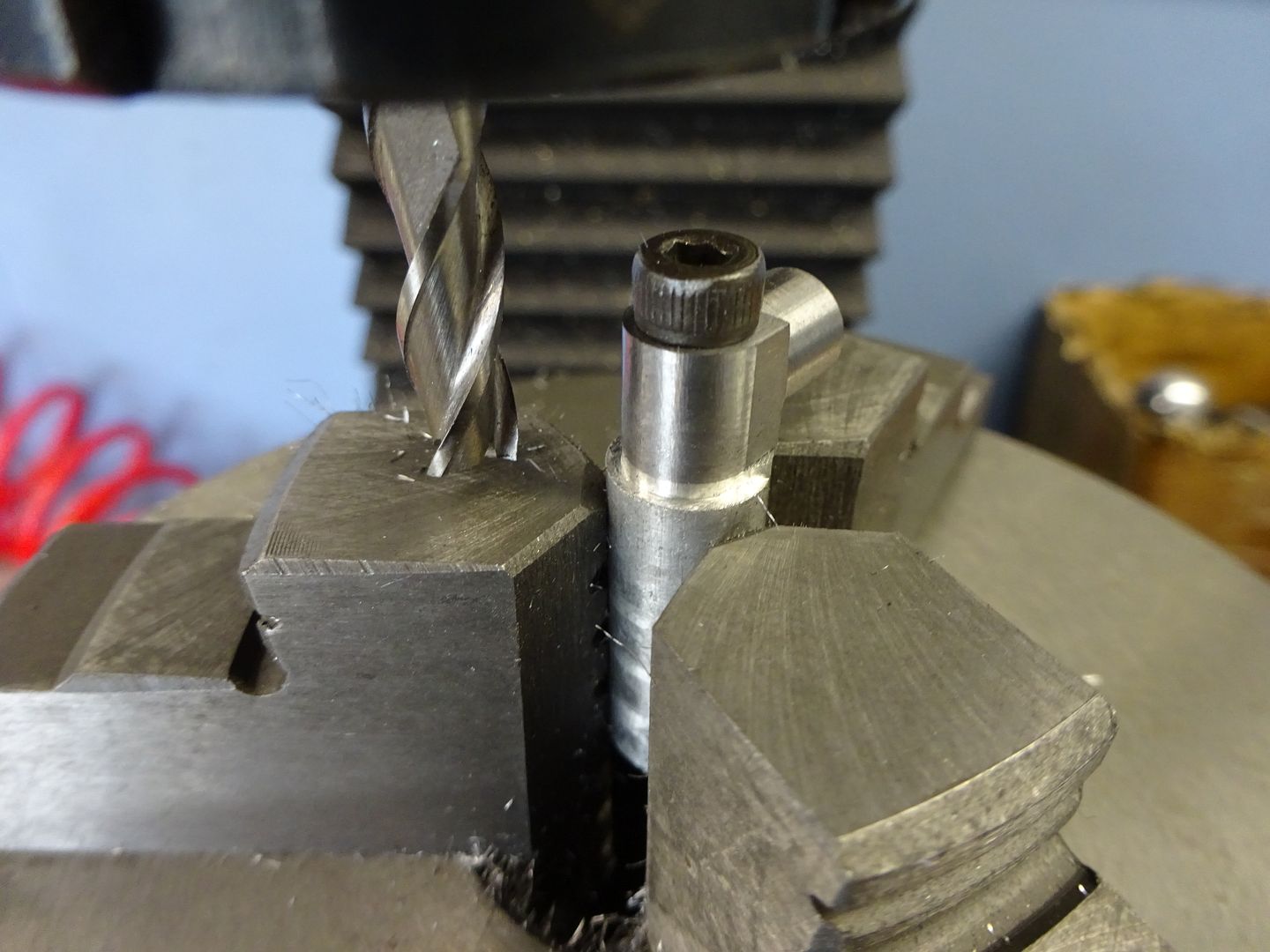
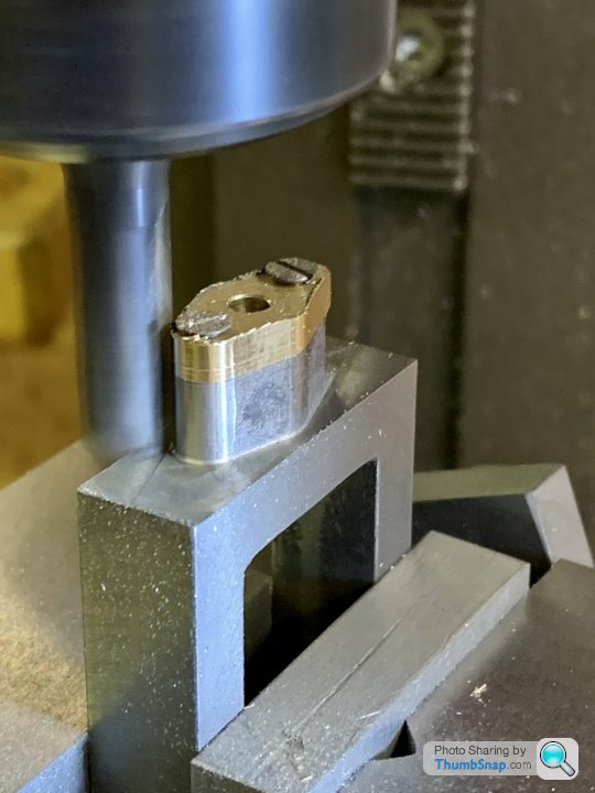
25215 forum posts 3105 photos 1 articles | I suppose a lot depends on the part or parts you are working on as well as what other tooling you have as to what's the better method to use for holding work on the R/T. On thing mine get used for quite a lot is rounding over the ends of rods etc, in fact the 6" ARC one tends to stay fixed to the SX2.7 most of the time with it's 3-jaw so it's ready to go for just this type of work. Looking back through the photos of my Victoria build that's the only thing the R/T was used for and all done with the 3-jaw. Over the years I have built up a fair number of simple arbors which get reused or it's not hard to knock up another and these just go into the chuck and the work screws to those. Not sure I would want to try clamping this 1/4" sq x 3/8" long part direct to the table and still be able to get at it will a 6mm cutter and not hit any clamps
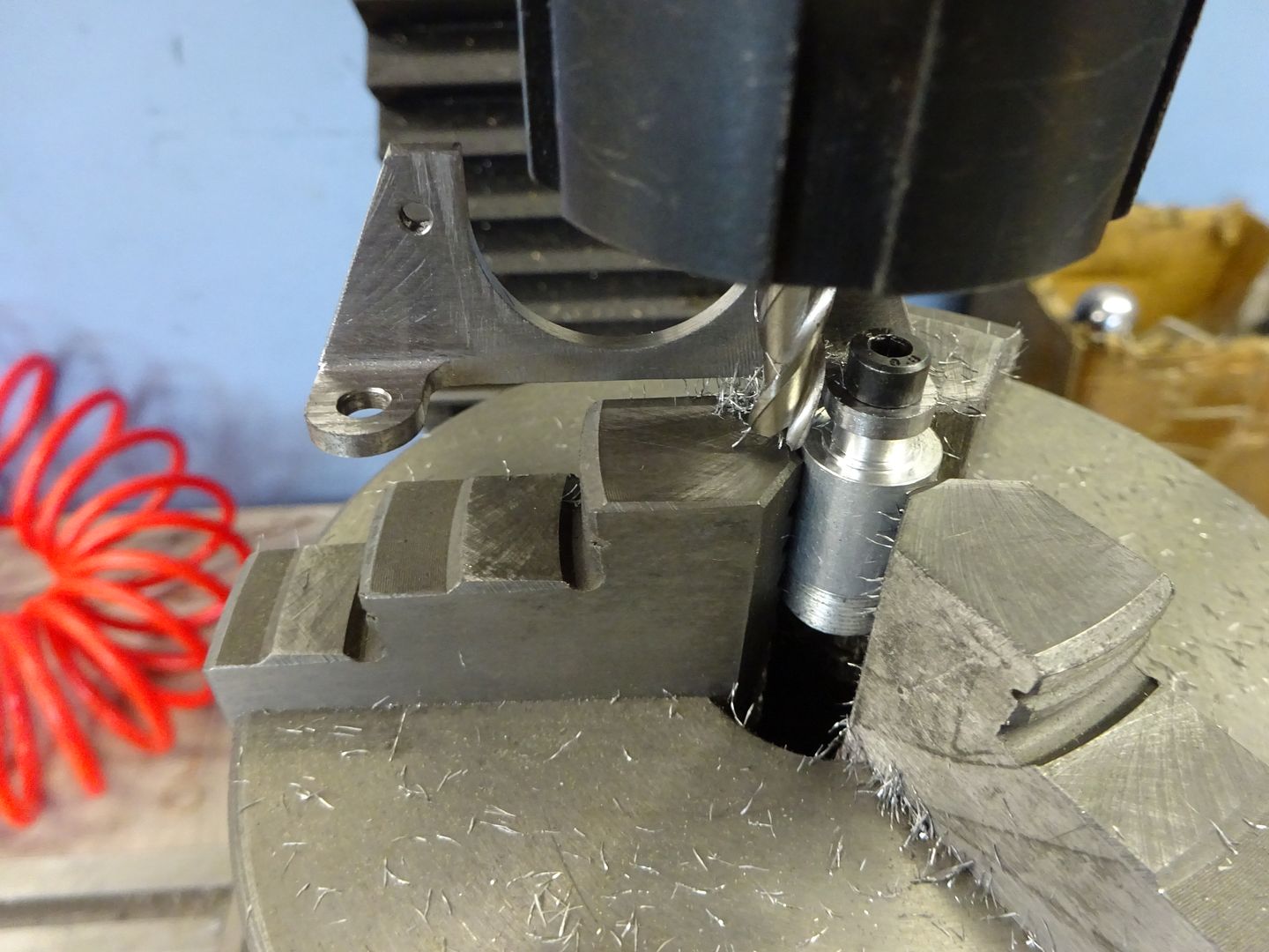
The Cylinder legs may have been easier to clamp being larger but still quicker to just screw to the arbor
As you don't have any form of indexer like a 5C spin indexer you will end up using the R/T to cut square or hex shapes onto small parts which will again be quick and easy to hold in a chuck or collet fixed to the table
|
| Dr_GMJN | 02/09/2021 08:20:09 |
1602 forum posts | Thanks all. I think I'll get one ordered and have a play. Ron thinks that particular one is OK, so that's good enough for me. |
| Andrew Johnston | 02/09/2021 11:05:06 |
7061 forum posts 719 photos | Posted by Dr_GMJN on 01/09/2021 21:47:49:
......the first part I’d use it for is the small (c.30 mm) diameter aluminium output shaft blank for my son’s rc car (as per earlier thread) The Chuck would seem the obvious choice to hold it, but the height restriction could be an issue. What would be the best way of centering and holding a piece like that direct to the table? Make a temporary base plate and screw the bar vertically to that, then clamp the plate to the rotary table? Or something like that? I'd concede that a chuck might be the simplest solution, but not necessarily the most accurate. My rotary table has a 1" parallel hole in the centre, which is way more useful than a Morse taper. So I'd make a 1" spigot with a flange for clamping to the table and a recess to locate the work. There would also be a hole for a screw into the part to be machined. Andrew |
| JasonB | 02/09/2021 11:21:43 |
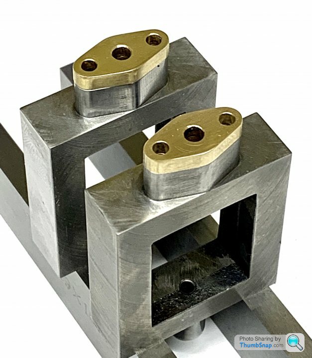
25215 forum posts 3105 photos 1 articles | Unfortunately said screw would get in the way of machining with the 1.5mm dia cutter so back to doing what suits the job in hand.
If you could not get the chuck in then a 5mm pin held in your collet chuck and lowered into the central hole would locate the part and a couple of small clamps will hold it down by the flange. Zero DRO before raising head and changing to the cutter. Though as I said it could be done without a rotary table too. Edited By JasonB on 02/09/2021 11:24:44 |
| SillyOldDuffer | 02/09/2021 11:21:52 |
| 10668 forum posts 2415 photos | Posted by Dr_GMJN on 02/09/2021 08:20:09:
... Ron thinks that particular one is OK, so that's good enough for me. My advice is not to get wrapped round the axle worrying about the quality of hobby tools. If the best possible rotary is really needed (and I suggest it's not), then buy an industrial model. It will cost a few thousand pounds, and although it will be somewhat more robust, don't expect it to be bullet proof. Many a well-made rotary table has been wrecked hacking out big wheels for model traction engines! Most hobby rotary tables are of the HV6 design. A worm drives a cogged wheel and turns the table on a simple plain bearing. Though obviously made down to a price, they're reasonably accurate and sufficiently sturdy for most amateur purposes. They're aren't high-technology, nowhere near as difficult to make as a computer hard disc. The buying strategy for this class of affordable tool is quite different from the good old days. Until about 1960, tools were so expensive it paid to get the best one could afford in hope it would last a lifetime. Not a good idea to buy cheap back then, because there was a sharp divide between well-made and cheap and nasty. There were brand names that could be relied on, so what grandad said about them was worth listening too. This world has pretty much gone. Today the world is flooded with mid-range tools, affordable rather than excellent. Not intended to last forever, they are nonetheless generally acceptable for the light duty found in typical hobby workshops. Many products come from similar anonymous factories, and are rebranded by a local seller. But be aware that some versions are too cheap, or customer returns, or manufacturer rejects. The customer probably has no idea who made the item, or even which country or countries it came from. And for this class of kit, it rarely matters. The customer isn't looking for 'quality', he's after 'value for money' and 'fit for purpose'. So, rather than spend ages looking for a magical brand-name, I suggest a more appropriate procurement strategy is to:
'It won't last' scream the old-school! True, nothing does. The point is, at the moment, hobby-market Rotary Tables and the like don't have to. Main exception to value for money purchasing is bragging rights: you can't boast about Far Eastern hobby equipment! Don't care myself because tools only have to do what I want of them, and that doesn't include impressing the neighbours! Dave |
| Andrew Johnston | 02/09/2021 11:34:08 |
7061 forum posts 719 photos | Posted by JasonB on 02/09/2021 11:21:43:
Unfortunately said screw would get in the way of machining with the 1.5mm dia cutter.......................... Oh dear, it seemed obvious that the screw would go in from the bottom of the work so I didn't specify same. Andrew |
| Howard Lewis | 02/09/2021 13:01:39 |
| 7227 forum posts 21 photos | If it possible to mount the work vertically in the vice or chuck, to produce a square. you only have to run the cutter along each side, in turn, to remove enough metal to leave a square of the size that you want. To align the Tailstock with the R T when used in horizontal mode, my method is. Obtain a blank arbor with taper to fit the bore in the R T, and carefully bore it to be a snug fit on the barrel of the Tailstock. (As indication of the fit, mine goes "pop" when the arbor is pulled off the barrel ) My Tailstock is aligned to the T slot by means of stepped dowels, so the R T is aligned by fitting the Arbor into the R T, with the securing bolts slack. For the first time alignment, the clamp bolts for the vertical position of the tailstock barrel are left slack. In this way, with the R T in a suitable position on the table, the Tailstock is clamped to the table, so that the Tailstock barrel can be inserted into the bored arbor. For the first time alignment, by leaving the vertical clamps for the Tailstock barrel loose, as the R T is aligned with the Tailstock, the Tailstock barrel is now aligned in the vertical plane, with the R T., and the clamp bolts can be remain tight and untouched for the future. The Tailstock barrel locates the R T.so that it can be clamped to the table. The Tailstock can then be repositioned wherever is suitable along that T slot, for the work in hand. Howard |
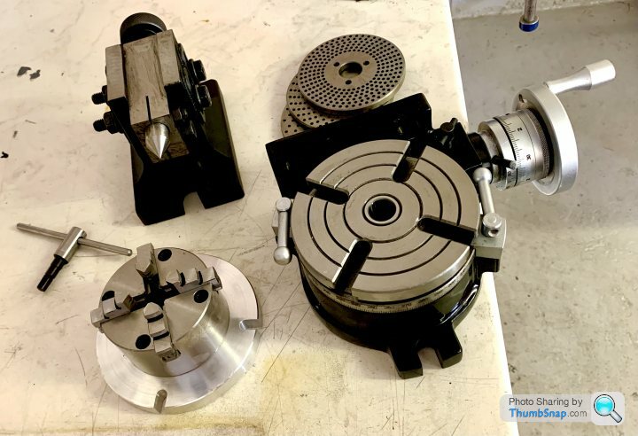
| Dr_GMJN | 19/09/2021 22:33:19 |
1602 forum posts | Thanks everyone. Just to wrap the thread up, I got the 5” rotary table as suggested: |
| Dr_GMJN | 19/09/2021 22:42:27 |
1602 forum posts |
One other thing, the height of the R/T plus chuck(or vice) plus a part adds up. It’s quite a stack under the SX2P: Oh, and I also milled the main casting to make the lock-down nut mating surface in the vertical pocket (visible above) horizontal. This is noted in other reviews. I also skimmed the surfaces of the other lugs just as a precaution. Very quick and easy to do in the end. Edited By Dr_GMJN on 19/09/2021 22:51:07 |
| Ron Laden | 20/09/2021 09:52:08 |
 2320 forum posts 452 photos | Pleased your generally happy with the Soba 5 inch table it should serve you well. I must have been lucky with mine I have 1.5 minutes backlash at the handwheel and 0.0015" at the table edge. In a full 360 degree rotation I have a couple of spots each about 15 degrees worth where it goes a tad light but hardly noticeable. Don't forget you can gain around 40mm in Z if you use finger collets against using the collet chuck. I have a 6mm and 10mm which take most of my regular cutters. I mainly use the collet chuck but if you have a tall job plus a table mounted vice or chuck it could make all the difference to fitting the job and tooling in. The 40MM extra on mine is based on my finger collets against the collet chuck both from ARC. Ron Edited By Ron Laden on 20/09/2021 09:53:53 |
| Howard Lewis | 20/09/2021 17:29:17 |
| 7227 forum posts 21 photos | When you come to use the R T in the Vertical mode (Table face vertical, axis horizontal )) you will need yto align the R T and the Tailstock. My Tailstock has tappings for a key or dowels. Because my T slots differed in width from the keyway on the Tailstock, I made up two stepped dowels. One end is tight fit in the Tailstock keyway, and the other in the T slot of the Mill table. So that is the Tailstock aligned to the Mill Table. It now needs to be be aligned vertically, with the R T. The RT also needs to be aligned with the axis of the Tailstock, along and across the Mill table.. These can both be done at the same time. With an arbor (In my case 2MT ) bore the blank end to a really snug fit around the OD of the Tailstock centre. Position the R T, loosely, on the Mill table so that it roughly aligns with the Tailstock, in the place where you wish to use it, with the 2MT alignment arbor in place... Slacken the clamps for the vertical position of the Tailstock centre Enter the Tailstock Centre into the bore of the 2MT alignment arbor., and clamp the Tailstock to the Mill table. The dowels will have aligned the Tailstock. The Centre barrel, being snugly located in the 2MT arbor will have aligned the Tailstock barrel vertically; and the R T along and across the Mill table, so both can be clamped. Once the Tailstock centre barrel has been aligned, it is set up and should not need to be reset. It can be used, with the 2MT arbor to align the R T on the Mill table in the future. HTH Howard (Anyone know a good typist? ) Edited By Howard Lewis on 20/09/2021 17:36:13 |


Please login to post a reply.
Magazine Locator
Want the latest issue of Model Engineer or Model Engineers' Workshop? Use our magazine locator links to find your nearest stockist!
Sign up to our Newsletter
Sign up to our newsletter and get a free digital issue.
You can unsubscribe at anytime. View our privacy policy at www.mortons.co.uk/privacy
Latest Forum Posts
- *Oct 2023: FORUM MIGRATION TIMELINE*
05/10/2023 07:57:11 - Making ER11 collet chuck
05/10/2023 07:56:24 - What did you do today? 2023
05/10/2023 07:25:01 - Orrery
05/10/2023 06:00:41 - Wera hand-tools
05/10/2023 05:47:07 - New member
05/10/2023 04:40:11 - Problems with external pot on at1 vfd
05/10/2023 00:06:32 - Drain plug
04/10/2023 23:36:17 - digi phase converter for 10 machines.....
04/10/2023 23:13:48 - Winter Storage Of Locomotives
04/10/2023 21:02:11 - More Latest Posts...
- View All Topics
Support Our Partners


Shopping Partners
Subscription Offer

Latest "For Sale" Ads
- Reeves** - Rebuilt Royal Scot by Martin Evans
by John Broughton
£300.00 - BRITANNIA 5" GAUGE James Perrier
by Jon Seabright 1
£2,500.00 - Drill Grinder - for restoration
by Nigel Graham 2
£0.00 - WARCO WM18 MILLING MACHINE
by Alex Chudley
£1,200.00 - MYFORD SUPER 7 LATHE
by Alex Chudley
£2,000.00 - More "For Sale" Ads...
Latest "Wanted" Ads
- D1-3 backplate
by Michael Horley
Price Not Specified - fixed steady for a Colchester bantam mark1 800
by George Jervis
Price Not Specified - lbsc pansy
by JACK SIDEBOTHAM
Price Not Specified - Pratt Burnerd multifit chuck key.
by Tim Riome
Price Not Specified - BANDSAW BLADE WELDER
by HUGH
Price Not Specified - More "Wanted" Ads...
Get In Touch!
Do you want to contact the Model Engineer and Model Engineers' Workshop team?
You can contact us by phone, mail or email about the magazines including becoming a contributor, submitting reader's letters or making queries about articles. You can also get in touch about this website, advertising or other general issues.
Click THIS LINK for full contact details.
For subscription issues please see THIS LINK.
Digital Back Issues


Donate

 Register
 Log-in
Model Engineer Magazine
- Percival Marshall
- M.E. History
- LittleLEC
- M.E. Clock

ME Workshop
- An Adcock
- & Shipley
- Horizontal
- Mill

Subscribe Now
- Great savings
- Delivered to your door

Pre-order your copy!
- Delivered to your doorstep!
- Free UK delivery!
All Forum Topics > Workshop Tools and Tooling > 5” Rotary Table/Tailstock/Chuck Kit Info/Questions