Forum sponsored by:

HSS/Tungsten Tool Honing Machine
| Graham Meek | 17/06/2020 12:10:13 |
| 714 forum posts 414 photos |
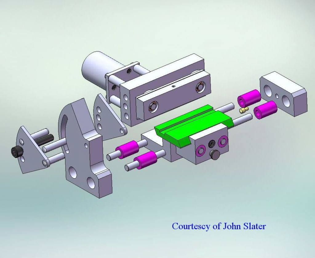
I have just started the manufacture of a Project which has been 8 years in the design stage. Certain features which I wanted to include in the machine were proving difficult to fit into the space available, but I think I have done it now, thanks to help from John Slater. There have been many times I have needed to put a very fine radius on a tool, and while I have managed to do this free hand it would have been so much easier with a dedicated piece of tooling. Which presented the tool to the Hone in a repeatable manner. The recent post on Boring Bars brought out a piece of information from the Sandvik web site concerning the tip radius on a boring tool, with regards to the depth of cut taken. Sandvik recommend that this radius should never be larger than the depth of cut. This has spurred me into getting this machine up and running if only to prove the above works in practice. I hope over the coming months to keep you informed of my progress. Regards Gray, |
| Michael Gilligan | 17/06/2020 13:36:08 |
 23121 forum posts 1360 photos | Looks very interesting, and very useful, Gray After 8 years in your capable mind ... The design should be spot-on. Thanks MichaelG. |
| Graham Meek | 18/06/2020 09:26:03 |
| 714 forum posts 414 photos |
Thanks Michael, but I do not always get things right, no one ever gets to see my scrap box. The break through, if I can call it that, came when I thought about having separate dedicated tables for each function. The radius attachment needs a setting fixture and this too took some simplifying, the last thing I wanted was a very complex tool. To set a radius accurately merely requires the use of the appropriate sized feeler blade, but more on that again. Regards Gray, Edited By Graham Meek on 18/06/2020 09:26:50 Edited By Graham Meek on 18/06/2020 09:28:22 |
| Graham Meek | 04/08/2020 16:47:07 |
| 714 forum posts 414 photos |
For those who may be following this post, here are the main items of the Honing Machine finished. The cranks and the interchangeable tables are next on the list. Hopefully the next photograph in a few days will show the main parts assembled. Regards Gray, |
| Raymond Anderson | 04/08/2020 17:38:55 |
 785 forum posts 152 photos | Superb. |
| Steve King 5 | 04/08/2020 18:38:56 |
| 86 forum posts 95 photos | Im followingbthis with great interest. |
| Graham Meek | 08/08/2020 11:08:56 |
| 714 forum posts 414 photos | Thanks Raymond and Steve for the encouragement. I regret to say the hot weather has slowed my progress, but I have managed to get the Crankshafts made.
The parts are Mild Steel web and Silver Steel shafts. They are Press fits into the web and are clinched with a ball bearing in the hole to make sure they stay put. Regards Gray, |
| ega | 08/08/2020 17:03:19 |
| 2805 forum posts 219 photos | Posted by Graham Meek on 08/08/2020 11:08:56:...
The parts are Mild Steel web and Silver Steel shafts. They are Press fits into the web and are clinched with a ball bearing in the hole to make sure they stay put. ...The ball bearing method is new to me. Is the idea that the shaft end is slightly expanded by being forced on to the ball at the bottom of the hole? |
| Michael Gilligan | 08/08/2020 18:40:38 |
23121 forum posts 1360 photos | Posted by ega on 08/08/2020 17:03:19:
Posted by Graham Meek on 08/08/2020 11:08:56:...
The parts are Mild Steel web and Silver Steel shafts. They are Press fits into the web and are clinched with a ball bearing in the hole to make sure they stay put. ...The ball bearing method is new to me. Is the idea that the shaft end is slightly expanded by being forced on to the ball at the bottom of the hole? . Mmm ... New to me, too That would, I suppose, be equivalent to ‘fox-wedging’ in woodwork MichaelG. |
| Howard Lewis | 08/08/2020 18:53:46 |
| 7227 forum posts 21 photos | As usual, beautiful workmanship! Presumably, the ball bearing is pressed into a bore, in the shaft, causing it to expand and become an interference fit? Howard |
| Graham Meek | 08/08/2020 19:05:43 |
| 714 forum posts 414 photos | The holes in the ends of crank-pin and the crankshaft are such that they leave a 0.75 wall thickness around each journal. These holes are only about 2 mm deep. Both holes in the web piece are countersunk 90 degrees by 0.25 wide. In the case of the crank-pin with its 4 mm hole, a 4.75 mm or 3/16" ball bearing is placed on in the hole and using an arbour press the ball bearing is pressed into the hole. The action of the ball is to displace material from the 0.75 mm thick wall into the countersink, in essence riveting the crank-pin int the web. Using a press allows the operator to feel the material being displaced. Once this has happened no further pressure is needed. The beauty of this method is that by using an undersize drill compared to the crank-pin hole in the web. It is possible to easily remove the pin as the initial hole automatically centralises the drill. It is only necessary to drill to the initial 2 mm depth. In doing this the pressure on clinch is reduced and the pin can be pressed out. This of course would only need to be done if a replacement journal is needed due to wear. Thus saving having to remake the whole crankshaft. The same goes for the main crankshaft journal itself. Regards Gray, |
| Graham Meek | 01/09/2020 12:59:00 |
| 714 forum posts 414 photos | I had hoped to take a few more photograph today of the Honing Machine, unfortunately the camera batteries decided they needed recharging, so what I was hoping to show today will have to wait.
Here is the Basic machine assembled. The graduated knob on the carriage is for an adjustable stop. The machine has a fixed stop for use when the Radius Attachment is fitted. The adjustable stop allows the extra 0.025 mm or 0.001" to be taken off if desired. As the graduations are 1 mm apart subdividing a division to take less off is easily achievable. The size of tool bit covered by this machine is 0 to 8 mm, larger tools will be outside the sweep of the stone at the lowest point. As can be seen the machine has been in use and has met the requirements of the design. It has also proved to be more versatile than was expected at the design stage. Some more photographs and a more detailed account to follow. Regards Gray, Edited By Graham Meek on 01/09/2020 13:01:08 |
| Graham Meek | 15/09/2020 14:55:40 |
| 714 forum posts 414 photos | As promised a few days back here are some more shots of the Lathe Tool Honing Machine,
This view differs from the previous one in that a Guard has been added to the Rt hand side. With the stone rotating clockwise there was a distinct pinch hazard.
This second view shows several things, First is the Spring loading that automatically retracts the table and also automatically locates the interchangeable tables in position for locking. The nature of the clamping mechanism means the complete table with the tool still set up can be removed for closer inspection with no loss of positional settings. Secondly is the two position Deadstop. The primary use of the deadstop is when doing radii with the additional table, (more on that later). It also stops any collision between the edge of the table and the Slip stone.
This view shows the Deadstop in position 2, the hole in the stop allows the table to be advanced by a measured amount past the datum position by using the adjustable stop. The graduations on the collar of the adjustable stop can be seen in the first photograph. This collar is only graduated with 10 of the full compliment of 40 divisions as each division is 0.025 mm or 0.001". I could not foresee a need for removing 1 mm with a hone.
A Rear view of the machine showing the drive to the two cranks. The belt is kept in check by a cutout in one of the Motor support pillars so no washers are needed on the pulleys. The graduations on the degree scale can be seen in this view.
This view shows the second table in position for doing the radii, but as yet not fully machined. The felt tip marker traces out a semicircular cut-out to take the tool bit holder. The details of which will be posted soon. Regards Gray, Edited By Graham Meek on 15/09/2020 14:57:15 |
| Michael Gilligan | 15/09/2020 16:41:36 |
23121 forum posts 1360 photos | That’s got real class MichaelG. |
| Martin W | 15/09/2020 17:34:05 |
| 940 forum posts 30 photos | That's an elegant design and the workmanship is brilliant. It's one of those pieces of equipment that 'looks right cause it is right'. Mightily envious of the quality of work that you have achieved. Martin Edited By Martin W on 15/09/2020 17:34:35 |
| Graham Meek | 16/09/2020 11:44:14 |
| 714 forum posts 414 photos | Thank you both for your kind words. I blame my apprenticeship with the Dowty Group as regards having to get everything right. Being part of the Aircraft Industry it had to be right, there are no lay-by's at 40.000 feet. Still their training stood me in good stead as a Toolmaker for 30+ years. Then later getting things right, and the education paid dividends while working for the Oncology Workshops at Cheltenham. Where we would see the effect of our work on patients. Regards Gray, |
| Graham Meek | 17/09/2020 11:35:00 |
| 714 forum posts 414 photos | By way of introducing the next phase of the build. This is the separate table that is used to form the Radii on the tools. The centre for the table and sector radius is the face of the slip stone, or hone.
This shows the Fixture parts for setting the radius. I will leave the setting of this fixture until I have finished the fixture. A picture will save me a thousand words describing how the fixture is used. Suffice to say this fixture automatically sets the tool at the correct radius and centralises it in one go. Regards Gray, |
| Circlip | 17/09/2020 11:52:56 |
| 1723 forum posts | Hope you haven't used what looks like Aluminium for most parts Graham? At one of the ME exhibitions the "Purists downgraded the "Commutator skimming Lathe for model car motors" entered by a Youf because he hadn't used the "Correct" material in its construction. ie Aluminium instead of Cast Iron. If yours is "Incorrect", S*d the judges, it looks fantastic. Regards Ian. Edit, - Next years "JS" award???? Nother edit, It would have cost a lot of money to buy the "Correct" machine to spin rivet the ball bearing operation in industry. Edited By Circlip on 17/09/2020 11:54:32 Edited By Circlip on 17/09/2020 12:12:08 |
| Graham Meek | 17/09/2020 16:08:42 |
| 714 forum posts 414 photos | Hi Ian, They say beauty is in the eye of the beholder, in my book Aluminium looks good and is more than adequate for the job in hand. Plus it is a darn site cleaner to machine than Cast Iron, as well as being kinder on the tooling and the machines. If the "Purist" want to change things to suit themselves that is OK by me. In fact I am happy when someone takes one of my designs and modifies it to suit their needs. As regards exhibitions I only visit, never enter, so I won't have to worry about winning, or not winning anything. The Riveting technique is one I have used for a number of years. It is another technique picked up in the Training School when we made all our own kit. By using a bearing ball the material will flow far easier due to the excellent surface finish on the ball. Whilst the use of an Arbor Press to do the operation allows the operator to feel the material give during the clinching and then go solid when it is fully home. The cost of one bearing ball is peanuts compared to spin rivet tooling. Regards Gray, |
| Neil Wyatt | 17/09/2020 16:34:53 |
 19226 forum posts 749 photos 86 articles | Looks very nice Graham. Neil |


.jpg")
.jpg")
Please login to post a reply.
Magazine Locator
Want the latest issue of Model Engineer or Model Engineers' Workshop? Use our magazine locator links to find your nearest stockist!
Sign up to our Newsletter
Sign up to our newsletter and get a free digital issue.
You can unsubscribe at anytime. View our privacy policy at www.mortons.co.uk/privacy
Latest Forum Posts
- hemingway ball turner
04/07/2025 14:40:26 - *Oct 2023: FORUM MIGRATION TIMELINE*
05/10/2023 07:57:11 - Making ER11 collet chuck
05/10/2023 07:56:24 - What did you do today? 2023
05/10/2023 07:25:01 - Orrery
05/10/2023 06:00:41 - Wera hand-tools
05/10/2023 05:47:07 - New member
05/10/2023 04:40:11 - Problems with external pot on at1 vfd
05/10/2023 00:06:32 - Drain plug
04/10/2023 23:36:17 - digi phase converter for 10 machines.....
04/10/2023 23:13:48 - More Latest Posts...
- View All Topics
Support Our Partners


Shopping Partners
Subscription Offer

Latest "For Sale" Ads
- Reeves** - Rebuilt Royal Scot by Martin Evans
by John Broughton
£300.00 - BRITANNIA 5" GAUGE James Perrier
by Jon Seabright 1
£2,500.00 - Drill Grinder - for restoration
by Nigel Graham 2
£0.00 - WARCO WM18 MILLING MACHINE
by Alex Chudley
£1,200.00 - MYFORD SUPER 7 LATHE
by Alex Chudley
£2,000.00 - More "For Sale" Ads...
Latest "Wanted" Ads
- D1-3 backplate
by Michael Horley
Price Not Specified - fixed steady for a Colchester bantam mark1 800
by George Jervis
Price Not Specified - lbsc pansy
by JACK SIDEBOTHAM
Price Not Specified - Pratt Burnerd multifit chuck key.
by Tim Riome
Price Not Specified - BANDSAW BLADE WELDER
by HUGH
Price Not Specified - More "Wanted" Ads...
Get In Touch!
Do you want to contact the Model Engineer and Model Engineers' Workshop team?
You can contact us by phone, mail or email about the magazines including becoming a contributor, submitting reader's letters or making queries about articles. You can also get in touch about this website, advertising or other general issues.
Click THIS LINK for full contact details.
For subscription issues please see THIS LINK.
Digital Back Issues


Donate

 Register
 Log-in
Model Engineer Magazine
- Percival Marshall
- M.E. History
- LittleLEC
- M.E. Clock

ME Workshop
- An Adcock
- & Shipley
- Horizontal
- Mill

Subscribe Now
- Great savings
- Delivered to your door

Pre-order your copy!
- Delivered to your doorstep!
- Free UK delivery!
All Forum Topics > Manual machine tools > HSS/Tungsten Tool Honing Machine