Forum sponsored by:

CMD10/SeigX1 query
downfeed lock?
| Anthony Knights | 30/04/2020 10:21:54 |
| 681 forum posts 260 photos |
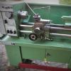
In the photo, I have marked two sets of adjustments and am curious to know if either of them is the proper lock for the downfeed. No1 is a plate with slotted holes and an adjuster screw which would open/close the slit. I adjusted this once when the machine was quite new, to remove a slight bit of play in the quill. I have seen some modification sites where a lever has been added to the screw to use as a lock. This seems wrong to me. No2 is a 10mm hex socket screw with a washer and locknut. When the lock nut is released it is possible to turn the screw almost 1/2 a turn in either direction before it stops. at this point the down feed is locked. The screw is not even shown in the manual that came from Clarke. An on-line manual shows it as an adjuster screw in the exploded diagram, but there is no mention of it in the user instructions. I would just like to know if it's OK to use this as a lock or would I likely to cause some damage. Hopefully someone will know. |
| Tomfilery | 30/04/2020 10:50:32 |
| 144 forum posts 4 photos | Anthony, I don't have the Clarke, but do have an Axminster Micromill, which is basically the same machine. Mine doesn't have the plate with slotted holes, but does have the allen screw screw you have labelled "1" and it is this which is definitely the quill lock! I replaced the allen screw with a handle, on mine. The other socket screw, with locknut, is set to minimise the play on the quill I believe - the screw bears in a slot which runs down the length of the quill, hence why it locks the quill when tightened. I'd use the other one as a lock, if I were you. Hope this helps. Regards Tom |
| Martin Connelly | 30/04/2020 10:59:48 |
 2549 forum posts 235 photos | Number 2 is probably a peg in the slot to stop rotation of the spindle sleeve and everything attached to it. A small amount of peg rotation may act as an adjuster to minimise rotation but still allow movement up and down. Plate item 1 looks to be a spacer for mounting the chuck guard on judging by the photo on the Machinemart web site. Screw item 1 as Tom said. Martin C Ps on parts list item 2 is 144, 145, 146. Badly drawn assembly diagram. Edited By Martin Connelly on 30/04/2020 11:09:54 |
| Frances IoM | 30/04/2020 11:10:26 |
| 1395 forum posts 30 photos | No 1 is used to mount the rather annoying guard on my SX-1 mill - there was a mod by Meek? to add a lever to No2 to easily lock the quill |
| Iain.S | 30/04/2020 19:31:37 |
| 21 forum posts 1 photos | Anthony I recently purchased one of these and it's still shiny & new but yours looks as if it's seen a bit of service. Working on the premis that both our machines are identical and there haven't been any upgrades/changes, number 1 is actually two seperate things. As Frances notes, the flat plate held with 2 small setscrews, is a load spreading plate for the annoying plastic guard. It serves no other purpose other than to prevent the screws digging in to, and weakening, the plastic guard. The other part (the recessed M8) is I believe, a very primitive method of taking up play in the main spindle sleeve. I had a go at nipping it up to try and get rid of a slight wobble in the spindle box but it very quickly locked up the whole head assy! As I said, very primitive. I believe number 2 is supposed to be the quill lock but again, it's another very primitive effort that would benefit from a lever or handle so searching for the mod that Frances refers to might be worth a go. To date though, I haven't found a need for it. Hope this helps a bit Iain
|
| Pete. | 30/04/2020 20:20:17 |
 910 forum posts 303 photos | So you want to lock the quill in place while milling? What is it that makes you think a small screw going in the side of the quill is a better way of clamping than the cap head allen screw which squeezes the entire casting around the quill in an even manner? |
| Anthony Knights | 01/05/2020 02:09:14 |
| 681 forum posts 260 photos | As the diagrams I have been able to find gave virtually no detail re.these screws and there is nothing in the user instructions, this was the reason for my original question. The number 1 screw is probably the better solution were it not for the fact that after using it you will have to re-adjust the play in the quill. For many years I have got away with using the drill chuck for milling ( gasps of horror). Last year I purchased an ER25 chuck and collets and since using them (and taking bigger cuts) have found that the fine feed tends to creep off it's setting, even though it is a worm drive. Hence my need to lock the down feed. |
| Michael Gilligan | 01/05/2020 07:13:19 |
 23121 forum posts 1360 photos | I have just looked at the exploded diagram in the manual: **LINK** https://www.clarkeservice.co.uk/manuals/metalworking/CMD10_Milling-Drilling_Machine_Rev_3.pdf
. Martin Connelly is quite correct ... 144, 145, 146 are misplaced That group should be shown where I have drawn the red line. Note: This is not a locking mechanism There appears to be no independent lock, so [short of making one] you will need to use 84 for the dual purpose of adjustment and locking. MichaelG. |
| Michael Gilligan | 01/05/2020 08:08:48 |
23121 forum posts 1360 photos | PostScript: [new find] The equivalent manual from Axminster has a better illustration [albeit with different numbering] **LINK** https://discourse.southlondonmakerspace.org/uploads/default/original/2X/8/847b6cb747dff1f9a57ef30bef34b92ba9fa1d59.pdf MichaelG. . Edit: It also includes these magic words [stated twice, at the wrong locations] on p19 Ensure that the quill is locked in position before milling is commenced. Edited By Michael Gilligan on 01/05/2020 08:18:36 |
| Anthony Knights | 01/05/2020 08:41:46 |
| 681 forum posts 260 photos | I did find the Axminster manual on-line and read the bit about locking the quill. Unfortunately, it doesn't say which bit is the quill lock. My Clarke manual now makes more sense, now the drawing error has been pointed out, but no where does it mention a lock for the quill. |
| Michael Gilligan | 01/05/2020 09:36:41 |
23121 forum posts 1360 photos | Posted by Anthony Knights on 01/05/2020 08:41:46:
I did find the Axminster manual on-line and read the bit about locking the quill. Unfortunately, it doesn't say which bit is the quill lock. My Clarke manual now makes more sense, now the drawing error has been pointed out, but no where does it mention a lock for the quill. . I am quite certain that 84 is intended to be the quill lock The fact that you needed to use it to adjust the ‘operating fit’ is simply a reflection of manufacturing tolerances. MichaelG. |
| Martin Connelly | 01/05/2020 09:44:25 |
2549 forum posts 235 photos | Replace item 84 with an M8 adjustable clamp lever. These people are one of many suppliers. Note the cheap options are usually plastic levers and may not last long so I would suggest metal as the best value over time. I don't know what torque is required to give a satisfactory clamping force so you will have to judge what length of lever is best for you. These things come in many styles, colours materials and quality. The length of screw and lever varries and you can also get female versions to go over an existing thread. Martin C |
| Pete. | 01/05/2020 23:10:58 |
910 forum posts 303 photos | As Michael pointed out, that small screw is not for locking the quill, but for stopping it from spinning. The slit in front is a method used for clamping that has been used on many machine tools, there's nothing strange about it. You say it's difficult to readjust after being clamped tight for milling, I'll have to take your word as i don't own one. So what I'd do is drill and tap a hole the same just above it, use the top one with the cap head allen screw adjusted for drilling, use the lower one (which should clamp a bit tighter) with a ratchet style lever clamp, that can be tightened when milling.
|
| Anthony Knights | 02/05/2020 13:56:57 |
| 681 forum posts 260 photos | Well I went into the workshop this morning with the intention of making a lever operated bolt to use as a quill lock. I tried the hex key in the original bolt which every one seems to think is the actual lock. I was unable to apply enough leverage to lock the quill, although it did make the down feed action a bit stiffer. The machine is 12 years old so possibly this is due to wear, but it hasn't really had that much use. I am now at a bit of a loss as to what to do next. I do not want to use a bit of tubing to get more leverage on the bolt for fear of shearing it. Any lever operated mechanism I made would not be any longer than the hex key anyway. Thank you gentlemen for your input. I will now go and have a few beers and consider my options. |
| Anthony Knights | 02/05/2020 13:58:52 |
| 681 forum posts 260 photos | sorry. duplicate posting deleted. Edited By Anthony Knights on 02/05/2020 13:59:34 |
| Frances IoM | 02/05/2020 15:07:51 |
| 1395 forum posts 30 photos |
Found the ref to Meek's locking handle - was in a now deleted thread (think Meek had some contretemps with the forum + deleted his posts including the image I hope it is ok to post this smaller version He commented " I have also added the the spindle lever lock with a combined thrust race to make the adjustment easier as well as a Belleville washer to make the lever stay put when the spindle is un-locked." |
| Michael Gilligan | 02/05/2020 15:28:30 |
23121 forum posts 1360 photos | Posted by Anthony Knights on 02/05/2020 13:56:57:
[…] I am now at a bit of a loss as to what to do next. I do not want to use a bit of tubing to get more leverage on the bolt for fear of shearing it. Any lever operated mechanism I made would not be any longer than the hex key anyway. Thank you gentlemen for your input. I will now go and have a few beers and consider my options. . Very sorry to hear that, Anthony I can’t find a gentle way to say this, so please forgive the blunt approach ...I think it doesn’t lock for the same reason as you needed to use it the first time : The bore in the casting is too big for the quill. It may be possible to use it as an adjuster, and add a separate locking mechanism ... l can only suggest that you take some careful measurements and report back. ... The combined brainpower of this forum should be able to devise something !! MichaelG. |
| Pete. | 02/05/2020 15:56:47 |
910 forum posts 303 photos | Anthony, this video popped in my YouTube feed last, as i was watching it, i noticed the machine had the design of lock adjustment i was trying to explain, take a look and you'll see what i meant by the 2 holes. |
| Martin Connelly | 02/05/2020 17:28:44 |
2549 forum posts 235 photos | |
| Anthony Knights | 02/05/2020 18:05:52 |
| 681 forum posts 260 photos | Sorry guys. the screw has definitely NOT bottomed out in the hole, because it goes ALL THE WAY THROUGH. I've only had this machine since 2008 so I can't understand why I've never noticed it before.
I'm really getting peed off with this now as I spent some time this morning making some potential levers (spindle and lock nut) before I tried the hex wrench in the supposed locking screw. Doh!
|


Please login to post a reply.
Magazine Locator
Want the latest issue of Model Engineer or Model Engineers' Workshop? Use our magazine locator links to find your nearest stockist!
Sign up to our Newsletter
Sign up to our newsletter and get a free digital issue.
You can unsubscribe at anytime. View our privacy policy at www.mortons.co.uk/privacy
Latest Forum Posts
- *Oct 2023: FORUM MIGRATION TIMELINE*
05/10/2023 07:57:11 - Making ER11 collet chuck
05/10/2023 07:56:24 - What did you do today? 2023
05/10/2023 07:25:01 - Orrery
05/10/2023 06:00:41 - Wera hand-tools
05/10/2023 05:47:07 - New member
05/10/2023 04:40:11 - Problems with external pot on at1 vfd
05/10/2023 00:06:32 - Drain plug
04/10/2023 23:36:17 - digi phase converter for 10 machines.....
04/10/2023 23:13:48 - Winter Storage Of Locomotives
04/10/2023 21:02:11 - More Latest Posts...
- View All Topics
Support Our Partners


Shopping Partners
Subscription Offer

Latest "For Sale" Ads
- Reeves** - Rebuilt Royal Scot by Martin Evans
by John Broughton
£300.00 - BRITANNIA 5" GAUGE James Perrier
by Jon Seabright 1
£2,500.00 - Drill Grinder - for restoration
by Nigel Graham 2
£0.00 - WARCO WM18 MILLING MACHINE
by Alex Chudley
£1,200.00 - MYFORD SUPER 7 LATHE
by Alex Chudley
£2,000.00 - More "For Sale" Ads...
Latest "Wanted" Ads
- D1-3 backplate
by Michael Horley
Price Not Specified - fixed steady for a Colchester bantam mark1 800
by George Jervis
Price Not Specified - lbsc pansy
by JACK SIDEBOTHAM
Price Not Specified - Pratt Burnerd multifit chuck key.
by Tim Riome
Price Not Specified - BANDSAW BLADE WELDER
by HUGH
Price Not Specified - More "Wanted" Ads...
Get In Touch!
Do you want to contact the Model Engineer and Model Engineers' Workshop team?
You can contact us by phone, mail or email about the magazines including becoming a contributor, submitting reader's letters or making queries about articles. You can also get in touch about this website, advertising or other general issues.
Click THIS LINK for full contact details.
For subscription issues please see THIS LINK.
Digital Back Issues


Donate

 Register
 Log-in
Model Engineer Magazine
- Percival Marshall
- M.E. History
- LittleLEC
- M.E. Clock

ME Workshop
- An Adcock
- & Shipley
- Horizontal
- Mill

Subscribe Now
- Great savings
- Delivered to your door

Pre-order your copy!
- Delivered to your doorstep!
- Free UK delivery!
All Forum Topics > Manual machine tools > CMD10/SeigX1 query