Forum sponsored by:

Muncaster No1 with Reverser BUILD & DRAWINGS
| JasonB | 07/03/2020 18:56:03 |
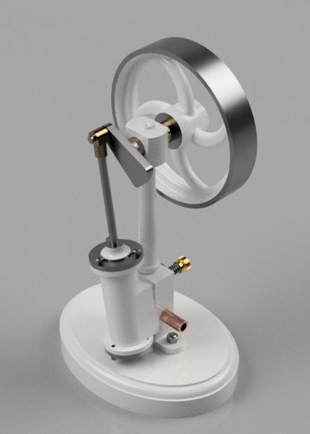
 25215 forum posts 3105 photos 1 articles | Well I think Geoff and Ron can take the blame for this one as their versions got me thinking about making my own. I took the basic design out of Muncaster's book and redrew it in metric at a slightly larger 12mm bore (7/16" original) x 20mm stroke. to keep a constant theme I also drew and CNC cut a curved spoke flywheel from a slice of cast iron. Having recently repaired a Mamod traction engine for some one I thought adding a reverser that works on the same principal would make things a bit more interesting both in the design, build and eventual running stages. Quite a quick build even for me, looking at the dates on the photos I started it on a Friday evening and it was running 8 days later on the Saturday morning. The video starts off with direction and speed being controlled by the reverser then after about 60 seconds I'm just using the flow valve to alter speed, compressor regulator set to about 10PSI throughout. It will run by blowing down the airline but I did not think you would want to see film of me going blue in the face. After taking the video I refilled the small 12lts tank on my compressor and then switched it off at the mains before setting the engine running at approx 100rpm. It ran for 38minutes which is rather good as my compressor is a bit on the loud side Edited By JasonB on 07/03/2020 19:21:49 Edited By JasonB on 30/03/2020 13:56:59 |
| Ron Laden | 08/03/2020 06:33:48 |
 2320 forum posts 452 photos | Excellent Jason, that works a treat. I had a look at my drawing to try and fathom out how the reverser works. I am guessing that the reverser changes over the inlet and exhaust from one side to the other..? How did you do that does the reverser have an exhaust valve each side of a central inlet..? I like the shape of the flywheel spokes almost looks to have motion before it turns, the white colour scheme is nice to, makes a change. |
| JasonB | 08/03/2020 07:09:18 |
25215 forum posts 3105 photos 1 articles | Thanks Ron, I'll post some images from the CAD and do a build thread which should make it all clear. Who knows may even do a set of drawings. The flywheel was a good practice piece as I have a few larger ones that I want to do at some time, They have often been the only bought in item for my 24mm bore engine but now I should be self sufficient. The off white is the same as I used on the Muncaster Entablature engine as I had a bit left in the can. |
| David George 1 | 08/03/2020 07:33:34 |
 2110 forum posts 565 photos | Hi Jason it would be great to do this model with granddaughter if you could do the drawings it would better than the flame licker which takes a bit of starting but she is interested in. David |
| geoff walker 1 | 09/03/2020 13:32:07 |
| 521 forum posts 217 photos | I'm happy to take the blame Jason Engine looks great and like others I would be interested in details of the reversing mechanism. I made the muncaster reverser which works well but yours is neat in that it is built into the engine and not the supply line. Geoff |
| Ron Laden | 12/03/2020 07:16:55 |
2320 forum posts 452 photos | Morning Jason any idea when we might see the build thread, not pushing just interested in seeing how you engineered the reverser. Ron |
| JasonB | 12/03/2020 16:14:55 |
25215 forum posts 3105 photos 1 articles | Might be a week or two, I have just updated the 3D model to what was built and altered a couple of items that I would have done slightly differently. |
| JasonB | 30/03/2020 10:24:43 |
25215 forum posts 3105 photos 1 articles | So with us all on lock down I thought it would be a good time to get a set of drawings together and write up the build if anyone wants a small project to pass the hours. This time rather than separate drawings I have put all 10 sheets into one pdf which should make it easier when looking over them on the computer as you can scroll up and down rather than having to open multiple files. I have also done a Bill of materials for those that like to have one, note that sizes are generally of the finished part so make your own allowances for holding, parting etc. In most cases materials can be substituted as well as methods, anyone with queries please ask. Also if you find anything wrong or missing on the drawings please let me know and I will update as needed.
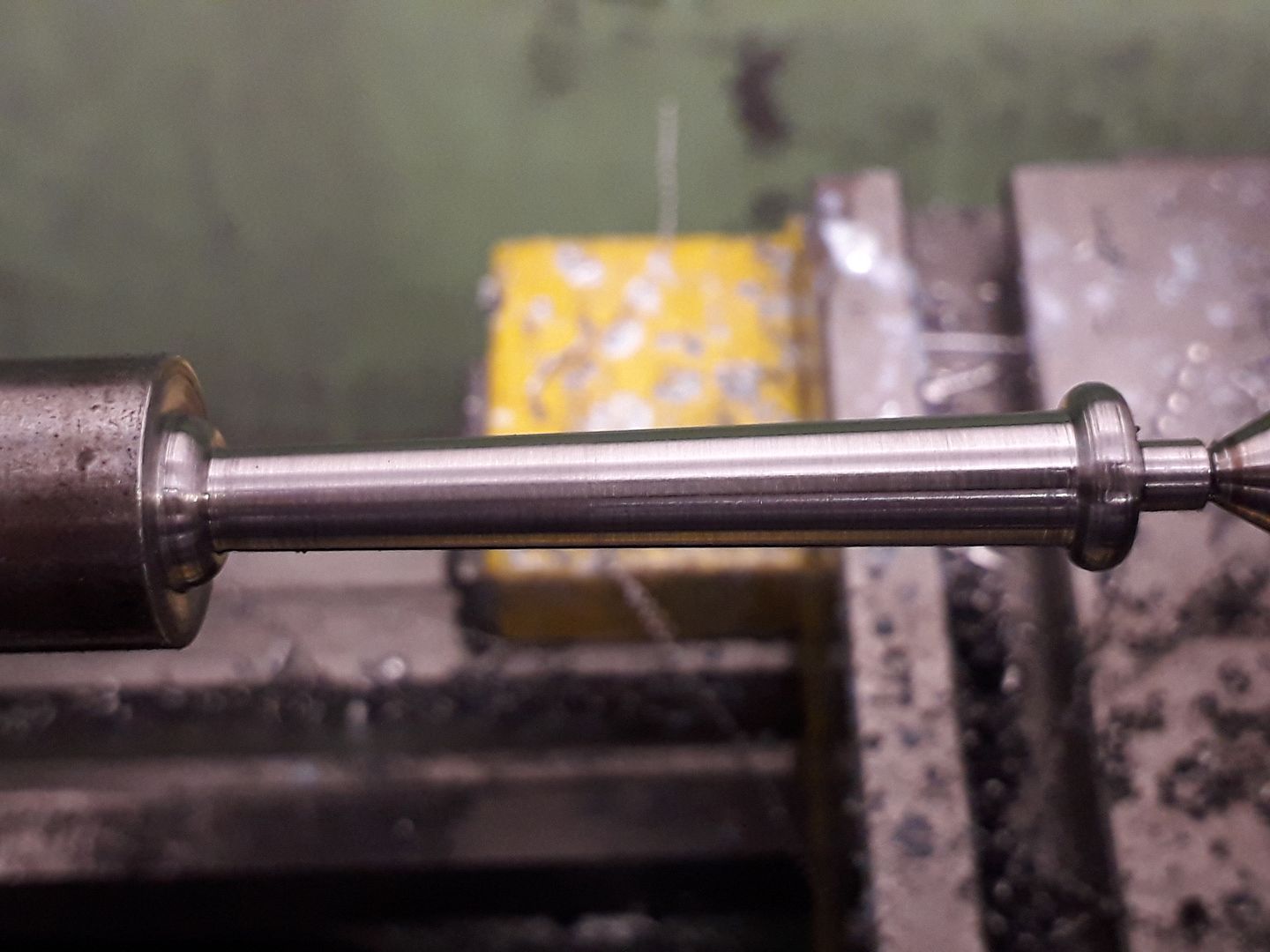
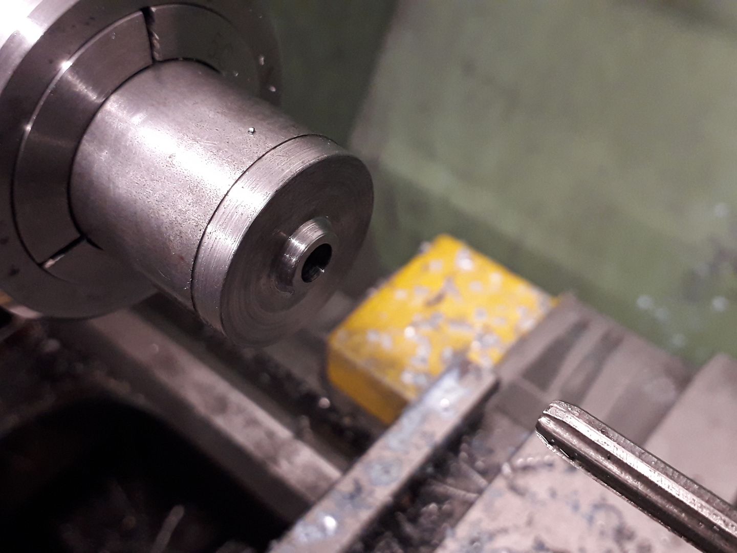
Column Start by facing the end of your 15 or 16mm stock and then form the spigot on the end followed by a small ctr drilled hole. The material can then be pulled further out of the chuck and tailstock support used while the tapered section and decorative beads are turned.
Transfer the part to the mill and hold by the remaining bar in a collet block or indexer to mill the two flats at the top followed by drilling and reaming for the bearing.
With the work back in the lathe form the small boss for the oil hole before parting off. The oil hole can be drilled while lightly holding the top of the column in a collet or in the 4-jaw, you could even leave it until later and just use the bench drill. Bearing This is a straight forward turning job, the column can be used to gauge the outside diameter and the 5mm hole is best reamed. The bearing is Loctited into place with 1mm protruding on the cylinder side and then the oil hole drilled through but don't do either of these things yet.
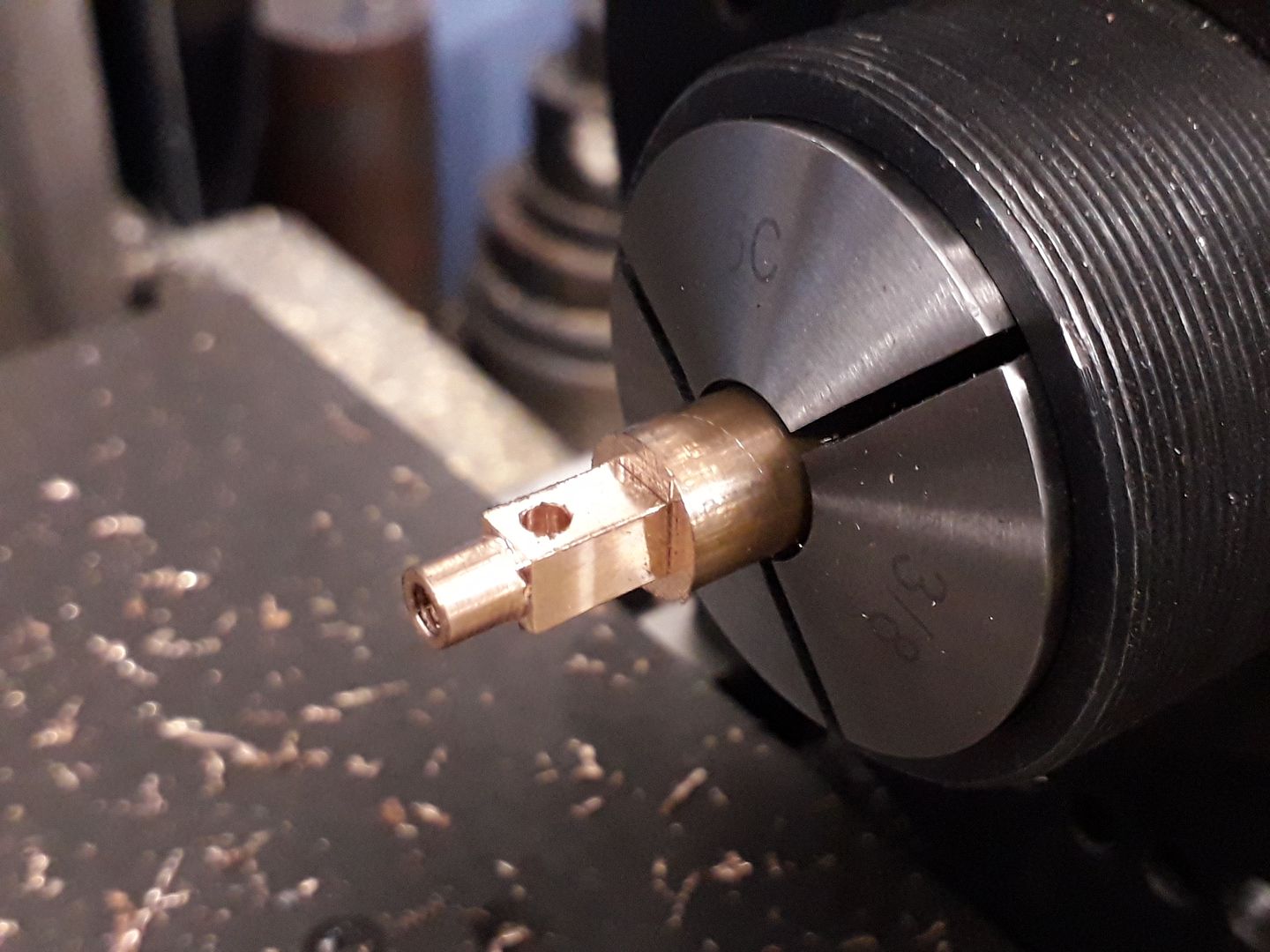
Crankshaft A very easy part to make from either Precision Ground Mild Steel or Silver Steel (Drill Rod) but leave it say 1.0mm over length for now. Crankpin Another simple part from Silver steel Crank Web Start by forming the 8mm dia boss on the end of a piece of 25mm dia steel then drill and ream 5mm. Part or saw off leaving the web 1mm over thickness.
Transfer to the mill, locate the ctr and then move 10mm to one side to drill for the crankpin.
To mill the tapered sides slip the crankshaft material into the 5mm hole letting it rest on the vice jaws and the 2.5mm drill into the pin's hole but raise this up 2.75, you can see the black 2.8mm drill shank I used for this and then mill one side before repeating for the other though there is not so much to hold this time around so light cuts after sawing off most of the waste.
After rounding the corners to the final profile with a file the web can be Loctited to the crankshaft with 638 or 648 and set aside to dry. Then holding the shaft preferably in a collet a couple of cuts can be taken across the end of the web & shaft to bring them both to final size. deburr and then Loctite the pin into place. |
| Roderick Jenkins | 30/03/2020 10:55:26 |
 2376 forum posts 800 photos | OMG... if Jason can't go to work he'll be producing 3 new engines a week! How will we keep up? Seriously though, we appreciate your efforts Keep well, Rod |
| JasonB | 30/03/2020 12:31:53 |
25215 forum posts 3105 photos 1 articles | Thanks Rod, just don't expect a full write up and drawings at the same rate! Actually I've probably spent more time with the Bonsai over the last couple of weeks than in the workshop as it's the time of year for repotting etc. have not really got myself motivated for a new build yet though there are a few casting sets sitting about and scratch builds that are 3D modelled, I did dig out my Hoglet that has been sitting around almost done for too long and have progressed that, just waiting for a couple of magnets to trip the ignition. How is your Farm Boy? |
| paul rayner | 30/03/2020 13:36:36 |
| 187 forum posts 46 photos | come on Jason, give us a chance. I haven't finished the last one yet. On a serious note keep em coming. regards Paul
|
| Ron Laden | 31/03/2020 09:49:00 |
2320 forum posts 452 photos | Great stuff Jason good to see how the reverser works and I like the notches machined on the back face for the control lever, thats really neat. I enjoyed making mine it makes up into a nice looking engine that runs well, would recommend it for anyone looking for a small project, doesnt take long though it took me 2-3 times as long as Jasons record time. Mine doesnt have the reverser so I would say go with Jasons as the reverser adds more interest. |
| Martin Connelly | 31/03/2020 10:04:12 |
 2549 forum posts 235 photos | I still have my Mamod SE2 from 1967. Like this it is a single ended single oscillating cylinder engine with a reverse/regulator lever. Martin C |
| JasonB | 31/03/2020 13:56:40 |
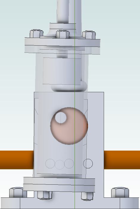
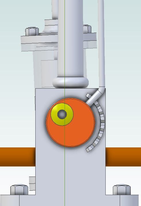
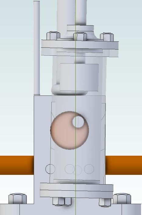
25215 forum posts 3105 photos 1 articles | Before going on with the build I'll explain a bit about the reverser as the parts for that are the next to be made. As I mentioned I recently repaired a Mamod traction engine for someone and got the idea from the reverse lever fitted to them which is simply a pressed steel lever that rotates and has an eccentric hole for the cylinder pivot.
There are three ports on the base, a central one that is the inlet with the ones either side acting as exhausts. As the cylinders pivot point is moved from one side to the other it will use two of the three holes depending on what side of ctr it is. So with the lever down the pivot moves towards the right when viewed from the back.
Looking at the front you can see that the cylinder will oscillate between the left exhaust and central inlet.
If the lever is now moved upwards so that the pivot is now on the opposite side
Which means that the cylinder is now oscillating between the right hand exhaust and central inlet, this has the effect of making the upward power stroke take place when the crank is on the other side of centre thus reversing the direction in which the flywheel rotates. An added bonus of this arrangement is that with the lever placed somewhere between these two extreams the amount of time that the ports are open for is altered so the reverser can also be used to control speed and or save air/steam.
|
| JasonB | 31/03/2020 14:22:12 |
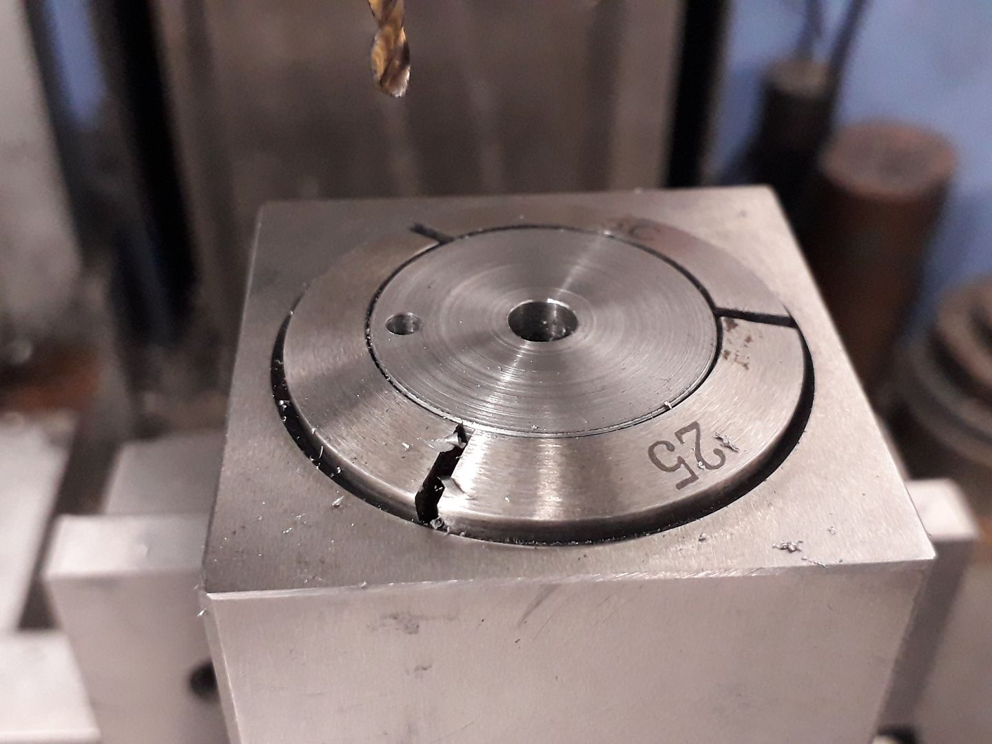
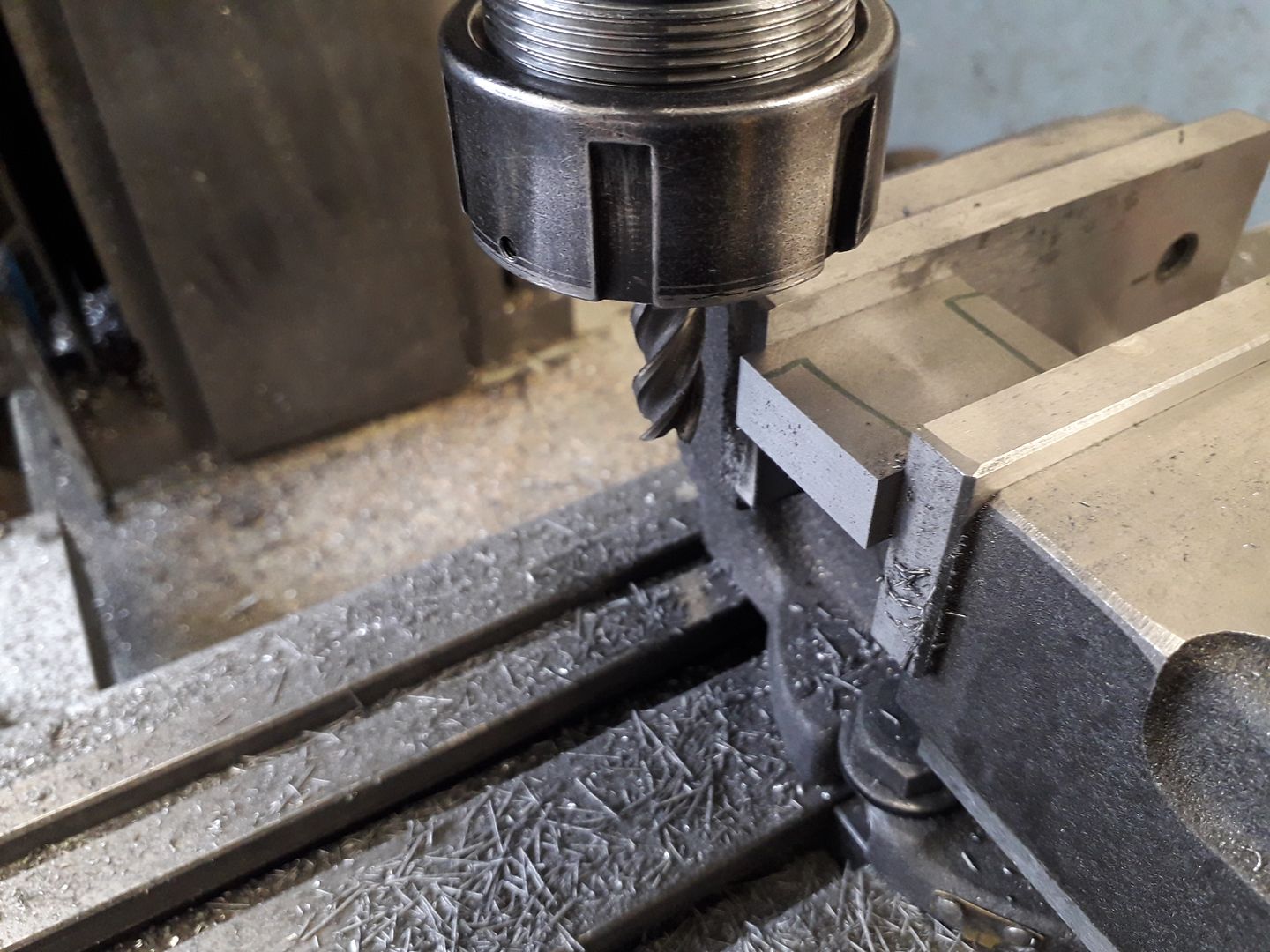
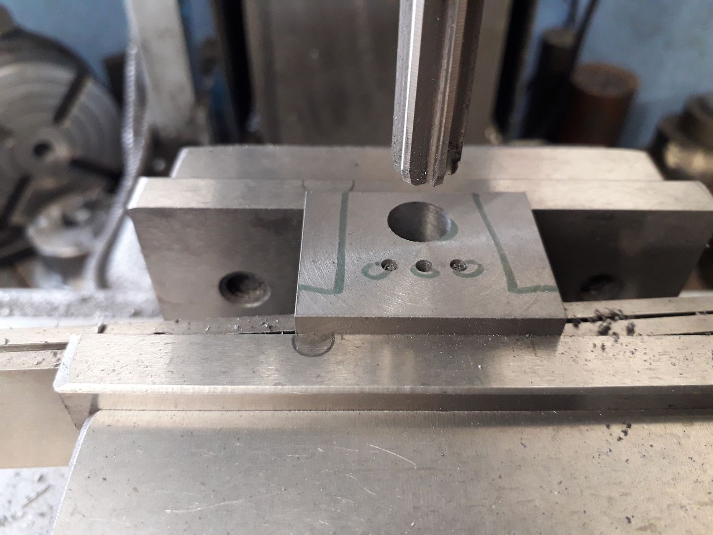
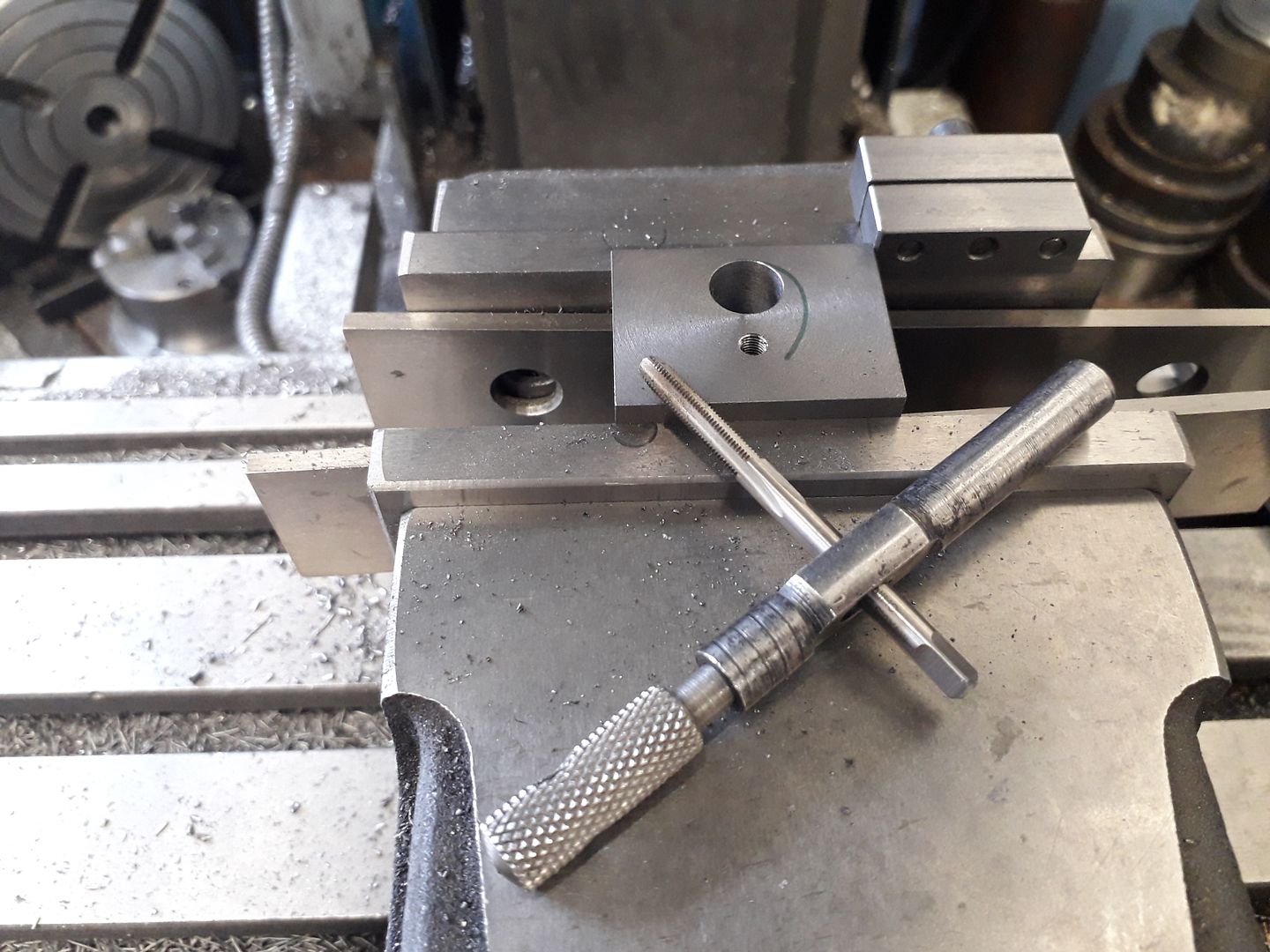
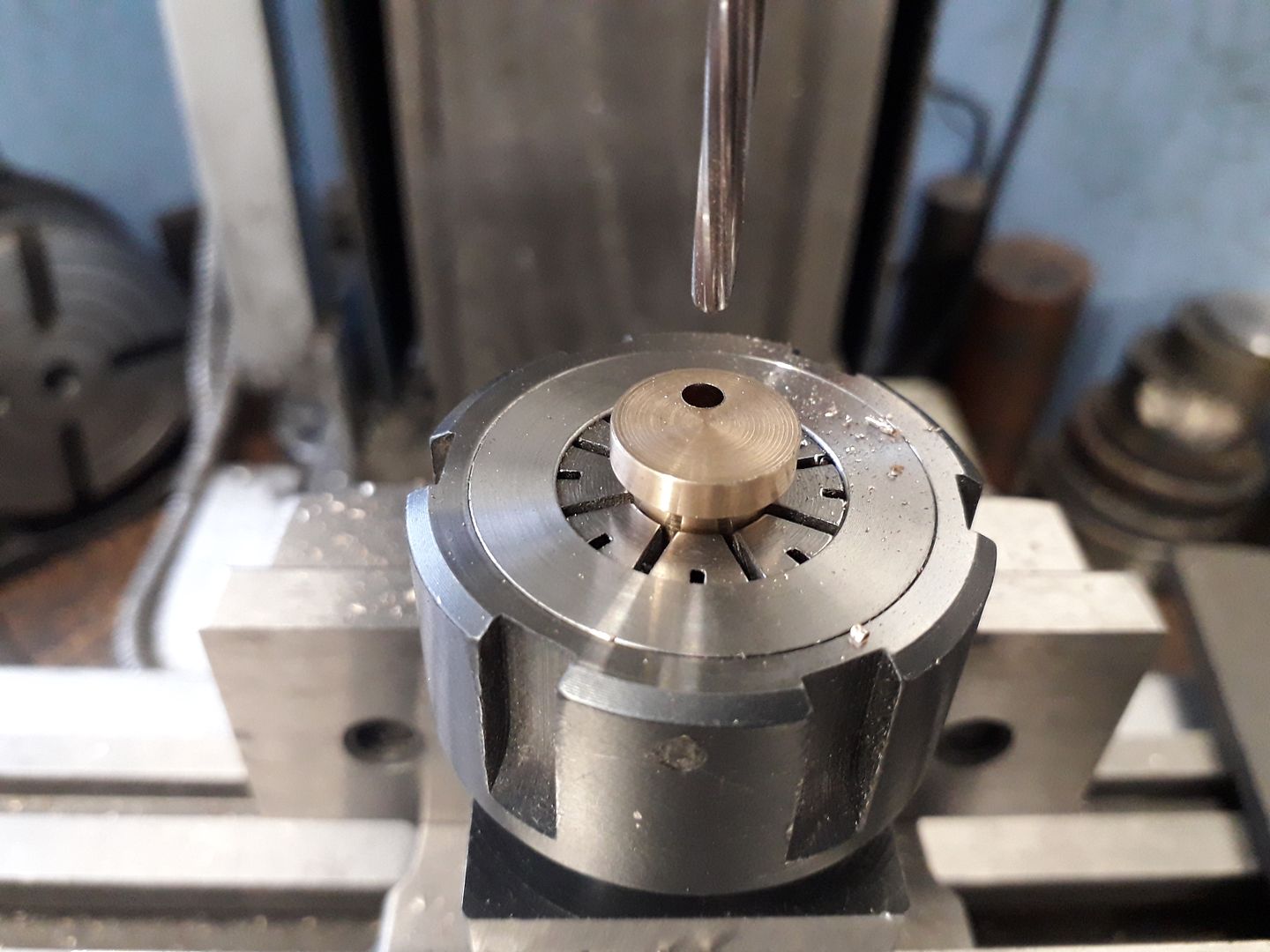
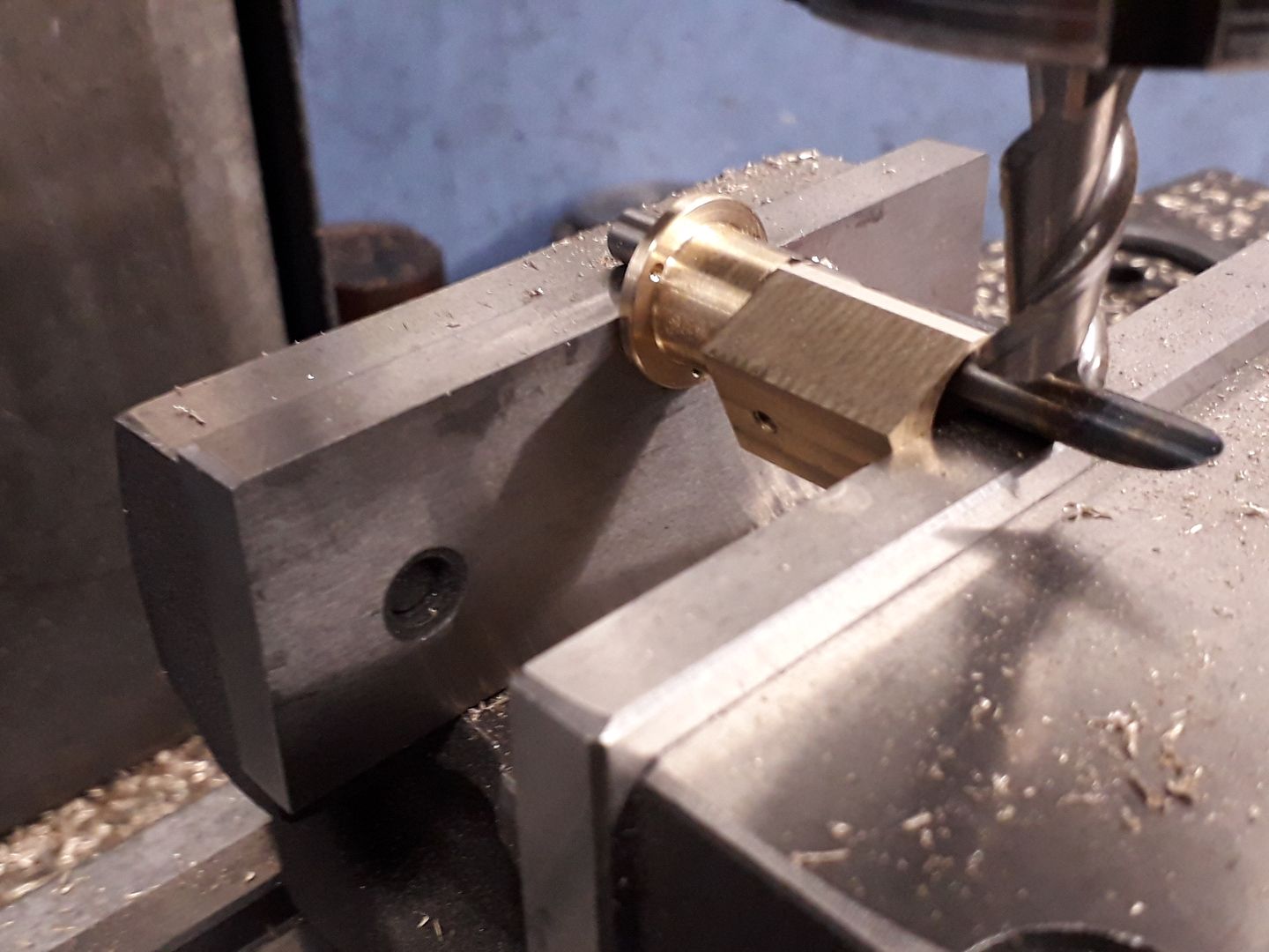
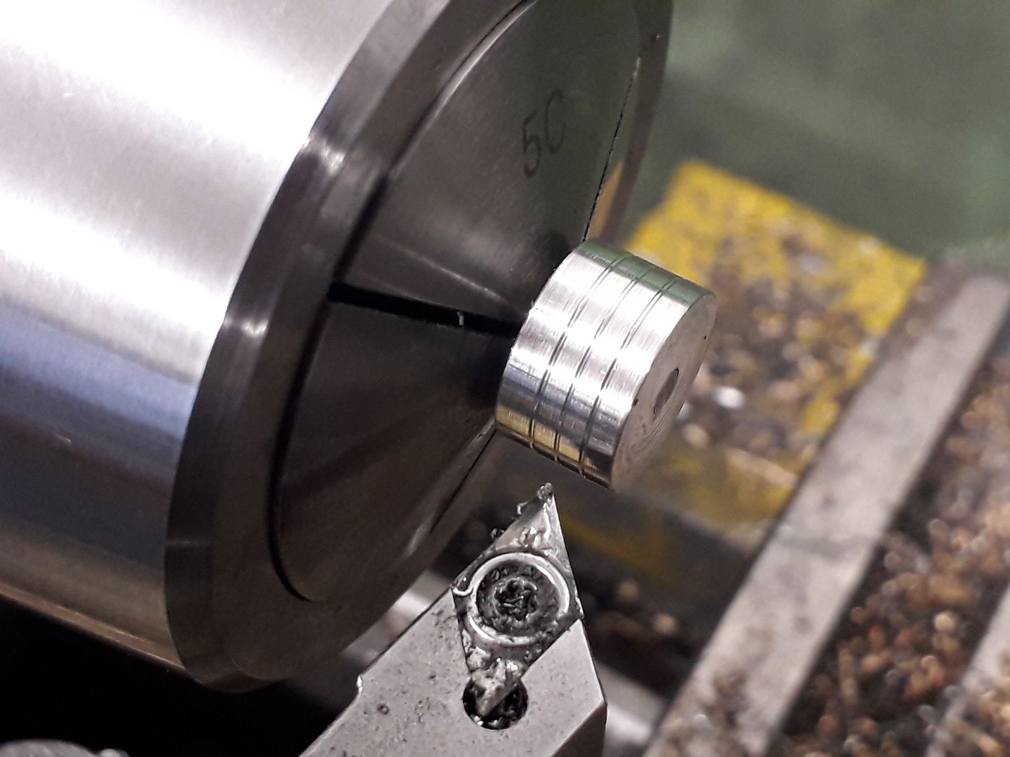
25215 forum posts 3105 photos 1 articles | [b]Column Base[/b] This is probably the most complex part of the model so take your time. I chose to make mine from a slice cut off a piece of 50mm dia cast iron bar though it can just be squeezed out of 1 3/4" material if you have that to hand. Once the bar had been faced off both sides in the lathe to the required 11mm thickness it was transfered to the mill to form the basic 31 x 37mm rectangle.
Holding the block in the vice with what would be the port face upwards the work was centred in X and the bottom edge located so that the tree 2.5mm ports could be drilled to depth and then the hole for the pivot drilled and reamed 10mm. To save putting any holes in the wrong place I used a Sharpie to roughly indicate where the various features should be.
If you don't want to have the air supply come in from the side of the base then the work can be turned the other way up and a 3.5mm hole drilled to join the inlet port and then tapped M4 x 0.5. so that the air can come in from the back of the column.
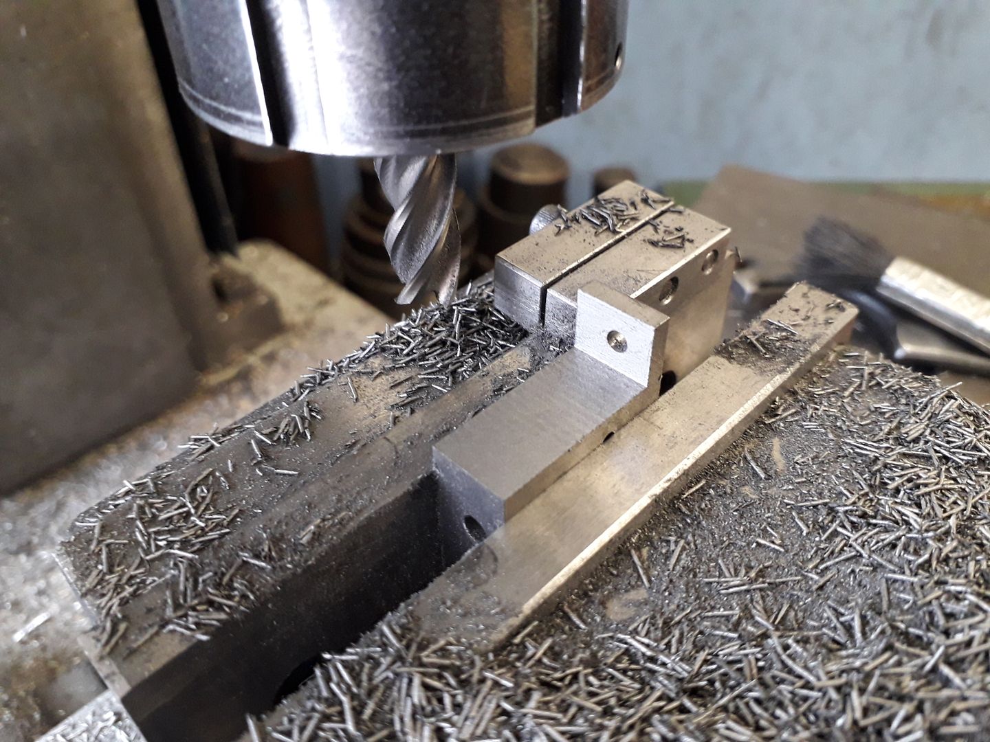
Next the sides can be milled away to form the feet followed by drilling and tapping M5 x 0.5 either side for the exhausts.
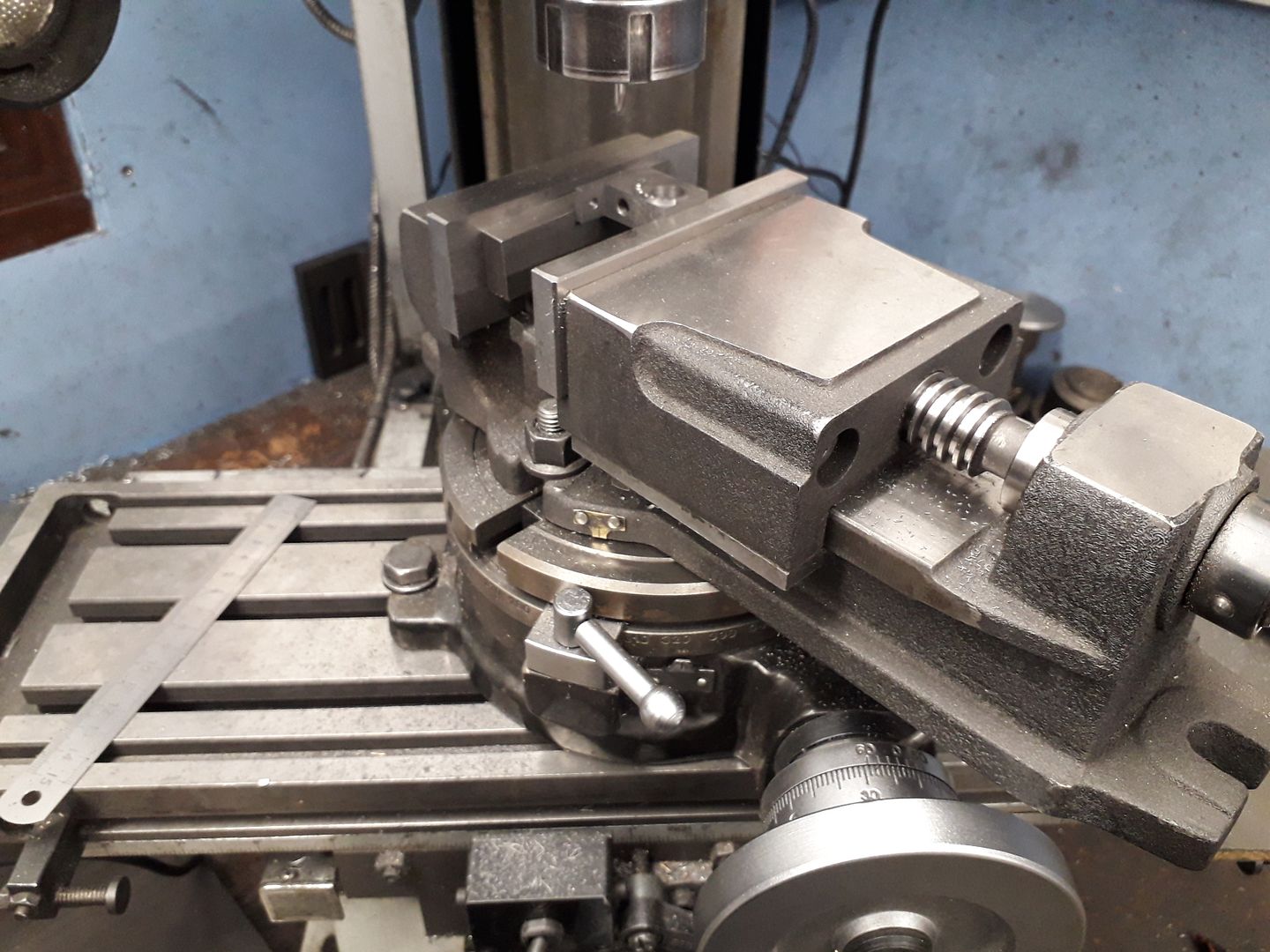
To form the detent arc I chose to hold the job in my mill vice which was in turn mounted onto the rotary table but the Arc could just as easily be turned on the lathe and then the excess milled away. The Vee notches were cut using a spotting drill at 15degree intervals, again if not using a rotary table they could simply be filed with a needle file.
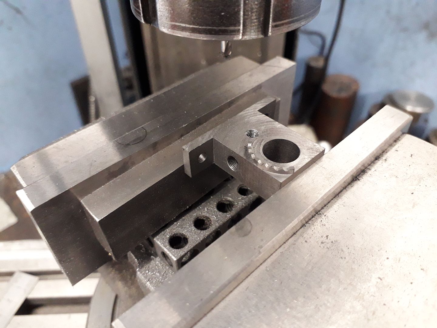
The two 3mm holes to mount the engine to the base, the 2.5mm air supply up to the inlet port and 5mm dia one for the column spigot are simple enough, filing buttons can be used to shape the two feet. Edited By JasonB on 31/03/2020 14:24:18 |
| JasonB | 02/04/2020 17:03:26 |
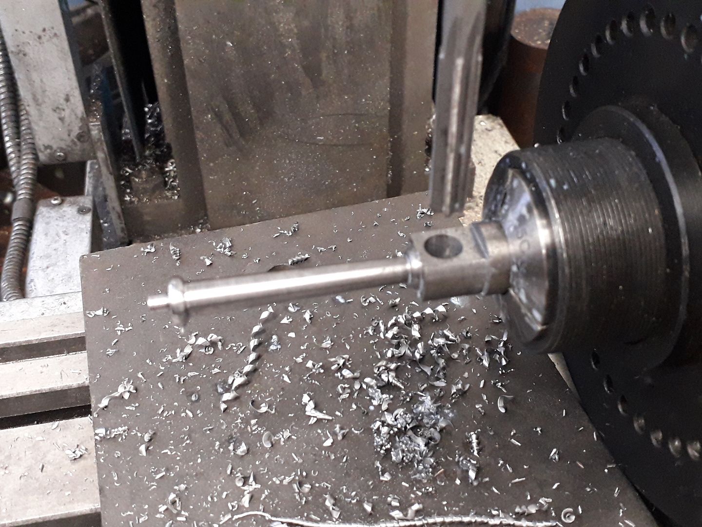
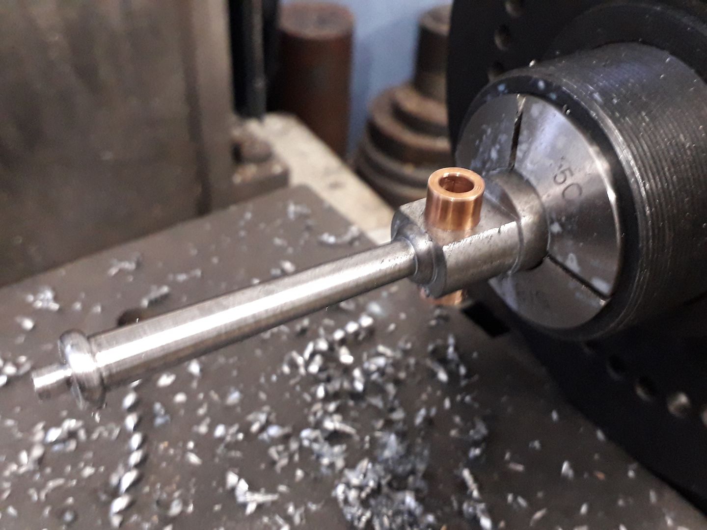
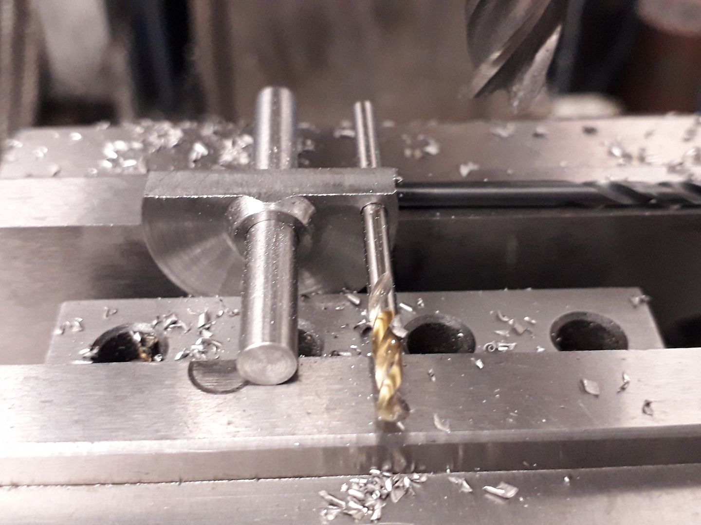
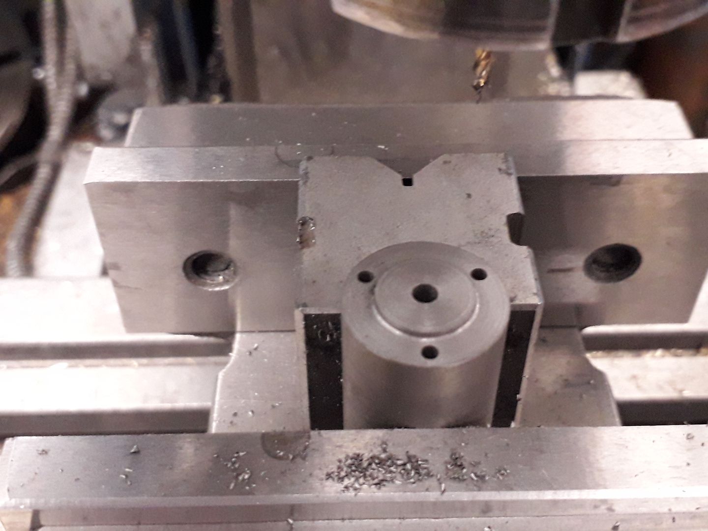
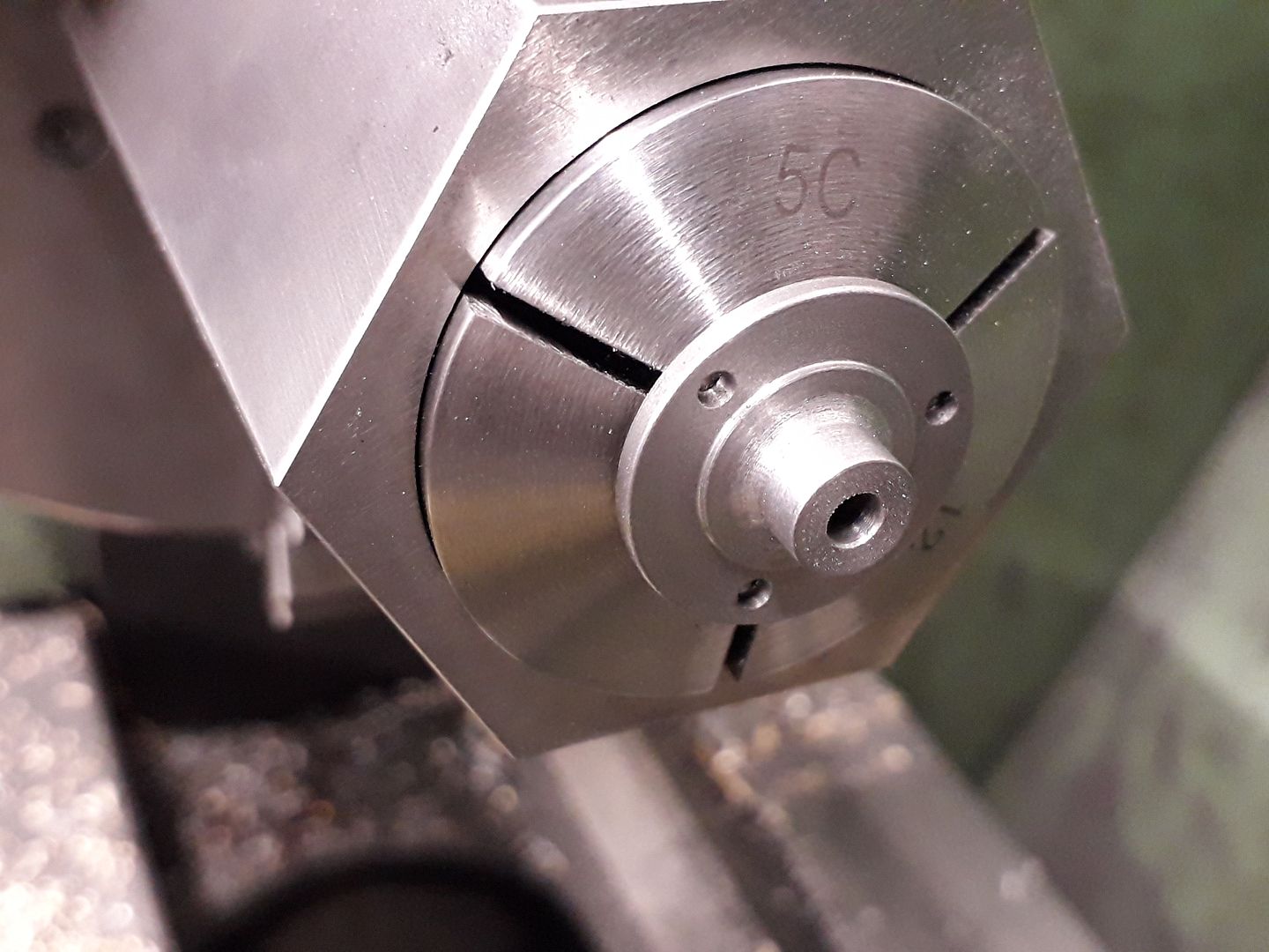
25215 forum posts 3105 photos 1 articles | After turning the pivot bush it can be held in a collet block to firstly drill an dream the 3mm hole.
The collet block can then be repositioned so that the 1.5mm hole can be drilled at right angles to the first.
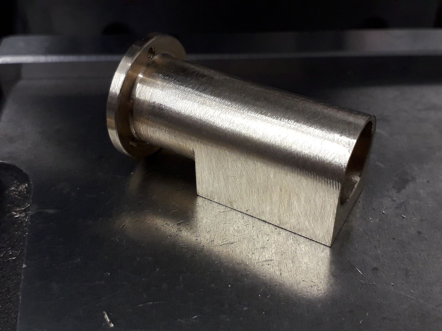
The size and shape of the adjusting nut is not critical and a diamond knurl will do if you don't have straight wheels. The pivot shaft is just a simple rod threaded at either end and hopefully you can find a spring of approx the right proportions to that shown. The reversing lever is bent from 1.5mm rod and Loctited into the pivot bush. The column can also be joined to the base at this stage with Loctite if you have a good fir or JBWeld if there is any movement. To endure the part face is at right angles to the bearing hole lay the two parts onto a flat surface when bonding and if you have a vice that opens far enough that can be used to holed them together while the adhesive dries. Once it has the cankshaft bearing can be loctited into place with 1mm protruding on the port face side and then the oil hole drilled through. You should have something that looks like this if all has gone to plan.
|
| JasonB | 03/04/2020 19:05:32 |
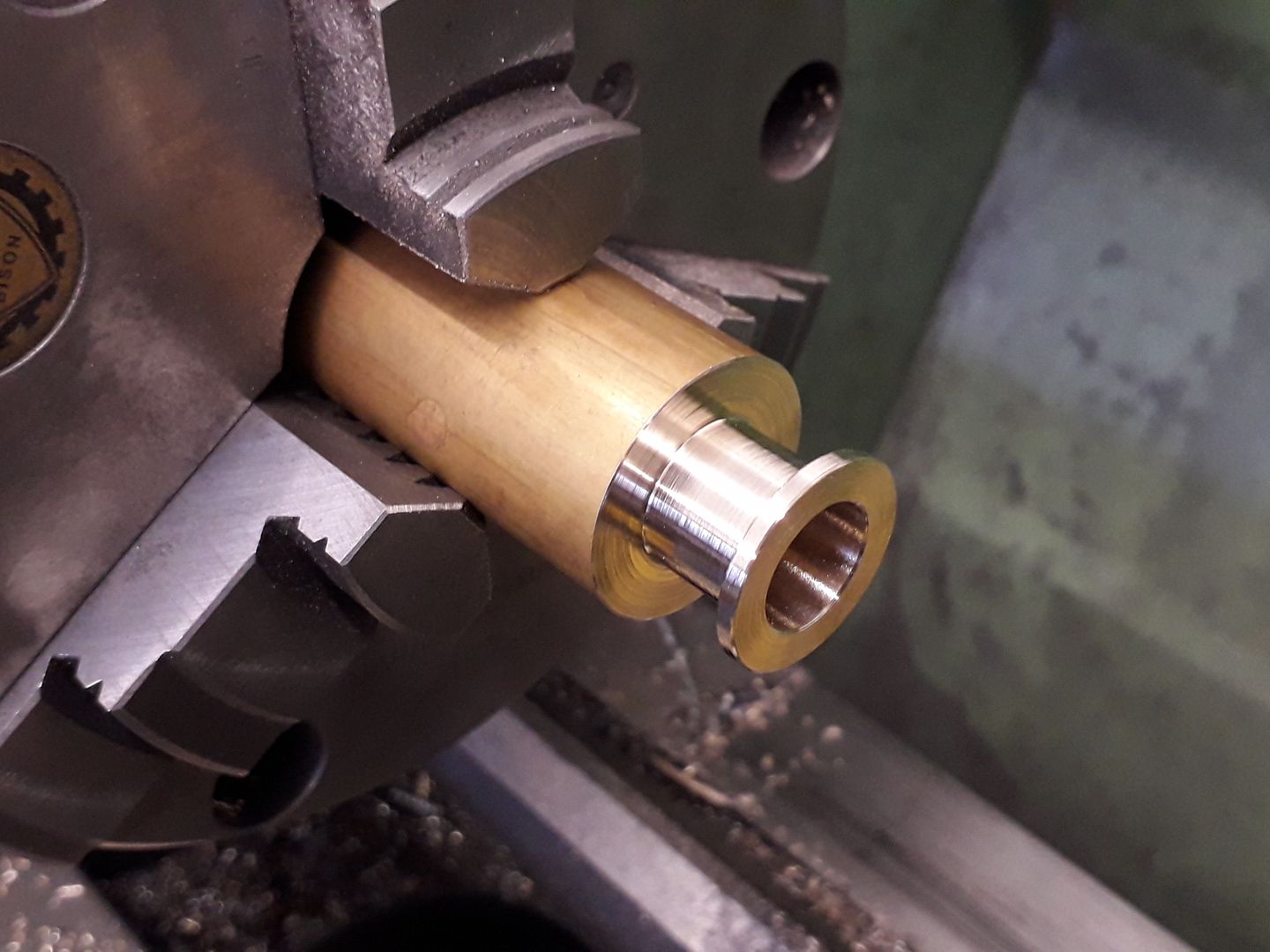
25215 forum posts 3105 photos 1 articles | The cylinder can be cut from 25mm or 1" stock without the need to offset the bore. Start by facing off and then reduce the end to 20mm diameter followed by turning the 14mm outside diameter with a parting tool down to where the top of the port face comes. While still in the lathe drill and then bore to the finished 12mm dia.
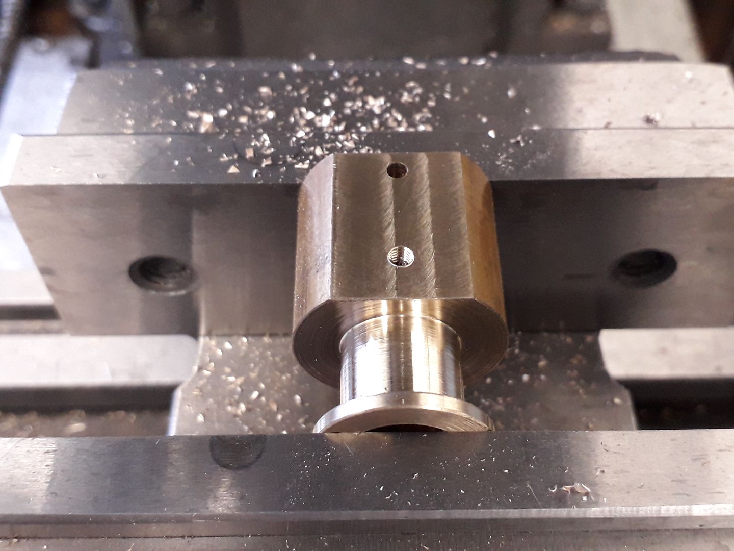
The part face can then be milled flat and while in the vice drill the inlet hole 2.5mm, tap M3 for the pivot pin taking great care not to let the tip of the drill go deeper than 3.5mm then finally add the vent hole just below the flange. The port face can be lightly rubbed onto some 1000g wet and dry laid on a flat surface to remove any slight raised material around the holes this also keeps the edge of the inlet hole nice and crisp stop air bleeding between ports if there is any chamfer to the edge.
With the port face against the fixed jaw the three tapped holes can be orientated easily.
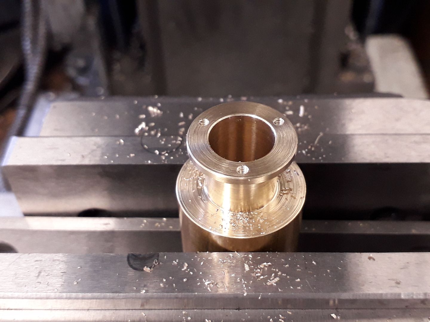
Mill the two sides of the cylinder flat and then slip a piece of rod through the bore and rest that on the top of the vice jaws and take a series of cuts rotating the work about 5degrees between each cut which will give the curved surface as a series of facets.
Which can easily be blended with a file and finished with Emery cloth.
|
| JasonB | 05/04/2020 16:37:03 |
25215 forum posts 3105 photos 1 articles | Top Cover The cylinder top cover helps guide the piston rod so turn the 1mm deep spigot and ream the hole at the same setting. Then transfer the work to the mill so that the three holes can be drilled while you have plenty to hold.
Bottom Flange The bottom flange can be made in much the same way but with threaded holes and is fitted to the end of the cylinder with Loctite, 648 if you intend to run on steam. Bottom Cover The bottom cover is just a dummy and made like the two items above. You could omit this part if you wanted in which case don't bother to drill and tap the bottom flange. Big End I started with some 3/8" round stock and turned the end down to 4.5 mm and tapped M3 before using the spin indexer to mill the 5mm square and drill & ream the cross hole. After sawing off from the bar filing buttons can be used to round over the end.
Piston Rod Simply a piece of 3mm stainless steel threaded M3 at one end, use a tailstock die holder if you have one to make sure the big end screws on squarely. Piston Rough this out a little over diameter and cut the oil grooves before attaching to the piston rod with Loctite, 648 again if running on steam. Once this has cured hold by the rod in a collet, split bush or 4-jaw and skim the piston so it is a sliding fit in the cylinder.
|
| Ron Laden | 06/04/2020 07:28:08 |
2320 forum posts 452 photos | Another of your excellent build threads Jason, for those that have a go at your designs they really do get their hand held through the build, it's much appreciated we'll certainly from me at least. My JDW version which I built was drawn with a single piston O ring but changed to two oil grooves, I see you have gone with 3 grooves and just wondered what your thinking was on that. Ron |
| JasonB | 06/04/2020 07:46:32 |
25215 forum posts 3105 photos 1 articles | 'twas easy to place one in the middle and then one in each half doing it by eye though the large photo shows I was a bit off
Actually I have put two on the drawing and doubt 2 or 3 would make much difference. |


Please login to post a reply.
Magazine Locator
Want the latest issue of Model Engineer or Model Engineers' Workshop? Use our magazine locator links to find your nearest stockist!
Sign up to our Newsletter
Sign up to our newsletter and get a free digital issue.
You can unsubscribe at anytime. View our privacy policy at www.mortons.co.uk/privacy
Latest Forum Posts
- *Oct 2023: FORUM MIGRATION TIMELINE*
05/10/2023 07:57:11 - Making ER11 collet chuck
05/10/2023 07:56:24 - What did you do today? 2023
05/10/2023 07:25:01 - Orrery
05/10/2023 06:00:41 - Wera hand-tools
05/10/2023 05:47:07 - New member
05/10/2023 04:40:11 - Problems with external pot on at1 vfd
05/10/2023 00:06:32 - Drain plug
04/10/2023 23:36:17 - digi phase converter for 10 machines.....
04/10/2023 23:13:48 - Winter Storage Of Locomotives
04/10/2023 21:02:11 - More Latest Posts...
- View All Topics
Support Our Partners


Shopping Partners
Subscription Offer

Latest "For Sale" Ads
- Reeves** - Rebuilt Royal Scot by Martin Evans
by John Broughton
£300.00 - BRITANNIA 5" GAUGE James Perrier
by Jon Seabright 1
£2,500.00 - Drill Grinder - for restoration
by Nigel Graham 2
£0.00 - WARCO WM18 MILLING MACHINE
by Alex Chudley
£1,200.00 - MYFORD SUPER 7 LATHE
by Alex Chudley
£2,000.00 - More "For Sale" Ads...
Latest "Wanted" Ads
- D1-3 backplate
by Michael Horley
Price Not Specified - fixed steady for a Colchester bantam mark1 800
by George Jervis
Price Not Specified - lbsc pansy
by JACK SIDEBOTHAM
Price Not Specified - Pratt Burnerd multifit chuck key.
by Tim Riome
Price Not Specified - BANDSAW BLADE WELDER
by HUGH
Price Not Specified - More "Wanted" Ads...
Get In Touch!
Do you want to contact the Model Engineer and Model Engineers' Workshop team?
You can contact us by phone, mail or email about the magazines including becoming a contributor, submitting reader's letters or making queries about articles. You can also get in touch about this website, advertising or other general issues.
Click THIS LINK for full contact details.
For subscription issues please see THIS LINK.
Digital Back Issues


Donate

 Register
 Log-in
Model Engineer Magazine
- Percival Marshall
- M.E. History
- LittleLEC
- M.E. Clock

ME Workshop
- An Adcock
- & Shipley
- Horizontal
- Mill

Subscribe Now
- Great savings
- Delivered to your door

Pre-order your copy!
- Delivered to your doorstep!
- Free UK delivery!
All Forum Topics > Stationary engines > Muncaster No1 with Reverser BUILD & DRAWINGS