Forum sponsored by:

Bench grinder troubleshooting
| Gene Pavlovsky | 01/02/2020 15:23:51 |
| 124 forum posts 80 photos | I've bought an 1998 Elektra Beckum DS 200W bench grinder. I was told by the seller that it had never been used. It seems to be the truth, as the wheels appear to be original and are indeed unused, and the grinder itself also looks like new. However, when I plugged it in, it failed to start. Spinning the wheel by hand made it start (it took many seconds to spin up to proper speed). This grinder has a start capacitor and a centrifugal switch. The capacitor indeed had leaked, and was not holding any charge. I've assumed this is the (only) problem, and ordered a replacement cap (exactly the same model). However, it didn't improve the situation. I've then checked the resistances. For the main winding my multimeter is showing 8 Ohms, but there is open circuit between the wire that goes to the centrifugal switch, and the common wire. Making me think either the centrifugal switch is stuck open, or the starting winding is blown. I wonder what would be more likely, considering that the grinder appears to have never been used? Is it practical to try and disassemble the motor further to investigate? What would be necessary to do to get inside the motor? Would I have to take off both grinding wheels and motor end caps? Thanks --Gene |
| not done it yet | 01/02/2020 16:01:38 |
| 7517 forum posts 20 photos | Presumably it sits and buzzes unless you spin it? Little option but to dismantle to ascertain if it is the centrifugal switch or the windings. I’ve dismantled grinders in the past, for start winding switch problems, but not your make/model. I would no more trust the quality of the new capacitor - than the seller knowing it was faulty before selling it.🙂 Good luck. |
| Gene Pavlovsky | 01/02/2020 16:21:06 |
| 124 forum posts 80 photos | Indeed, it just sits and buzzes. The seller might or might not have known it's not working. I found it on a German classifieds website, description said it's new (although old), boxed (original packaging), never used, local pickup only. The seller was kind enough to post it to me (Luxembourg). To me it was sorta obvious that if it's advertised like this, it must be working, so I never actually asked if he tried to turn it on. Good education for me The new capacitor is fine, my multimeter shows it's capacitance to be right in the middle of the specified range, charging it with 220 V and then shorting it with a screwdriver gives a nice big spark. I guess I have to dismantle it, no other choice |
| Phil Whitley | 01/02/2020 18:54:27 |
 1533 forum posts 147 photos | Corrosion on the contacts of the centrifugal switch is probably the cause, or even a wire off, very unlikely to be an open circuit winding.They can stick open, but it is unusual. Strip it down and have a look! Phil Edited By Phil Whitley on 01/02/2020 18:56:17 Edited By Phil Whitley on 01/02/2020 19:01:52 |
| Brian Morehen | 01/02/2020 19:26:44 |
 191 forum posts 11 photos | 100, Percent the centrifugal switch part that moves on the motor shaft has stuck quite common on motors that have not been used for some time Yes you will have to remove both wheels and the end caps from the motor . Be carefull when moveing the end caps because the bearings are in the end , Will need to be firmly pushed a block of wood and hammer to split Take care once they have. split Easy to damage Centifugal Switch good luck Brian
|
| Gene Pavlovsky | 01/02/2020 22:23:21 |
| 124 forum posts 80 photos | Well, I took it apart. Wasn't that hard to do with a block of wood and a plastic-faced recoil-less hammer. Surprisingly, the centrifugal switch turned out to be in order. The starting winding, however, is an open circuit. I've read somewhere that commonly the problem spot can be where the input wire is soldered to the enameled winding's wire. So I cut it open a bit until that spot, however that joint is fine. I scraped the enamel a short distance away from the joint and there's continuity between that spot and the input wire. I am really curious how a grinder that looks like it had not been used, ended up like this. Is it now only good for recycling center? The capacitor and the wheels could be useful (or I can sell them), anything else useful to salvage?
|
| John Paton 1 | 01/02/2020 23:03:30 |
 327 forum posts 20 photos | Don't give up just yet! Did you manage to ascertain if the switch was actually working? If it appeared to be ok then be ready to suspect the capacitor itself. They often fail after 10 years ( depending upon the make) and actually dislike being left discharged. some capacitors 'reform' over a relatively short period of use and recover some of their capacitance ( but will still be suspect) others may show signs of seepage around the join of their 'end plate) to the aluminium can. Disconnect one lead of the capacitor and take an ohmmeter reading across the terminals ( in both polarity directions). If you get zero ohms both ways it has gone short circuit.if one polarity or the other it starts almost short circuit but the meter reading then rises over few seconds it suggests that the capacitor is functioning to some degree. If the latter it would seem that there is another problem. I would start by looking at the capacitor with the symptoms you describe because it is easy and then move onto the centrifugal switch can also be the problem. I suspect we all go by our own experiences and for me I have had more failures due to capacitors and then cooked windings from poor ventilation or overloading of the motor. I have only experienced switch faults on hard worked motors which have done lots of stop start work. i wou.d hazard that switch is more likely to be proble,attic with damp storage and capacitor mor likely if stored somewhere hot - perhaps an unventilated roofspace which gets hot in summer.
you can test the switch by shorting out the capacitor terminals with a bit of wire,putting the meter across the line and neutral wires to the motor and then spinning up the motor using something like a rubber bung on the end of an electric drill pressing obtuse the end of the grinder shaft (spinning it in the correct direction) watch the meter to see if the reading varies as you get up to, or slow down from, speed. obviously don't have the machine connected to the mains while doing this!! You ,at find that the motor creates its own voltage while doing this in which case test with volts scale, if not use the ohms. You aren't looking for a particular reading, just a step change in the reading as the centrifugal switch cuts in and out. |
| John Paton 1 | 01/02/2020 23:06:23 |
327 forum posts 20 photos | Sorry for typos in the above but I hope it still makes sense! |
| Enough! | 01/02/2020 23:06:39 |
| 1719 forum posts 1 photos | Posted by Gene Pavlovsky on 01/02/2020 22:23:21:
I am really curious how a grinder that looks like it had not been used, ended up like this.
Perhaps it didn't so much end up like this as start like this. If the original owner bought it new, plugged it in and it didn't work he may have shelved it pro tem then not got around to returning it (been there, done that) or fixing it. That would be my guess if it's apparently new but with an open winding. Edited By Bandersnatch on 01/02/2020 23:09:38 |
| John Paton 1 | 01/02/2020 23:11:13 |
327 forum posts 20 photos | Sorry again - just re -read and see that you have eliminated capacitor - ignore my post unless you fancy my 'seat of the pants' diagnostic methods ( they might be crude but work for me as a first ' non destructive' exploration) |
| Gene Pavlovsky | 01/02/2020 23:12:32 |
| 124 forum posts 80 photos | John, thanks for your detailed advice. However you may have missed that I had already replaced the capacitor (which indeed leaked and lost it's mojo), and had tested the new capacitor and found it to be operational. The centrifugal switch also seems to be working correctly, however the start winding is an open circuit (measured the resistance at the winding itself, so the centrifugal switch and/or capacitor can't be causing a false result in this case). Bandersnatch, yeah I think you might be right. That idea also visited my head... |
| Ian P | 01/02/2020 23:48:45 |
 2747 forum posts 123 photos | I'm in the 'dont give up yet' camp. You've checked one end of the start winding (the green wire), but what about the other end? The windings do not look overheated or burnt and you know it runs if you start it by hand but as it not really a usable machine there is not much to lose delving a bit deeper into the winding connections. If there are only three wire connections brought out then the common wire should connect to both windings. Locating and examining the common point must surely be worthwhile. Ian P
|
| Gene Pavlovsky | 01/02/2020 23:53:09 |
| 124 forum posts 80 photos | Ian, yes you're right. The other end is the (common) black wire. I will examine it tomorrow. I have a (sometimes bad) habit to try every possible way before I give up. Sometimes I do succeed and that feels good, sometimes it is just a giant waste of time |
| Kiwi Bloke | 02/02/2020 00:25:56 |
| 912 forum posts 3 photos | More encouragement not to give up! I'm not clear whether you've isolated the start winding and tested it for continuity. It would be really bad luck if the start winding has burned out or was broken in manufacture. I'd still suspect a wiring or connection problem. Never trust soldered, welded or crimped joints, however good they look! You've nothing to lose - dive in deeper! Good luck! |
| Brian Morehen | 02/02/2020 08:47:16 |
191 forum posts 11 photos | No continuity through the start winding sounds bad check that there is no thermal cut out buried into the start winding that has gone open circuit,Then look carefully all round the windins that there is not a break in one of the coil windings hve found this problem myself , also that you have not got a solder dry joint good luck. Everything looks to good to give up on jusy yet Just Double Check everything again. Brian |
| John Baron | 02/02/2020 09:53:17 |
 520 forum posts 194 photos | Posted by Gene Pavlovsky on 01/02/2020 22:23:21:
That blob of resin on the winding look awfully suspicious ! Could it be covering up a break in the wire ?
|
| Gene Pavlovsky | 02/02/2020 20:27:47 |
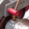
| 124 forum posts 80 photos | Thanks everyone for the encouragement not to give up. Yesterday I was about to throw it out, but I followed up on the black wire, and indeed there was a break where it connects to the two windings. I also carefully removed the blob of resin mentioned by John Baron, but it was just excess resin, no breaks hiding under it. The copper was quite oxidized so I cut a portion of both the black wire and the enameled wires, and soldered it all together. I covered it in heat-shrink, and shoved it back where it was. Both windings now show reasonable values on the multimeter - 8 Ohms on the main winding, 9.4 Ohms on the start winding. Now to put some finish touches on all of this, before I put it back together... To get to the wires, I had to cut several of the fabric "straps", it would be nice to fix that back somehow, to immobilize the soldered joints (to prevent them breaking later due to vibration etc). I've noticed that all the materials used there seem to be high-temperature resistant, e.g. the wires insulation is silicone, not PVC. I bet the fabric straps are some sort of high-temp fabric (perhaps fiberglass), and the lacquer/resin that everything is covered in, would be some high-temp type as well. I am now wondering if the heatshrink tube is heat-resistant enough, and what would be best to use to do a proper job of securing the wires? I have e.g. polyurethane glue, acrylic lacquer, regular epoxy (the common double-syringe dispenser), polyester epoxy usually used with fiberglass mat for fixing bumpers / making fiberglass parts. Pictures:
|
| Ian P | 02/02/2020 20:47:29 |
2747 forum posts 123 photos | Of your list of repair materials I would probably use one of the epoxy ones. The heatshrink will be OK if the joint and wires are then smothered in epoxy. The woven tape in the pictures may be fabric based or glass tape but for your repair you could use any thread or twine to hold everything in place and augment it with the soaked in resin/epoxy. Ian P |
| John Baron | 02/02/2020 21:51:07 |
520 forum posts 194 photos | Hi Gene, So very glad that you have found the break and repaired it.
The two part epoxy should be OK and dental floss would work to secure things.
|
| Gene Pavlovsky | 03/02/2020 05:39:30 |
| 124 forum posts 80 photos | Thanks guys!
The data sheet for the epoxy says max operating temp is 100 C. So that would be a weak spot in the motor. Perhaps a high-temp silicone sealant or a high-temp automotive lacquer (engine lacquer, brake caliper paint, exhaust paint), stove paint or some other product I can buy?
Edited By Gene Pavlovsky on 03/02/2020 05:41:41 Edited By Gene Pavlovsky on 03/02/2020 05:50:20 |


Please login to post a reply.
Magazine Locator
Want the latest issue of Model Engineer or Model Engineers' Workshop? Use our magazine locator links to find your nearest stockist!
Sign up to our Newsletter
Sign up to our newsletter and get a free digital issue.
You can unsubscribe at anytime. View our privacy policy at www.mortons.co.uk/privacy
Latest Forum Posts
- *Oct 2023: FORUM MIGRATION TIMELINE*
05/10/2023 07:57:11 - Making ER11 collet chuck
05/10/2023 07:56:24 - What did you do today? 2023
05/10/2023 07:25:01 - Orrery
05/10/2023 06:00:41 - Wera hand-tools
05/10/2023 05:47:07 - New member
05/10/2023 04:40:11 - Problems with external pot on at1 vfd
05/10/2023 00:06:32 - Drain plug
04/10/2023 23:36:17 - digi phase converter for 10 machines.....
04/10/2023 23:13:48 - Winter Storage Of Locomotives
04/10/2023 21:02:11 - More Latest Posts...
- View All Topics
Support Our Partners


Shopping Partners
Subscription Offer

Latest "For Sale" Ads
- Reeves** - Rebuilt Royal Scot by Martin Evans
by John Broughton
£300.00 - BRITANNIA 5" GAUGE James Perrier
by Jon Seabright 1
£2,500.00 - Drill Grinder - for restoration
by Nigel Graham 2
£0.00 - WARCO WM18 MILLING MACHINE
by Alex Chudley
£1,200.00 - MYFORD SUPER 7 LATHE
by Alex Chudley
£2,000.00 - More "For Sale" Ads...
Latest "Wanted" Ads
- D1-3 backplate
by Michael Horley
Price Not Specified - fixed steady for a Colchester bantam mark1 800
by George Jervis
Price Not Specified - lbsc pansy
by JACK SIDEBOTHAM
Price Not Specified - Pratt Burnerd multifit chuck key.
by Tim Riome
Price Not Specified - BANDSAW BLADE WELDER
by HUGH
Price Not Specified - More "Wanted" Ads...
Get In Touch!
Do you want to contact the Model Engineer and Model Engineers' Workshop team?
You can contact us by phone, mail or email about the magazines including becoming a contributor, submitting reader's letters or making queries about articles. You can also get in touch about this website, advertising or other general issues.
Click THIS LINK for full contact details.
For subscription issues please see THIS LINK.
Digital Back Issues


Donate

 Register
 Log-in
Model Engineer Magazine
- Percival Marshall
- M.E. History
- LittleLEC
- M.E. Clock

ME Workshop
- An Adcock
- & Shipley
- Horizontal
- Mill

Subscribe Now
- Great savings
- Delivered to your door

Pre-order your copy!
- Delivered to your doorstep!
- Free UK delivery!
All Forum Topics > Manual machine tools > Bench grinder troubleshooting