Forum sponsored by:

Boring Problem
| John Purdy | 21/08/2019 21:50:01 |
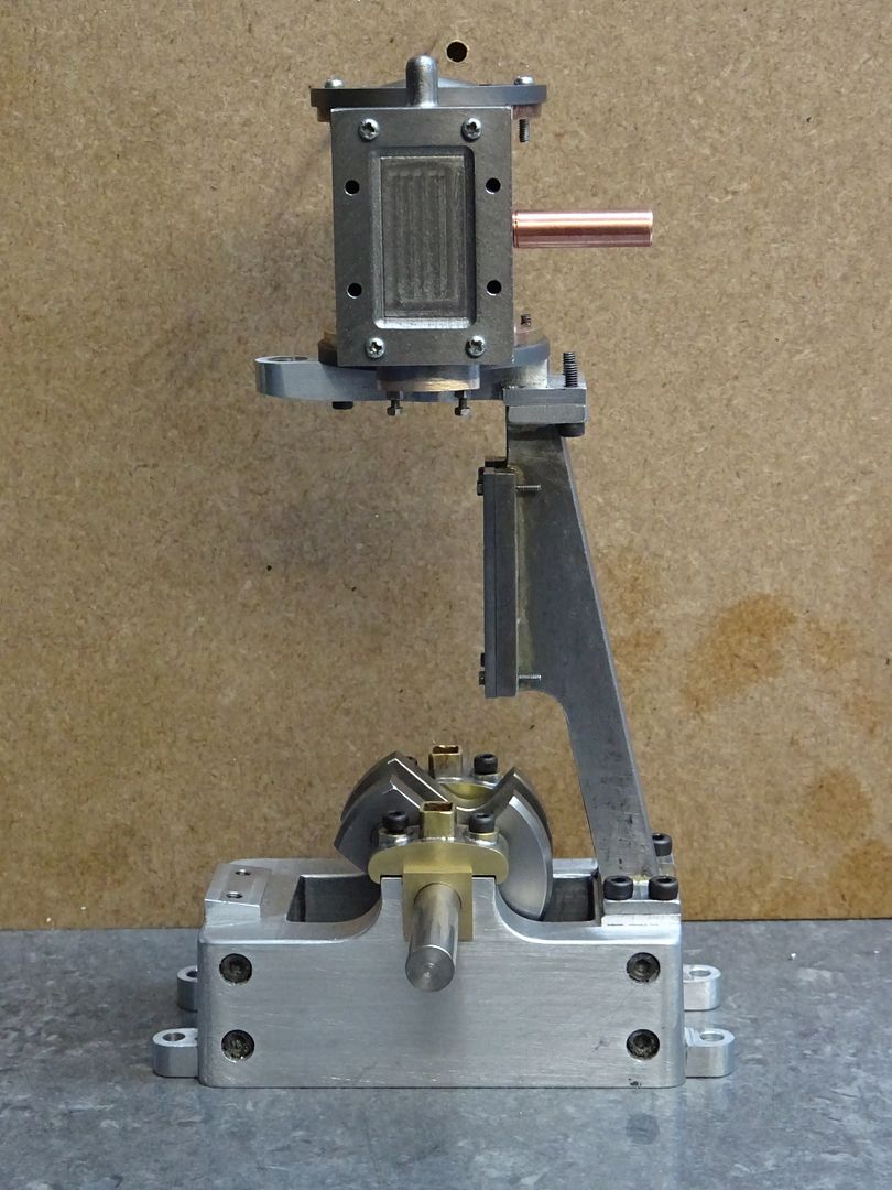
 431 forum posts 252 photos | I have a part built ST 5A that I would like to finish. Most of the machining has been done. The sole plate has already been bored out for the bearing caps and the bearings, but one of the bearing caps and one bearing are missing. I can get a new cap casting from Stuart Models but my problem is if I machine it to fit the existing seat in the sole plate and fasten it down how do I bore out the bottom of the new cap to match the existing cutout in the sole plate and still be in line with the other side ? Anyone got any suggestions? John |
| Michael Gilligan | 21/08/2019 23:54:06 |
 23121 forum posts 1360 photos | If I understand the problem correctly, John ... Make a long boring-bar, with the cutter somewhere near the middle Size the bar to act as a pilot in the complete bearing ... then bore the new cap. Probably best done 'between centres' on the lathe, with the job on the saddle. MichaelG. |
| not done it yet | 22/08/2019 07:03:02 |
| 7517 forum posts 20 photos | As above, but I think I would make new bearings after line boring both caps. My view would be that it was not worth the trouble and risk of aligning one cap to match the other - better/easier to go slightly oversize on both and be confident they were in line. Might be wrong, but that would be my preferred route. |
| Howard Lewis | 22/08/2019 12:21:06 |
| 7227 forum posts 21 photos | If you are averse to boring out the existing parent bore oversize, and making new brasses,you may be able to centre the bedplate, by mounting a piece of bar in the chuck and turning a section so that it is really snug fit in the existing parent bore and cap. It should be long enough to extend into the existing half bore, to ensure that the bedplate is aligned on the axis of the lathe. Once this alignment has been done, the cross Slide should be locked.. You can them feed your boring bar through to mount between centres, to bore the new, unmachined Cap to match the existing parent bores. This is effectively the method used in Industry when a new Main bearing Cap has to be fitted and bored for an otherwise finished Crankcase. But in this instance the machine used is a large Borer! Or if you mount a clock in the chuck, you can use this to ensure that the parent bores are correctly aligned on the centre line, before fitting the Boring Bar. If you are looking for greater precision, ensure that the present cap is tightened to the correct torque, so that is completely round. (If the torque applied differs from that used when boring originally, the bore is likely to be oval. Too low and the major axis will be in the crown, Too high and it will be across the split line ) Howard |
| JasonB | 22/08/2019 15:13:37 |
 25215 forum posts 3105 photos 1 articles | Another option steering away from the original. mill out the tow lower halves of the housings in the base to just shallow of being a square. make two new keeps from flat steel bar or give them some shape if you want to. Then make square split bearings from bar material. Bearing will stand slightly proud of base so cap can apply pressure. Saves having to bore half a hole in the cap which can deflect the tool and probably cheaper than buying cap and bearing castings from Stuarts. This sort of design
|
| John Purdy | 22/08/2019 19:32:03 |
431 forum posts 252 photos | Thanks for the replies. The ideas are somewhat like I had in mind except I hadn't thought of doing it like Jason suggests, that's very similar to the way the main bearings of the #1 and #9 are, among others. The problem I can see with boring it out between centres, or in the mill, is that you are trying to bore out a solid half circle .468" deep over a .468" deep open half circle. Obviously can't be done in one pass, (not with our machinery anyway), meaning that the boring bar plus bit has to fit through a .468" hole in the lower half, not practical on the lathe but could be done in the mill by successively increasing the dia of the sweep of the the bit in the bar and moving the bar towards the centre of the final bore. The other option I can see in the mill would be to successively remove the excess part of the upper cap with a series of increasing sizes of end mill till almost full size then use the boring bar to go through both sides increasing the bore dia slightly to ensure both are in line, and make new brasses to suit. I figured I'd be making new brasses anyway as I only have one, and have some suitable material. Of course the other much more expensive option would be to buy a new soleplate an bearing caps and start over!! ( currently 134.50 + shipping half way around the world X 1.7 to convert to Can.$) John |
| Michael Gilligan | 22/08/2019 21:59:39 |
23121 forum posts 1360 photos | Posted by John Purdy on 22/08/2019 19:32:03:
... The problem I can see with boring it out between centres, or in the mill, is that you are trying to bore out a solid half circle .468" deep over a .468" deep open half circle. Obviously can't be done in one pass, (not with our machinery anyway) ...
Would it not be possible to rough-out the new cap [using a milling cutter or a round file], leaving only a modest amount of material to bore ? MichaelG. |
| John Purdy | 22/08/2019 22:41:14 |
431 forum posts 252 photos | Yes Michael, that is what I thinking when I said in the next section of that post of mounting it on an angle plate on the mill so that it is vertical and plunging down with end mills till it is almost the right dia, then boring both sides to final dimensions. I just dug out the two series in EIM on building the engine ( the Cygnet Jun 81 and the 5A Aug 04) and noticed on a picture of the rough soleplate that the openings for the bearings are cast in as semi circles. I wonder if the caps are the same. That would make boring simple as you would be starting with a round under sized hole. John |
| Michael Gilligan | 22/08/2019 23:05:11 |
23121 forum posts 1360 photos | Posted by John Purdy on 22/08/2019 22:41:14:
Yes Michael, that is what I thinking when I said in the next section of that post of mounting it on an angle plate on the mill so that it is vertical and plunging down with end mills till it is almost the right dia, then boring both sides to final dimensions. . Apologies, John; I had missed the intention of that second part ... I thought you had rejected the idea of line-boring. [it's been a long day] MichaelG. |

Please login to post a reply.
Magazine Locator
Want the latest issue of Model Engineer or Model Engineers' Workshop? Use our magazine locator links to find your nearest stockist!
Sign up to our Newsletter
Sign up to our newsletter and get a free digital issue.
You can unsubscribe at anytime. View our privacy policy at www.mortons.co.uk/privacy
Latest Forum Posts
- *Oct 2023: FORUM MIGRATION TIMELINE*
05/10/2023 07:57:11 - Making ER11 collet chuck
05/10/2023 07:56:24 - What did you do today? 2023
05/10/2023 07:25:01 - Orrery
05/10/2023 06:00:41 - Wera hand-tools
05/10/2023 05:47:07 - New member
05/10/2023 04:40:11 - Problems with external pot on at1 vfd
05/10/2023 00:06:32 - Drain plug
04/10/2023 23:36:17 - digi phase converter for 10 machines.....
04/10/2023 23:13:48 - Winter Storage Of Locomotives
04/10/2023 21:02:11 - More Latest Posts...
- View All Topics
Support Our Partners


Shopping Partners
Subscription Offer

Latest "For Sale" Ads
- Reeves** - Rebuilt Royal Scot by Martin Evans
by John Broughton
£300.00 - BRITANNIA 5" GAUGE James Perrier
by Jon Seabright 1
£2,500.00 - Drill Grinder - for restoration
by Nigel Graham 2
£0.00 - WARCO WM18 MILLING MACHINE
by Alex Chudley
£1,200.00 - MYFORD SUPER 7 LATHE
by Alex Chudley
£2,000.00 - More "For Sale" Ads...
Latest "Wanted" Ads
- D1-3 backplate
by Michael Horley
Price Not Specified - fixed steady for a Colchester bantam mark1 800
by George Jervis
Price Not Specified - lbsc pansy
by JACK SIDEBOTHAM
Price Not Specified - Pratt Burnerd multifit chuck key.
by Tim Riome
Price Not Specified - BANDSAW BLADE WELDER
by HUGH
Price Not Specified - More "Wanted" Ads...
Get In Touch!
Do you want to contact the Model Engineer and Model Engineers' Workshop team?
You can contact us by phone, mail or email about the magazines including becoming a contributor, submitting reader's letters or making queries about articles. You can also get in touch about this website, advertising or other general issues.
Click THIS LINK for full contact details.
For subscription issues please see THIS LINK.
Digital Back Issues


Donate

 Register
 Log-in
Model Engineer Magazine
- Percival Marshall
- M.E. History
- LittleLEC
- M.E. Clock

ME Workshop
- An Adcock
- & Shipley
- Horizontal
- Mill

Subscribe Now
- Great savings
- Delivered to your door

Pre-order your copy!
- Delivered to your doorstep!
- Free UK delivery!
All Forum Topics > Workshop Techniques > Boring Problem