Forum sponsored by:

Pressure gauge help needed please.
Small pressure gauge vibrating, might destroy it, is there a damper ?
| Bob Mc | 27/04/2019 09:52:52 |
| 231 forum posts 50 photos |
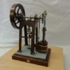
I made Mogen Kildes double diagonal engine (ME4383) which is only my second engine and fitted a small air supply valve and a pressure gauge...see picture. The engine works great and only needs a couple of pounds of pressure to get it going and I thought to put a gauge after the air supply valve in order to give some indication of what the actual air pressure was. I was expecting that the pressure gauge might fluctuate a little but I think I will have to remove it due to the needle vibrating at an alarming rate and I don't think it will last long in its present situation. Is there any kind of a damper I could make? or will it have to be removed? Can anyone help.....thanks...Bob.
|
| JasonB | 27/04/2019 10:08:13 |
 25215 forum posts 3105 photos 1 articles | A longer larger dia tube will have a damping effect, you could wind it into a coil to keep size down. However where you have it positioned will fluctuate as the valves open and close, it is better to use a pressure regulator at your compressor end and then the globe valve controls flow volume. Engine looks very well made. Edited By JasonB on 27/04/2019 10:08:54 |
| Andrew Johnston | 27/04/2019 10:23:25 |
 7061 forum posts 719 photos | Use a larger diameter pipe to the engine and a smaller diameter pipe to the pressure gauge. Andrew |
| duncan webster | 27/04/2019 10:35:58 |
| 5307 forum posts 83 photos | You need a plenum between the main pipe and the gauge, small hole in the entry (as small as you can drill it), then larger chamber with gauge screwed into it. How big is a matter of experiment, depends how small you can make the inlet Or the crude way (which I have used in my working life), put the gauge on the end of a long pipe, and carefully smack the inlet end with a hammer to restrict the entry until the gauge stops oscillating |
| mechman48 | 27/04/2019 11:00:02 |
 2947 forum posts 468 photos | Posted by JasonB on 27/04/2019 10:08:13:
A longer larger dia tube will have a damping effect, you could wind it into a coil to keep size down. However where you have it positioned will fluctuate as the valves open and close, it is better to use a pressure regulator at your compressor end and then the globe valve controls flow volume. Engine looks very well made. Edited By JasonB on 27/04/2019 10:08:54 +1.. putting a coil, or two in the line will certainly dampen the fluctuation; how about extending the gauge line round to the front, mounted on a small bracket with a coil behind the bracket? George. |
| Ian P | 27/04/2019 11:33:19 |
 2747 forum posts 123 photos | Damping pressure gauges and transducers is usually done by having a restriction in the line to the gauge. Often it is a tiny drilled orifice in what looks like a grub screw which is actually installed in the thread inlet of the gauge. The restriction does not have to be a drilled hole, a capillary tube or even a close (but not perfect fitting) diameter plug pushed into the bore of the pipe to the gauge will do the same job. Ideally the restriction should be located nearest to the source of the pulsations so that the volume of 'gas' contained within the Bourdon tube and the pipework leading up to it can act as a reservoir which evens out or damps pressure changes. Ian P
|
| Reg Rossiter | 27/04/2019 11:37:12 |
 29 forum posts | Standard marine practice is to use a needle valve before the gauge. It's merely a case of screwing the valve in until the oscillation of the pointer becomes acceptable while taking care to ensure the valve isn't shut off tight. You might get an acceptable result using a very fine orifice before the gauge instead. Reg |
| Bob Mc | 27/04/2019 12:19:20 |
| 231 forum posts 50 photos | Thanks to all....basically you are all right with the advice given! can't thank you enough ! I had already made a stand to fix the gauge on and by sheer luck I made it a cylindrical pillar, it seemed obvious to coil the small pipe around it as many turns as I could, 1/2 an hour later and I tried again.... the indicator needle was now steady... pics below.. Many thanks great people....Bob.
|
| Grindstone Cowboy | 27/04/2019 12:34:41 |
| 1160 forum posts 73 photos | A nice neat solution! |
| Bob Mc | 27/04/2019 13:21:09 |
| 231 forum posts 50 photos | I have to say thanks again...this has got to be the quickest fix I ever did! thanks to forum members advice. I now want to start another project but don't know if my skill level is up to making something more complicated or with a better level of craftmanship.... could any of you more experienced gentlemen give me your opinion based on the build of the Double Diagonal engine in the above pictures.... I really don't know what skill level I should place myself at and what project I should attempt next... nb...all the parts excepting the globe valve and pressure gauge were my own work. ...Bob...
|
| JasonB | 27/04/2019 13:33:38 |
25215 forum posts 3105 photos 1 articles | From what I said earlier you look to have made a very good job of the engine so should be able to tackle something else, I think yours looks better than the one in the mag Maybe give a short list of what you fancy doing next and we can say what may or may not suit. Edited By JasonB on 27/04/2019 13:34:21 |
| Jon Lawes | 27/04/2019 17:23:35 |
 1078 forum posts | From what I can see of your craftsmanship the world is your oyster. |
| Bob Mc | 27/04/2019 17:42:01 |
| 231 forum posts 50 photos | Thanks Jason/ John and all..... your comments have spurred me on to find something a little bit more involved to make.... will have to scour the ME mags. ...Bob.... |
| Jim Nic | 27/04/2019 18:14:25 |
 406 forum posts 235 photos | Hi Bob If you want something fairly quick there is always Jason's Jowitt engine, the complications being the shape of the cylinder block and the need to make the poppet valves and the spoked flywheels.
More complex is the Corliss type engine, free plans from Model Engine Makers website. Complications are the operation of the valves and making the flywheel. Everything else should be a breeze for you.
My last suggestion depends on your budget. The Eastern & Anderson Grasshopper model from a castings set available from Polly Models for about £240 I believe.
Hope this has given you something to consider Jim
|
| vintage engineer | 27/04/2019 21:54:56 |
 293 forum posts 1 photos | You need to fit a snubber. |
| JasonB | 28/04/2019 07:08:50 |
25215 forum posts 3105 photos 1 articles | The Easton and Anderson does not need to be done from castings if you prefer barstock. This one should be in ME shortly, another barstock engine except the flywheel.
|


Please login to post a reply.
Magazine Locator
Want the latest issue of Model Engineer or Model Engineers' Workshop? Use our magazine locator links to find your nearest stockist!
Sign up to our Newsletter
Sign up to our newsletter and get a free digital issue.
You can unsubscribe at anytime. View our privacy policy at www.mortons.co.uk/privacy
Latest Forum Posts
- *Oct 2023: FORUM MIGRATION TIMELINE*
05/10/2023 07:57:11 - Making ER11 collet chuck
05/10/2023 07:56:24 - What did you do today? 2023
05/10/2023 07:25:01 - Orrery
05/10/2023 06:00:41 - Wera hand-tools
05/10/2023 05:47:07 - New member
05/10/2023 04:40:11 - Problems with external pot on at1 vfd
05/10/2023 00:06:32 - Drain plug
04/10/2023 23:36:17 - digi phase converter for 10 machines.....
04/10/2023 23:13:48 - Winter Storage Of Locomotives
04/10/2023 21:02:11 - More Latest Posts...
- View All Topics
Support Our Partners


Shopping Partners
Subscription Offer

Latest "For Sale" Ads
- Reeves** - Rebuilt Royal Scot by Martin Evans
by John Broughton
£300.00 - BRITANNIA 5" GAUGE James Perrier
by Jon Seabright 1
£2,500.00 - Drill Grinder - for restoration
by Nigel Graham 2
£0.00 - WARCO WM18 MILLING MACHINE
by Alex Chudley
£1,200.00 - MYFORD SUPER 7 LATHE
by Alex Chudley
£2,000.00 - More "For Sale" Ads...
Latest "Wanted" Ads
- D1-3 backplate
by Michael Horley
Price Not Specified - fixed steady for a Colchester bantam mark1 800
by George Jervis
Price Not Specified - lbsc pansy
by JACK SIDEBOTHAM
Price Not Specified - Pratt Burnerd multifit chuck key.
by Tim Riome
Price Not Specified - BANDSAW BLADE WELDER
by HUGH
Price Not Specified - More "Wanted" Ads...
Get In Touch!
Do you want to contact the Model Engineer and Model Engineers' Workshop team?
You can contact us by phone, mail or email about the magazines including becoming a contributor, submitting reader's letters or making queries about articles. You can also get in touch about this website, advertising or other general issues.
Click THIS LINK for full contact details.
For subscription issues please see THIS LINK.
Digital Back Issues


Donate

 Register
 Log-in
Model Engineer Magazine
- Percival Marshall
- M.E. History
- LittleLEC
- M.E. Clock

ME Workshop
- An Adcock
- & Shipley
- Horizontal
- Mill

Subscribe Now
- Great savings
- Delivered to your door

Pre-order your copy!
- Delivered to your doorstep!
- Free UK delivery!
All Forum Topics > Beginners questions > Pressure gauge help needed please.