Forum sponsored by:

Myford top slide cone damage.
| Adrian 2 | 27/01/2018 17:53:17 |
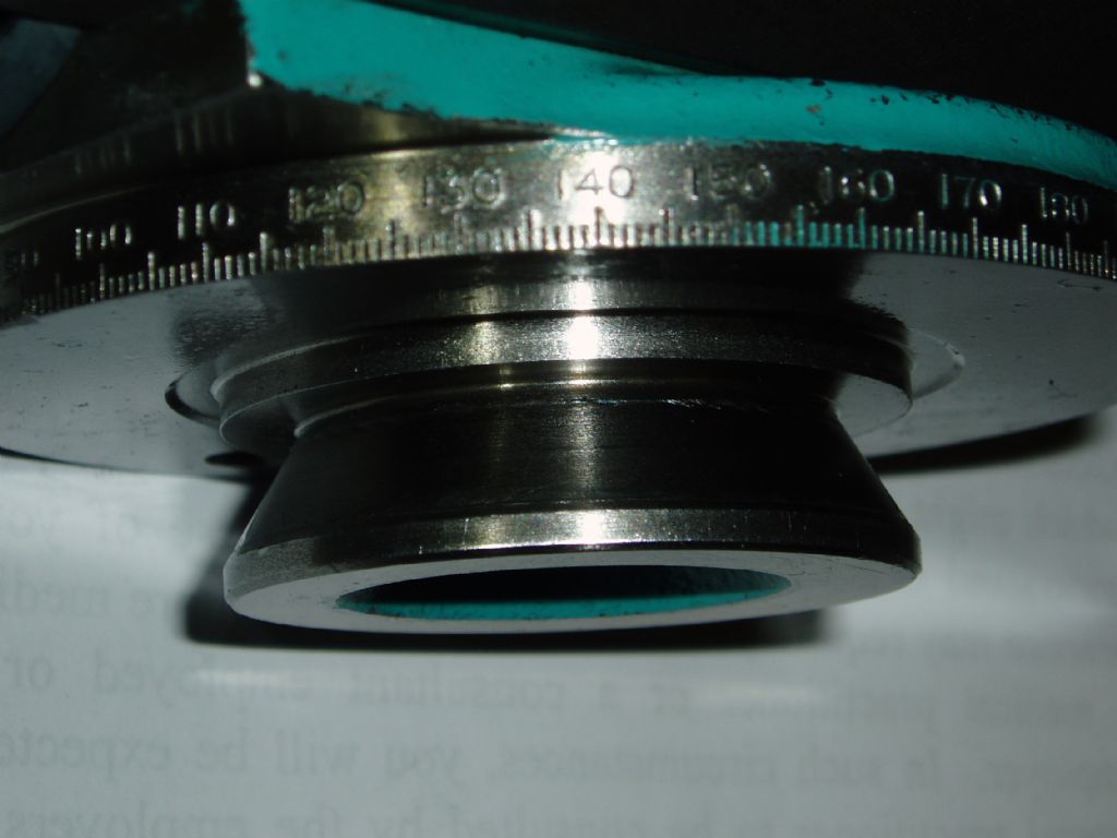
| 104 forum posts 19 photos | I am gradually bonding with my "new to me" big bore super 7. I have noticed an increasing number of bruise/digging in marks on the cone on the underside of the top slide base where the locking thrust pads bear. As noted in a previous thread these pads are handed and profiled to conform to the shape of the cone. The damage seems to be caused by the right hand pad's extreme tip digging in and to a lesser extent it's shortest point ( just visible in the pictures). The main contact surface of the pad does not make contact at all. I think they may be hardened so not easy to fettle. Has anyone else experienced this type of damage here? Am thinking of making maybe brass pads and blueing and fitting the ends to conform properly to the cone. A new RH pad from Myford makes no difference. The new pads incidentally , are tapped for extraction. Good idea. Thank you, Adrian.
|
| Nick Hulme | 27/01/2018 18:13:18 |
| 750 forum posts 37 photos | This might be best posted somewhere other than the 3D Printers and 3D Printing" area of the forum, but while you're here have you considered engineer's blue and scraping them to conform? My 30.5mm spindle bore Super 7 is at least 60 years old and I've never noticed any marks that cause me concern on the conical section, I'll have a closer look next time I take it off, - Nick Edited By Nick Hulme on 27/01/2018 18:13:46 |
| Adrian 2 | 27/01/2018 18:26:44 |
| 104 forum posts 19 photos | Thanks Nick, I have considered fitting them but I think they will be hard. I didn't know I had posted this in the wrong section. Oops ! Adrian. |
| Neil Wyatt | 27/01/2018 18:47:23 |
 19226 forum posts 749 photos 86 articles | Moved |
| Adrian 2 | 27/01/2018 19:03:05 |
| 104 forum posts 19 photos | Thanks Neil. |
| Neil Lickfold | 27/01/2018 19:21:48 |
| 1025 forum posts 204 photos | You will need to refit them. Depending on how they are. If you can share a picture of the pusher parts, the bits that push onto the cone, then better advice can be given. Sometimes it is small things like a bur from manufacturing etc or an edge that is not rounded etc. Neil |
| Tony Pratt 1 | 27/01/2018 19:23:02 |
| 2319 forum posts 13 photos | Have they been put back in the wrong holes? Tony |
| Adrian 2 | 27/01/2018 19:53:08 |
| 104 forum posts 19 photos | I don't think so Tony, the LH pad conforms quite well to the cone and a new replacement RH is no better than my original. The damage concerns me and I wondered if others had suffered this problem. The cure no doubt is closely conforming pads. Neil, the LH pad bears a pretty good contact witness mark. I need to achieve the same on the RH pad. Thank you both for your replies. Adrian. |
| Hopper | 28/01/2018 06:14:29 |
 7881 forum posts 397 photos | I didn't see your previous thread and can't tell much from your pic above, but I'd be surprised if the pads are hardened. Seems unnecessary in a low-wear application like this, and usually a hardened surface will not grip as well as a softer one. And normal design practice would be to make the replaceable pads softer than than the more valuable cone on the main piece. If it were me, I'd have a go at filing the tips of the clamping pads to match the shape of the cone, and make sure to round off any sharp edges that might dig into the cone. If the problem persisted, or if the pads were hardened, I reckon I would be making brass ones to fit. Unless there is some specific reason Myford would make these pads hardened? Edited By Hopper on 28/01/2018 06:16:10 |
| Michael Gilligan | 28/01/2018 06:37:38 |
 23121 forum posts 1360 photos | This previous thread may be worth a look: **LINK** http://www.model-engineer.co.uk/forums/postings.asp?th=129986&p=1 MichaelG. Edited By Michael Gilligan on 28/01/2018 06:38:29 |
| Adrian 2 | 28/01/2018 07:40:19 |
| 104 forum posts 19 photos | Thank you Hopper for your thoughts on this. I will see if they are hardened and go from there, I don't see this as a major problem but having noticed the marking taking place I want to put a stop to it. Michael G, your link is the thread I referred to in my opening post. Thank you. Adrian. |
| Michael Gilligan | 28/01/2018 07:54:07 |
23121 forum posts 1360 photos | The offset of the two clamps from the centre of top-slide rotation will obviously prescribe the required profile, but I have not seen that dimension stated. ... any offers ? MichaelG. . Note: the offset is quite evident in this video [about scraping the flat surfaces of the cross-slide] : https://m.youtube.com/watch?v=D0aEaf5gdu0
Edited By Michael Gilligan on 28/01/2018 07:57:12 |
| Michael Gilligan | 28/01/2018 07:56:40 |
23121 forum posts 1360 photos | Posted by Adrian 2 on 28/01/2018 07:40:19:
Michael G, your link is the thread I referred to in my opening post. . Adrian, Yes, that was my assumption ... the link was for Hopper's benefit. MichaelG. |
| Hopper | 28/01/2018 07:58:27 |
7881 forum posts 397 photos | Posted by Michael Gilligan on 28/01/2018 06:37:38:
This previous thread may be worth a look: **LINK** http://www.model-engineer.co.uk/forums/postings.asp?th=129986&p=1 MichaelG. Edited By Michael Gilligan on 28/01/2018 06:38:29 Ah, yes, possibly hardened to prevent mushrooming under repeated use, maybe? If that is the case, the cure would be to grind them to fit the taper shape using bearing blue and a Dremel type grinder etc. I do like the idea mentioned of taper pinning so over-tightening of the clamp screws is eliminated, along with concurrent warping of the slides etc.
|
| Adrian 2 | 28/01/2018 09:35:16 |
| 104 forum posts 19 photos | I can confirm they are hardened. Adrian. |
| KWIL | 28/01/2018 10:48:06 |
| 3681 forum posts 70 photos | Two points to note. The pads should be a good sliding fit in their respective bores, this will enable the pads to rotate to match the cone at the point of contact. When tightening, approach the pinch point gently, this will give the pads ends a chance of proper alignment. Making pads is a simple exercise, you can make a jig with the offset in the correct place and a means of radially securing the blanks, the jig main bore is a taper of the same angle of the topside cone. For a previous project I had to make such an item for a different cone angle, pads matched perfectly. |
| Adrian 2 | 28/01/2018 16:36:35 |
| 104 forum posts 19 photos | I like the sound of that KWIL. Thank you Adrian. |
| KWIL | 30/01/2018 17:40:22 |
| 3681 forum posts 70 photos | Adrian 2, you have a PM. |
| Neil Lickfold | 30/01/2018 18:45:19 |
| 1025 forum posts 204 photos | So you can get a dremel or similar, and use bearing blue, and just keep trying and grinding the areas that are touching. Eventually it will be a nice even blue every where. It is either that or making a fixture to grind it to the form of the taper cone. With a bit of experience you get to read the blue and how much to take off at a time and where to blend to etc. GUD bearing blue is very good for this. The thin ones like dykim? dykum? are difficult to read when you have more than 0.001 inches to remove, but is good when you want to be in the tenth's of a thou. Getting a little magnet and gluing to a kebab scure works well for removing such items.
|

Please login to post a reply.
Magazine Locator
Want the latest issue of Model Engineer or Model Engineers' Workshop? Use our magazine locator links to find your nearest stockist!
Sign up to our Newsletter
Sign up to our newsletter and get a free digital issue.
You can unsubscribe at anytime. View our privacy policy at www.mortons.co.uk/privacy
Latest Forum Posts
- *Oct 2023: FORUM MIGRATION TIMELINE*
05/10/2023 07:57:11 - Making ER11 collet chuck
05/10/2023 07:56:24 - What did you do today? 2023
05/10/2023 07:25:01 - Orrery
05/10/2023 06:00:41 - Wera hand-tools
05/10/2023 05:47:07 - New member
05/10/2023 04:40:11 - Problems with external pot on at1 vfd
05/10/2023 00:06:32 - Drain plug
04/10/2023 23:36:17 - digi phase converter for 10 machines.....
04/10/2023 23:13:48 - Winter Storage Of Locomotives
04/10/2023 21:02:11 - More Latest Posts...
- View All Topics
Support Our Partners


Shopping Partners
Subscription Offer

Latest "For Sale" Ads
- Reeves** - Rebuilt Royal Scot by Martin Evans
by John Broughton
£300.00 - BRITANNIA 5" GAUGE James Perrier
by Jon Seabright 1
£2,500.00 - Drill Grinder - for restoration
by Nigel Graham 2
£0.00 - WARCO WM18 MILLING MACHINE
by Alex Chudley
£1,200.00 - MYFORD SUPER 7 LATHE
by Alex Chudley
£2,000.00 - More "For Sale" Ads...
Latest "Wanted" Ads
- D1-3 backplate
by Michael Horley
Price Not Specified - fixed steady for a Colchester bantam mark1 800
by George Jervis
Price Not Specified - lbsc pansy
by JACK SIDEBOTHAM
Price Not Specified - Pratt Burnerd multifit chuck key.
by Tim Riome
Price Not Specified - BANDSAW BLADE WELDER
by HUGH
Price Not Specified - More "Wanted" Ads...
Get In Touch!
Do you want to contact the Model Engineer and Model Engineers' Workshop team?
You can contact us by phone, mail or email about the magazines including becoming a contributor, submitting reader's letters or making queries about articles. You can also get in touch about this website, advertising or other general issues.
Click THIS LINK for full contact details.
For subscription issues please see THIS LINK.
Digital Back Issues


Donate

 Register
 Log-in
Model Engineer Magazine
- Percival Marshall
- M.E. History
- LittleLEC
- M.E. Clock

ME Workshop
- An Adcock
- & Shipley
- Horizontal
- Mill

Subscribe Now
- Great savings
- Delivered to your door

Pre-order your copy!
- Delivered to your doorstep!
- Free UK delivery!
All Forum Topics > Manual machine tools > Myford top slide cone damage.