Forum sponsored by:

Taper attachment
| Thomas Staubo | 15/08/2017 13:10:18 |
 54 forum posts | I had an idea about making a taper attachment for my Myford ML7 from some linear rail. At first I contemplated using the round "Thompson rod" like this:
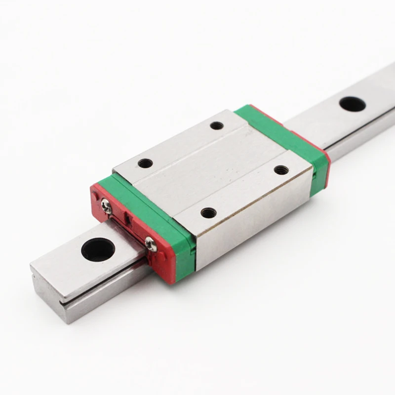
But then I saw the ones with lower profile, like the MGN15, and I think they are stiffer for their size :
It has been done before. Here's a cuemaker that made a quite long one. And it doesn't seem too difficult to make, and the linear rails are cheap from China.
I'm not sure how long to make it though, I think a bit longer than the original one would be nice. Does anyone here know the travel of the original Myford taper attachment? And how large angles should I aim for? Is 10 degrees too much?
|
| Hopper | 15/08/2017 13:53:38 |
 7881 forum posts 397 photos | I've been playing with the same idea since viewing a 20mm round linear slide like in your first pic, at a mate's place. The 20mm round one looks to be more than solid enough for purpose. It was about 400mm long, which also looked ideal. I should think 10 degrees either way would be enough movement. Morse tapers are only about 3 degrees inclusive, or 1.4 per side. 10 degrees, from memory, is what the Myford ones have. As for length, well it depends on what you will use it for. Morse tapers? All under six inches long unless you get way out of Model Engineer typical sizes. A 400mm linear slide would give about 300mm of useful movement, allowing 50mm per end for the width of the slider. I can't think of any tapered jobs I would want to do that would be longer than that. GH Thomas in his book "Model Engineers Workshop Manual" has a good design for a worm wheel type micrometer adjustment to go on one end of the moveable part of the attachment, giving precise fine adjustment, rather than Myford's hit and miss by the marks system. But GHT's addition requires making a hob to hob gear teeth on a large radius on one end of the moving part (the linear guide) and turning a worm to match. |
| Brian Wood | 15/08/2017 15:35:15 |
| 2742 forum posts 39 photos | Thomas, I based the one I made on 18 mm diameter hydraulic ram. Straight as a die, heavy chrome plate to resist corrosion and made from decent steel that resists bending. The slider is a simple lump of aluminium about 3 inches long with felt wipers at each end to keep debris out. I can.t remember all the details now, but I'm pretty sure I gave it +/- 10 degrees or so in either direction with a detachable fine setting on the tail stock end. It is supported on outriggers built out from the base of the lathe. Setting of angles is greatly simplified by having a DRO on the lathe. It does though run the full length of the bed, why make it any differently? Regards Brian
|
| Robbo | 15/08/2017 15:45:09 |
| 1504 forum posts 142 photos | Thomas The moving base of the Myford taper turning attachment is 11¼"long, and the "rail" on which the saddle slides is 9¼" long. So given some "underlap" at the saddle ends, the centre point of the saddle moves probably 8½ - 8¾" in total, which is plenty for the usual Morse taper type of work.. The moving base is pivoted at the centre, and moves 10 degrees either side of centre at the end, as Hopper says. At this length 10 degrees equates to 1" of movement. As an aside, instead of using Myford's hit and miss (literally, tap it with a hammer) method of adjustment I have a micrometer thimble mounted at one end of the fixed base to push the moving base around the degree scale. GH Thomas' design mentioned by Hopper is wonderful, but given the number of times the attachment is used is overkill for me. |
| Clive Foster | 15/08/2017 15:48:17 |
| 3630 forum posts 128 photos | Had similar thoughts for my Smart & Brown 1024 before a factory fit unit turned up at almost two winces price. Linear rails is over-thinking it and probably not the best way in practice as its vertically constrained so needs to be properly level with the bed in both planes. Any tilt may affect how well it works. Taper attachments need to be shake free but really free moving as any binding tends to tilt, twist or lift the carriage. Found out that the hard way with a SouthBend Heavy 10. No hold down gibs on the front shears so any drag from the taper attachment would twist the carriage slightly amusing it to rise on the front Vee just enough to mess up the job. Taper attachments are way out the back of the lathe so plenty of leverage. Standard method on high class lathes is a simple U channel with a slider running in it. Gib or sliding taper arrangement inside the slide to get a really nice sliding fit. Simples. Screw adjustment is normal with ruled marks and, sometimes, a vernier for setting. Hafta cut and try for anything really accurate so GHT, for once, let his passion for nicely correct engineering overcome logic. Were I building one I'd just fit a push screw at each end with either a micrometer head or dial gauge to set / measure travel. Either is cheap enough these days and only one is needed. Just mount on the appropriate end and zero before use. Needs zero setting pins to lock the taper unit straight ahead of course. ± 10° seems pretty standard range so I guess thats a good one to go for. Over that sort of angle micrometer or dial gauge movement will be close to linear so a simple table of readings against angle will suffice. As the micrometer or dial gauge will only be reading one way setting it at 5° off perpendicular to the straight ahead position makes it closer to truly linear improving the accuracy of interpolation between table values. Clive. PS Brian and Robbo type faster. Edited By Clive Foster on 15/08/2017 15:49:14 |
| Baz | 15/08/2017 16:09:39 |
| 1033 forum posts 2 photos | Easiest way of setting up a taper turn attachment is with slips and sine bar. All you need to do is clock the sine bar parallel to lathe saddle and the angle is spot on. |
| Raglan Littlejohn | 15/08/2017 16:56:32 |
| 30 forum posts 21 photos | This looks an excellent idea from Thomas. MGM12 400mm linear rail including one linear rail block is £16.56 from Banggood. Additional blocks are £6.30. I would be tempted to use two blocks. They should be low friction, smooth running, and accurately made. This will save a lot of machining work in making a taper attachment, the main parts needed will be a platform, a couple of brackets to fit to the lathe bed, and a bracket to connect the cross slide to the linear blocks. As long as you make sure the blocks cannot tilt in use, I cannot see any problems. |
| Neil Wyatt | 15/08/2017 17:07:47 |
 19226 forum posts 749 photos 86 articles | Posted by Hopper on 15/08/2017 13:53:38:
GH Thomas in his book "Model Engineers Workshop Manual" has a good design for a worm wheel type micrometer adjustment to go on one end of the moveable part of the attachment, giving precise fine adjustment, rather than Myford's hit and miss by the marks system. But GHT's addition requires making a hob to hob gear teeth on a large radius on one end of the moving part (the linear guide) and turning a worm to match. GHT was a master of over-solutioneering. A simple thumb-screw adjuster on a piece of accurate studding would have given a tiny error. If it was set to be correct for 1 degree either way, the error at 5 degrees either way would be 2 parts in a thousand. Neil (Puts on tin hat, and sits in tin bath) |
| Clive Foster | 15/08/2017 17:24:30 |
| 3630 forum posts 128 photos | Baz Starting a post with "Easiest way ..." is bravery beyond the call of duty (worthy of a CDM at least) as "easiest" is so dependent on what equipment you have and, often, constructional details of your particular machine. For my money the "most effective with minimal equipment" way to set a taper turning attachment requires a fixed length spacer and bed-stop with an indicator to measure actual sideways shift over a fixed length. Needs a parallel bar in chuck, collet or headstock taper to run the clock along of course It's frequently possible to use the part you are going to put the taper on as its own reference. Probably making a virtue of necessity but should your chuck or machine be a touch out of line using the turned to starting size workpiece as a reference in that manner incorporates most machine errors into the taper setting. Crudest "but works" implementation I ever saw used a toolmakers clamp for the bed stop and a short piece of conduit tube with a bung in one end and a threaded joining sleeve with blanking plug at the other so it could be adjusted to the precise length. Spacer and bed stop method makes life easy when following taper per foot and similar style references. Raglan When using those ball bearing carrier linear rails its important to stay within the vertical taper tolerance. I know from previous experience that the high end ones get quite unhappy if there is more than a smidgin of uphill or downhill tilt. I imagine the affordable ones suffer similarly. Great thing with the open U channel is that ordinary careful workmanship is more than close enough for end to end tilt. If its touch out sideways 'tis no great difficulty to put a small tilt compensation capability into the post assembly joining the cross slide to the slider. Clive. Edited By Clive Foster on 15/08/2017 17:26:42 |
| Raglan Littlejohn | 15/08/2017 21:16:32 |
| 30 forum posts 21 photos | Clive, I understand your concern re using the ball bearing carrier linear rail in this application. It's a pity they are so sensitive to tilting. I guess they are designed to fit under a moving table (typical application, cnc router), so most of the force is from above, not from the side. Looking at the link in the first post, http://www.dzcues.com/taper_bar.html, I see he uses a Heim link to compensate for vertical misalignment. He also looks to be using a high end carrier. As you suggest,the u channel carefully made looks the best solution. John. |
| Robbo | 15/08/2017 21:22:28 |
| 1504 forum posts 142 photos | Quote " Clive. PS Brian and Robbo type faster." But Brian types faster than Robbo - or presses Enter sooner! |
| Neil Wyatt | 15/08/2017 23:20:25 |
19226 forum posts 749 photos 86 articles | As all the forces are in the same direction, why not use an LM6UU bearing as used on 3D printers? OIne would be working under optimum conditions in this role. |
| Clive Foster | 16/08/2017 01:08:20 |
| 3630 forum posts 128 photos | Sorry Neil but the LM6UU is quite the wrong type of bearing for this role. Firstly it can only be used with end mountings for the shaft which, even if of substantially larger diameter than the 6 mm used with this bearing, won't be strong enough to guide the cross-slide to produce a straight taper. Secondly you still have the uphill - down hill tilt constraint. Bad enough to align if you opt for a fixed support bracket. Normal practice is to make "carried on a bracket off the back of the bed" attachments moveable either with a tee slot or multiple sets of mounting holes. You pretty much have to make them moveable as one the full length of the bed becomes unfeasibly large. Its rare to see ones with taper slide bars seriously longer than a foot or so. Using a taper setting bar system that requires close control of vertical position and lengthways tilt makes manufacture, installation and adjustment unnecessarily difficult. It's different for the other style of taper attachment which is mounted directly to the back of the saddle and moves with it. These are normally made with upper and lower dovetail slides. Upper one being the taper setting bar and the lower one a guide bar tied to the bed by a fairly long rod connected to a clamp. In normal operation the bed clamp is loose so the whole kit & caboodle moves up and down the bed with the saddle. Fixing the clamp allows taper operation once the other setting up jobs have been done. Always seemed and unnecessarily complex, unavoidably expensive and tricky to set-up system to me. Practical experience with Churchill Cub (I think) and SouthBend Heavy 10 lathes did nothing to mollify my feelings. Linear bearing rails would work well in this layout as the major problem is getting the two slides adjusted for smooth, shake free, nominal zero play movement with minimal friction. All too easy to end up with excessive friction on dovetail slides leading. The tilt issues are still important but confining the mechanics to a single unit permanently affixed to the saddle makes life easier. Theoretically there should be tilt compensation built into the tie-bar and clamp assembly. In practice the tie bar is made fairly long giving a small amount of inherent flexibility which suffices to cope with any variations providing the taper turning attachment is accurately installed. For a well made machine the relevant parts of the bed and saddle will be in pretty accurate alignment anyway. Clive.
|
| Mark Rand | 16/08/2017 01:45:25 |
| 1505 forum posts 56 photos | Umm, the uphill/downhill tilt thing is a non-issue. One can use a vertical-pin-in-a-hole connecting the cross slide to the taper attachment, such as used on the Myford one or one could use a flexure if one were that way inclined (or other accommodations). Front/back tilt is no different for a linear rail than for a parallel (Hardinge) or dovetail (Myford) attachment. If you can't get it aligned, use a ball joint. I'm not sure that there is any advantage in using a linear rail compared with a sliding way, given that friction isn't a major problem and that slack/clearance can be made miniscule by proper construction.
I do have a taper attachment on my ML7 that I've used once in ten years. To be honest, it gets in the way when I oil the carriage... On the Hardinge HLV, I've thought about making a taper attachment similar to the Hardinge ones (the Hardinge lathes have the cross slide slotted for the feed screw, which means that a taper attachment only needs one nut to be loosened to free the cross slide from the feed screw). I've also got a length of linear rail and carriages that I inherited from work, but I'm not sure that it would give any benefits compared with a sliding shoe and gibs. |
| Hopper | 16/08/2017 12:51:33 |
7881 forum posts 397 photos | Nice set of drawings and article here **LINK** for a shop-made taper turning attachment, using a piece of round bar in a manner similar to the linear slide unit in the first pic. Looks like they made the movement in the 12" range. Could be of some help if you are designing your own. |
| Hopper | 16/08/2017 13:07:20 |
7881 forum posts 397 photos | Posted by Neil Wyatt on 15/08/2017 17:07:47:
GHT was a master of over-solutioneering. That's what makes his stuff so interesting, LOL. I have finally got the Versatile Dividing Head to the stage where I am ready to drill the several hundred holes in the three index plates, every single hole in every single circle individually placed by using the second worm and wheel "micro adjustment" fitting, thus locating each hole within one thousandth of a degree. Nice to know, but really... |
| Clive Foster | 16/08/2017 14:17:32 |
| 3630 forum posts 128 photos | Could do a lot worse than copying the layout of my Smart and Brown 1024 taper turner. This uses an accurately finished 2" wide by 7/8" thick rectangular steel bar as the guide with a hefty U shape steel slider running on it. S & B make a nice machining job of the slider and fit a taper gib to set the clearances just so. For home shop version the slider can be seriously simplified by making it a decently hefty flat plate (1/2" thick perhaps?) with four ordinary ball bearings fitted on suitable pins to run along the guide bar. Two each side. Make the pins on one side eccentric so the bearings can be set just right against the guide bar. I'd probably push the boat out and use self aligning bearings producing a unit essentially impervious to small tilt errors. Bind free operational tilt tolerance of any constrained linear guideway system is pretty much an absolute value. So if two guide systems have to run together the further apart they are and the longer the travel the more accurate you have to be. Typically the fixed to the back of the bed taper turning units have travels from around 8 to 24 inches horizontally. If you have vertical constraint on the guideway it needs to be co-linear with the bed to better than the tilt tolerance over the travel distance. Not something to get involved with from choice. Especially as the bracket is usually L shaped with two sets of alignments inches apart and in different planes getting in on the act. Hopper Nice link but absolutely not one to copy. It is a "simplification" of the one SouthBend used on the Heavy 10 and promises to be a complete and utter pain in the butt to get aligned and working properly. Even the factory fit SouthBend version requires patience, understanding, cold towels, aspirin, a locked shop door with a barbed wire not disturb for anything sign if you are to get it working really well. Mine had been set-up to the previous owners idea of nice (!) whilst proudly showing off how many "you won't believe anyone could get things wrong this way" skills he had mastered. Had several hour or two goes at sorting it in situ ending up at sort of OK standard but eventually bowed to the inevitable, took it off and spent an afternoon getting it right, dead right. As with so many set-up things first time is a nightmare but once you have done three or four and got the method dialled in you start wondering what all the fuss was about. As ever you don't realise how poor sort of OK is until you encounter just right. Once sorted it could routinely produce tapers that were straight and true with barely a flicker of a tenths thou indicator and a surface finish of good grinder standard. At sort of OK standard a decent morse was just about possible but you really had to baby it and operate it just right or a few tenths hollow or crown somewhere along it was certain. About the only decent thing about that layout is that the two bar type sliding bearings are very closely coupled so its pretty much immune to tilt error induced binding if made to decent standard. Clive.
Edited By Clive Foster on 16/08/2017 14:18:08 Edited By Clive Foster on 16/08/2017 17:08:33 |
| Bazyle | 16/08/2017 15:12:09 |
 6956 forum posts 229 photos | If you use a round bar type and turn one end very slightly eccentric you can arrange to rotate the bar to adjust the taper. |
| Aaron Frederick | 24/08/2017 15:26:42 |
| 3 forum posts 1 photos | I recently purchased just a standard issue Myford taper turning attachment for my Super 7 lathe and I have a general question that probably doesn't warrant its own thread. It is a power cross-feed model, and I am wondering what would be the best way to disengage the cross-slide to allow me to use the attachment? Would removing the cross-slide front bracket disengage it completely and free the cross-slide completely? Or do I need to also unscrew the feed-nut partially? I don't have the attachment yet, probably will work it out when I've got it but some advice would be appreciated if anyone could help.
Edited By Aaron Frederick on 24/08/2017 15:27:01 |
| Tony Pratt 1 | 24/08/2017 15:31:51 |
| 2319 forum posts 13 photos | I just remove the 2 cap head screws holding the bracket onto the cross slide & wind the screw outwards if necessary to clear any movement of the cross slide when being driven by the attachment. Tony |


Please login to post a reply.
Magazine Locator
Want the latest issue of Model Engineer or Model Engineers' Workshop? Use our magazine locator links to find your nearest stockist!
Sign up to our Newsletter
Sign up to our newsletter and get a free digital issue.
You can unsubscribe at anytime. View our privacy policy at www.mortons.co.uk/privacy
Latest Forum Posts
- hemingway ball turner
04/07/2025 14:40:26 - *Oct 2023: FORUM MIGRATION TIMELINE*
05/10/2023 07:57:11 - Making ER11 collet chuck
05/10/2023 07:56:24 - What did you do today? 2023
05/10/2023 07:25:01 - Orrery
05/10/2023 06:00:41 - Wera hand-tools
05/10/2023 05:47:07 - New member
05/10/2023 04:40:11 - Problems with external pot on at1 vfd
05/10/2023 00:06:32 - Drain plug
04/10/2023 23:36:17 - digi phase converter for 10 machines.....
04/10/2023 23:13:48 - More Latest Posts...
- View All Topics
Support Our Partners


Shopping Partners
Subscription Offer

Latest "For Sale" Ads
- Reeves** - Rebuilt Royal Scot by Martin Evans
by John Broughton
£300.00 - BRITANNIA 5" GAUGE James Perrier
by Jon Seabright 1
£2,500.00 - Drill Grinder - for restoration
by Nigel Graham 2
£0.00 - WARCO WM18 MILLING MACHINE
by Alex Chudley
£1,200.00 - MYFORD SUPER 7 LATHE
by Alex Chudley
£2,000.00 - More "For Sale" Ads...
Latest "Wanted" Ads
- D1-3 backplate
by Michael Horley
Price Not Specified - fixed steady for a Colchester bantam mark1 800
by George Jervis
Price Not Specified - lbsc pansy
by JACK SIDEBOTHAM
Price Not Specified - Pratt Burnerd multifit chuck key.
by Tim Riome
Price Not Specified - BANDSAW BLADE WELDER
by HUGH
Price Not Specified - More "Wanted" Ads...
Get In Touch!
Do you want to contact the Model Engineer and Model Engineers' Workshop team?
You can contact us by phone, mail or email about the magazines including becoming a contributor, submitting reader's letters or making queries about articles. You can also get in touch about this website, advertising or other general issues.
Click THIS LINK for full contact details.
For subscription issues please see THIS LINK.
Digital Back Issues


Donate

 Register
 Log-in
Model Engineer Magazine
- Percival Marshall
- M.E. History
- LittleLEC
- M.E. Clock

ME Workshop
- An Adcock
- & Shipley
- Horizontal
- Mill

Subscribe Now
- Great savings
- Delivered to your door

Pre-order your copy!
- Delivered to your doorstep!
- Free UK delivery!
All Forum Topics > Workshop Tools and Tooling > Taper attachment