Forum sponsored by:

Boring Bar Holder
In MEW 240, April 2016, Alistair Sinclair revisits an old design by D.H. Downie.
Articles
A Heavy Duty Boring Bar Holder
In MEW 240, April 2016, Alistair Sinclair revisits an old design by D.H. Downie.
| Neil Wyatt | 14/03/2016 13:01:32 |
 19226 forum posts 749 photos 86 articles | In MEW 240, April 2016, Alistair Sinclair revisits an old design by D.H. Downie. An email to the Editor in the January Scribe a Line (MEW No 237) from David Byways asking for his help caught my attention concerning a boring bar tool holder illustrated in issue 235, pages 64 and 66. The query elicited a reply from Ian Strickland which referred David to an article in Model Engineer issues 3465 and 3466 from 1973. These contained an article by D H Downie giving details of just such a tool post. In You can download D.H Downie's article HERE. Neil |
| Michael Gilligan | 14/03/2016 14:06:09 |
 23121 forum posts 1360 photos | Well done, Neil That looks a very useful piece of kit. MichaelG. |
| Neil Wyatt | 14/03/2016 14:17:36 |
19226 forum posts 749 photos 86 articles | Congratulations should go to David, Alistair and Ian for digging it out! Neil |
| Michael Gilligan | 14/03/2016 15:25:12 |
23121 forum posts 1360 photos | O.K.
|
| JasonB | 14/03/2016 15:31:20 |
 25215 forum posts 3105 photos 1 articles | I kind of wonder if its worth making a "heavy duty" holder and then putting a spindly 3/8" bar in it, even the larger 5/8" one is not exactly heavy unless the standard Myford topslide and toolpost is that flexible? Or am I missing something? |
| Jon Gibbs | 14/03/2016 17:24:48 |
| 750 forum posts | Posted by JasonB on 14/03/2016 15:31:20:
I kind of wonder if its worth making a "heavy duty" holder and then putting a spindly 3/8" bar in it, even the larger 5/8" one is not exactly heavy unless the standard Myford topslide and toolpost is that flexible? Or am I missing something? Probably not but all things are relative I think the limiting factor in this setup on the diameter of boring bar is the hole through the "plug" which is 3/4" in the drawing but even a 5/8" boring bar on the old ML7 would be tricky thing to hold otherwise. Jon |
| Ajohnw | 14/03/2016 17:59:38 |
| 3631 forum posts 160 photos | I posted a shot of one of those some time ago on here
It's what I use for a 16mm boring bar but it will take smaller. It's boxford height. I need it because my qctp takes standard myford sized holder and even though a boring bar sits either side of the spindle axis they don't make a holder that will take 16mm. Actually I suspect one could be designed to take 25mm that way. Really people could scale the design to take what ever they like. It could also take capstan type tooling. John - |
| Michael Gilligan | 14/03/2016 18:05:46 |
23121 forum posts 1360 photos | Posted by JasonB on 14/03/2016 15:31:20:
I kind of wonder if its worth making a "heavy duty" holder and then putting a spindly 3/8" bar in it . Unless you are trying to dynamically tune the vibration, it is generally worth making any component in a series as stiff as reasonably possible. MichaelG. |
| JasonB | 14/03/2016 18:44:26 |
25215 forum posts 3105 photos 1 articles | But is a 2" dia post more rigid than the average Dickson tool post which must be over 2" x 2" and a locked up topslide ? Most people these days seem to use that setup as the other replies confirm. Maybe back when Mr Dowie wrote the article it was more rigid than the tool holder we can see him using but I doubt there are many that would use that type of holder these days. For 3/8" and 1/2" bars you would probably be better off making a simple block to mount your existing toolpost onto if the topslide was the weak link and retain the advantages of a QCTP.
J |
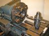
| KWIL | 14/03/2016 20:09:38 |
| 3681 forum posts 70 photos |
16mm boring bar on Myford QCTP (non standard size holder) |
| Ajohnw | 14/03/2016 20:10:01 |
| 3631 forum posts 160 photos | In some ways it is Jason as under the tool there is metal and under that is the compound slide. No dangley bits that apply loads via a lever action but frankly on these sizes of lathes I'm not convinced that matters. The old style 4 way tool post is theoretically more rigid than a qctp for the same reason. In principle solid metal all the way from the tool to lathe bed. They do have a bit of a draw back for smaller indexed tip boring bars especially. The holes as the article shows are made from the spindle which puts them on centre height so if a boring bar is fitted that has it's tip at 1/2 the dia up any deflection will cause the tool to dig in more - more deflection and etc. It is possible to tilt them a touch but this reduces the front clearance on the tip so there isn't that much scope for doing this. So in a nutshell if it allows a bigger bar to be used than can be put into the qctp great with a but. With one lathe I had I toyed with the idea of making something that took capstan sleeves. It would also be possible to make slight eccentric sleeves to carry boring bars. The eccentricity could be used to adjust the tip height, It would be a lot easier to make than the one I posted a photo of. John - |
| Ajohnw | 14/03/2016 20:13:01 |
| 3631 forum posts 160 photos | Posted by KWIL on 14/03/2016 20:09:38:
16mm boring bar on Myford QCTP (non standard size holder) Where from. I have looked all over the place but wont machine more of the normal holders. Not keen on setting up the angles on the blocks to the required level of accuracy either. It's more the sort of job for a horizontal miller with correctly ground cutters. Some on the boxford made lots that way. John - Edited By Ajohnw on 14/03/2016 20:13:21 |
| Michael Gilligan | 14/03/2016 20:13:03 |
23121 forum posts 1360 photos | Jason, You're moving the goalposts a bit, aren't you ? A 'Gibraltar' version, to mount on the Myford cross slide would make a lot of sense, I think. MichaelG. . As for 'Dickson' tool posts: The originals were good [albeit quite small] in the Myford size ... but recent disussion suggests that the "clones" may be far from rigid. . Edit: I'm somewhat confused by the Myford references ... The article refers to it fitting a tee-slotted top slide. Edited By Michael Gilligan on 14/03/2016 20:25:57 |
| JasonB | 14/03/2016 20:58:57 |
25215 forum posts 3105 photos 1 articles | Posted by Michael Gilligan on 14/03/2016 20:13:03:
Edit: I'm somewhat confused by the Myford references ... The article refers to it fitting a tee-slotted top slide. Edited By Michael Gilligan on 14/03/2016 20:25:57 I was going by the colour photo at the beginning which shows one fitted to a Myford Cross slide. If it is just for the topslide then I see even less point in it today, may have been relevant when the old style toolposts were in common use.
Kwil, whats the actual clamping thickness of your 16mm bar allowing for the top & bottom flats? |
| KWIL | 14/03/2016 21:17:19 |
| 3681 forum posts 70 photos | Jason, Boring bar passes through 16mm hole in block, I can check the actuals later. |
| Michael Gilligan | 14/03/2016 21:23:09 |
23121 forum posts 1360 photos | Posted by JasonB on 14/03/2016 20:58:57:
I was going by the colour photo at the beginning which shows one fitted to a Myford Cross slide. . ... and I was going by Mr Downie's articles [which do not] I don't feel qualified to comment on the forthcoming issue of MEW, but the picture shows what I had in mind when I mentioned a 'Gibraltar' version. MichaelG. |
| Neil Wyatt | 14/03/2016 21:29:26 |
19226 forum posts 749 photos 86 articles | It could also be used to hold a fine-finishing tool of the type like a d-bit with top rake. Neil |
| KWIL | 15/03/2016 12:30:04 |
| 3681 forum posts 70 photos | Jason Flat to Flat dimension is 15mm. My Holder is 1.140" in height, Base of holder is 0.255" below flat, 0.3000" above flat and the holder clears thetop slide by0.115". Centre line of Bar to centre bolt of QCTP, 1.9" approx. John Holder home made on vertical mill, angle setting a piece of cake with X & Z DRO readings the same! How many decimal places on angle do you need? K |
| Ajohnw | 15/03/2016 13:40:27 |
| 3631 forum posts 160 photos | I would have thought that they need to be very close, I've never blued one to find out though.
My boxford centre line height from the top of the compound is 1" give or take a few thou. As that's one Myford made boosting the the height of there normal one looks like Myford 7's are 5/8". As 5/8 is more or less 16mm I don't see why one isn't made for these tool posts as on the face of it the part that actually carries the tool could be 5/16 thick top and bottom. The usual odd 0.225 tool support bottom thickness of the normal tool holders would be fine and maybe the top would have to have an odd shape to give sufficient thread for the screws but that isn't much more than the bottom at circa 0.227 on standard holders. Actually the holders seem to be so close to 16mm I have wondered about opening one out rather than milling a bit off the boring bar off. In terms of chatter i usually find it relates to the wall thickness of what I am boring and is reduced by using a heavier bar but will still happen at some wall thickness. It also depends on how the lathe is set up. Any play anywhere will make it worse. That to some extent can be taken up by taking heavier cuts or using a coarser feed which isn't always possible so it makes sense to adjust things as well as they can be. When it comes to flex in the tool holding area it would be interesting to measure it. I never have. In relationship to the compound and the top of the cross slide. I think people would be surprised how little it is even in the case of the heavy cuts posted recently - not the crap finish ones though as that will cause vibration. The cross and compound are likely to have to be set properly. It usually isn't going on lathes I have bought. Sadly headstock bearing can add to play as well but the work deflects instead. Actually years ago I bought this rather large drop forge billet intending to use it for tool holders - dam thing is a bit too small. John - |
| KWIL | 15/03/2016 14:24:37 |
| 3681 forum posts 70 photos | John, If you mount the square machined raw block in the mill vice, you can simply use the X - Z DRO out puts, if when you move the table down by "A" and then need to move the table along by the same "A" to make contact with your probe in the spindle toolholder, then you are at 45 degrees! If not do it again until you are. Thereafter it is coordinate milling to final size and shape. In my case the probe is an electronic one, a mechanical "touch" would be a lot more difficult. I also have DRO on the quill so do not have to move the actual table down. As regards chatter, bar resonances are involved as well, my smaller all carbide one confirms this, but with a VFD and 3ph motor, slight changes of speed works wonders. Edited By KWIL on 15/03/2016 14:26:07 |


Please login to post a reply.
Magazine Locator
Want the latest issue of Model Engineer or Model Engineers' Workshop? Use our magazine locator links to find your nearest stockist!
Sign up to our Newsletter
Sign up to our newsletter and get a free digital issue.
You can unsubscribe at anytime. View our privacy policy at www.mortons.co.uk/privacy
Latest Forum Posts
- *Oct 2023: FORUM MIGRATION TIMELINE*
05/10/2023 07:57:11 - Making ER11 collet chuck
05/10/2023 07:56:24 - What did you do today? 2023
05/10/2023 07:25:01 - Orrery
05/10/2023 06:00:41 - Wera hand-tools
05/10/2023 05:47:07 - New member
05/10/2023 04:40:11 - Problems with external pot on at1 vfd
05/10/2023 00:06:32 - Drain plug
04/10/2023 23:36:17 - digi phase converter for 10 machines.....
04/10/2023 23:13:48 - Winter Storage Of Locomotives
04/10/2023 21:02:11 - More Latest Posts...
- View All Topics
Support Our Partners


Shopping Partners
Subscription Offer

Latest "For Sale" Ads
- Reeves** - Rebuilt Royal Scot by Martin Evans
by John Broughton
£300.00 - BRITANNIA 5" GAUGE James Perrier
by Jon Seabright 1
£2,500.00 - Drill Grinder - for restoration
by Nigel Graham 2
£0.00 - WARCO WM18 MILLING MACHINE
by Alex Chudley
£1,200.00 - MYFORD SUPER 7 LATHE
by Alex Chudley
£2,000.00 - More "For Sale" Ads...
Latest "Wanted" Ads
- D1-3 backplate
by Michael Horley
Price Not Specified - fixed steady for a Colchester bantam mark1 800
by George Jervis
Price Not Specified - lbsc pansy
by JACK SIDEBOTHAM
Price Not Specified - Pratt Burnerd multifit chuck key.
by Tim Riome
Price Not Specified - BANDSAW BLADE WELDER
by HUGH
Price Not Specified - More "Wanted" Ads...
Get In Touch!
Do you want to contact the Model Engineer and Model Engineers' Workshop team?
You can contact us by phone, mail or email about the magazines including becoming a contributor, submitting reader's letters or making queries about articles. You can also get in touch about this website, advertising or other general issues.
Click THIS LINK for full contact details.
For subscription issues please see THIS LINK.
Digital Back Issues


Donate

 Register
 Log-in
Model Engineer Magazine
- Percival Marshall
- M.E. History
- LittleLEC
- M.E. Clock

ME Workshop
- An Adcock
- & Shipley
- Horizontal
- Mill

Subscribe Now
- Great savings
- Delivered to your door

Pre-order your copy!
- Delivered to your doorstep!
- Free UK delivery!
All Forum Topics > Model Engineers' Workshop. > Boring Bar Holder