Forum sponsored by:

Mini Lathe Switch Roulette
| Bill Pudney | 15/10/2015 01:15:35 |
| 622 forum posts 24 photos | I have a well developed hatred of electronics. My usual approach goes along the lines of, "if it's not broken, don't fix it". This has held me in good stead for many years. However, and there's always one of those, now it's failed me. I have just replaced the spindle bearings on my Sieg C3 mini lathe. So the electronics box on the front had to be removed. Imagine my surprise when I realised that virtually ALL of the connections to the Forward/Off/Reverse switch, were not only loose, but in removing the box, had become disconnected. The F/O/R switch has something like 12 connections. I have had a good scratch around trying to find a wiring diagram that shows which wire goes to what numbered terminal. Some of the wiring diagrams show the non switch end of the wire, but no diagrams indicate which terminals they are supposed to connect to. Does anybody know of a wiring diagram which shows this level of detail?? Back when I was a lad, something like this would have a thing called a "Wire List" which showed every wire, and what terminal each end was connected to. Those days seem to be long gone!! At the moment I have been playing fuse roulette trying to determine the correct connections, to no avail. By the way the lathe was working perfectly (despite the loose connections) when I started the overhaul. Hope that somebody can help. cheers Bill ps Did I mention that I hate electronics?? |
| Robbo | 15/10/2015 13:56:45 |
| 1504 forum posts 142 photos | Bill, The only way I can help is to bump this back up to the top of the page! |
| Chris Shelton | 15/10/2015 14:10:55 |
 92 forum posts 46 photos |
Bill, if you go to the Little Machine Shop website, they have an instruction manual for the Sieg C3 with a wiring diagram included. I do not know if it shows enough detail for you to sort out where the wires should go. HTH |
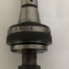
| Ketan Swali | 15/10/2015 14:13:40 |
| 1481 forum posts 149 photos | Hi Bill, I am presuming that you are in Australia, and I am presuming that you actually have a SIEG C3 - brushed motor mini-lathe. Provided at least my presumption about the machine is correct, then here are some pictures below. I too am surprised that the wires just fell out. They are screw on terminals. There must have been a serious amount of vibration over time for this to happen. You better also check the other screw-on terminals too while you are at it.
Ketan at ARC. |
| David Clark 1 | 15/10/2015 14:42:59 |
 3357 forum posts 112 photos 10 articles | Before dismantling any switch gear take a photograph and if necessary make notes. |
| john swift 1 | 15/10/2015 15:15:54 |
 318 forum posts 183 photos | Hi Bill first stop the random tests !! I have the sieg C2 that I had to reverse engineer the speed control board - no one would supply any service information see - **LINK** yes, I found the push on connector used on Chinese machines have a habit of dropping off - too thin and not springy enough
who supplied the lathe webco . chester , warco , axminster ? machines from different suppliers will have variations in the wiring
can you post photos of the loose wires , switch terminals and the control board once the control board is identified and the type of forward / reverse switch it will be easier to give you the help you need
(my lathe has a 4 pole toggle switch to select the motor direction others have a rotary switch the control board used will determine the interlock circuit used )
John one version of the C3 lathe manual -- PS the wires K1 and K2 in Ketans photos are the interlock wires shown in the C3 manual the problem with the motor an speed control board connections to the switch is not all connections are obvious like the jumper between terminals 3 and 7 with some versions rotary cam switches they have internal links so the two switches in each section are connected to form a SPDT switch two of the SPDT elements will only need two links as in the photo to control the motor direction
Edited By john swift 1 on 15/10/2015 15:55:51 |
| Neil Wyatt | 15/10/2015 15:26:41 |
 19226 forum posts 749 photos 86 articles | Do a google image search for 'mini lathe wiring diagram' Unfortunately there are many variants and you will need to be sure you have the right one. On my machine all the wires have numbered tags that match up to the circuit board, and the power leads all use spade connectors that vary in size and gender so you can't connect them the wrong way round. Neil |
| Bill Pudney | 15/10/2015 22:47:41 |
| 622 forum posts 24 photos | Thanks for the responses chaps. I'm in Australia. The machine is a Sieg C3, (180mm x 350mm, or 7" x 14" as the 'Mercans say). I've had it for about 10 years. I had done several searches on the net, using things such as "Sieg C3 lathe wiring diagram". I found a fairly close one on the LMS site. In fact it's pictorially identical to the one in the manual I have, but most of the component and termination idents are different, both diagram to diagram, and either diagram to physical item!! Nowhere are the switch terminations identified!! Thank you Ketan, that switch looks to be identical to the one that is on my machine. I will print this page and do some more re-assembly work. I usually do make a sketch, prior to disassembly, sadly in this case the disassembly work seems to have been semi automatic!! I'm not sure how it happened, the F/O/R switch is about the only part of the machine that has caused a problem. The original one failed after about two weeks (i.e.about 518 weeks ago), was promptly replaced by the supplier, and fitted by me. So the auto disassembly looks as if it's down to me!! I think I must have prepared a sketch to show the connections way back then. Sadly lost now. I will report back after todays efforts. Thanks again cheers Bill |
| john swift 1 | 16/10/2015 01:00:35 |
318 forum posts 183 photos | Hi Bill based on Ketan's photos of the switch I've made a sketch of how I expect the switch contacts to interconnected
John
Edited By john swift 1 on 16/10/2015 01:03:19 |
| Bill Pudney | 16/10/2015 02:09:59 |
| 622 forum posts 24 photos | Well there's good news and bad news. The good news is that I connected up the F/O/R switch i.a.w. Ketans photos, and it worked!! Triffic The bad news is that there is now an intermittent fault. Sometimes, well most times, it will not run "forward". After I've had a cup of coffee I shall go and recheck everything. Thanks again guys cheers Bill |
| Bill Pudney | 16/10/2015 09:20:00 |
| 622 forum posts 24 photos | Now it all seems to be good. The intermittent fault seems to have been one of the spade connectors, that had to be "just so" to work. So it's up and running, at least it will be when the change gear bits have been reassembled. So once again, thanks everyone, it shows the power of the internet!! Cheers Bill |


Please login to post a reply.
Magazine Locator
Want the latest issue of Model Engineer or Model Engineers' Workshop? Use our magazine locator links to find your nearest stockist!
Sign up to our Newsletter
Sign up to our newsletter and get a free digital issue.
You can unsubscribe at anytime. View our privacy policy at www.mortons.co.uk/privacy
Latest Forum Posts
- *Oct 2023: FORUM MIGRATION TIMELINE*
05/10/2023 07:57:11 - Making ER11 collet chuck
05/10/2023 07:56:24 - What did you do today? 2023
05/10/2023 07:25:01 - Orrery
05/10/2023 06:00:41 - Wera hand-tools
05/10/2023 05:47:07 - New member
05/10/2023 04:40:11 - Problems with external pot on at1 vfd
05/10/2023 00:06:32 - Drain plug
04/10/2023 23:36:17 - digi phase converter for 10 machines.....
04/10/2023 23:13:48 - Winter Storage Of Locomotives
04/10/2023 21:02:11 - More Latest Posts...
- View All Topics
Support Our Partners


Shopping Partners
Subscription Offer

Latest "For Sale" Ads
- Reeves** - Rebuilt Royal Scot by Martin Evans
by John Broughton
£300.00 - BRITANNIA 5" GAUGE James Perrier
by Jon Seabright 1
£2,500.00 - Drill Grinder - for restoration
by Nigel Graham 2
£0.00 - WARCO WM18 MILLING MACHINE
by Alex Chudley
£1,200.00 - MYFORD SUPER 7 LATHE
by Alex Chudley
£2,000.00 - More "For Sale" Ads...
Latest "Wanted" Ads
- D1-3 backplate
by Michael Horley
Price Not Specified - fixed steady for a Colchester bantam mark1 800
by George Jervis
Price Not Specified - lbsc pansy
by JACK SIDEBOTHAM
Price Not Specified - Pratt Burnerd multifit chuck key.
by Tim Riome
Price Not Specified - BANDSAW BLADE WELDER
by HUGH
Price Not Specified - More "Wanted" Ads...
Get In Touch!
Do you want to contact the Model Engineer and Model Engineers' Workshop team?
You can contact us by phone, mail or email about the magazines including becoming a contributor, submitting reader's letters or making queries about articles. You can also get in touch about this website, advertising or other general issues.
Click THIS LINK for full contact details.
For subscription issues please see THIS LINK.
Digital Back Issues


Donate

 Register
 Log-in
Model Engineer Magazine
- Percival Marshall
- M.E. History
- LittleLEC
- M.E. Clock

ME Workshop
- An Adcock
- & Shipley
- Horizontal
- Mill

Subscribe Now
- Great savings
- Delivered to your door

Pre-order your copy!
- Delivered to your doorstep!
- Free UK delivery!
All Forum Topics > Help and Assistance! (Offered or Wanted) > Mini Lathe Switch Roulette