Forum sponsored by:

How do I get this apart?
| Simon Collier | 10/06/2015 22:06:30 |
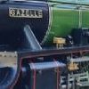 525 forum posts 65 photos | This is from an ML7 I just bought. The knurled ring turns but then tightens again so I can't get it off. I have not tried with force as I don't know what I am doing. Someone among the army of Myford owners out there must know about these. I first posted in an old, relevant thread but got little response. |
| daveb | 10/06/2015 22:27:35 |
| 631 forum posts 14 photos | Adams oiler. I can't see it on your picture but all the ones I've had have a small lever on top. This turns the flow on and off, the knurled sleeve at the top allows you to regulate the drops per minute as viewed trough the circular windows in the base. The knurled sleeve usually screws off but if you simply need to get the plastic dome off, you can lock the knurled sleeve and nut together and unscrew the complete stem from the base. The base and flanged part are swaged together. Dave |
| V8Eng | 10/06/2015 23:37:26 |
| 1826 forum posts 1 photos |
Be careful doing this because the domes on mine were made of glass, I replaced them because the glass cracked. They did not have wicks in them. Adams Oilers are still in business (I think). Sorry I cannot help with dismantling them.
Edited By V8Eng on 10/06/2015 23:38:58 |
| Simon Collier | 11/06/2015 11:06:36 |
525 forum posts 65 photos | I managed to get them apart partly. There were no springs. The diagram in the manual shows springs but no wicks, so they have been modified. The needle screws into the top cap. In one oiler, the needle was so tightly jammed into the brass seat that I needed to use great force to get it out. I can't see the purpose of the (missing) springs except perhaps to hold the cap/needle assembly at the set position. I'll fiddle some more in the morning. |
| Martin Kyte | 11/06/2015 11:42:28 |
 3445 forum posts 62 photos | The way I understand it is:- The spring holds the needle valve shut. The toggle lever on the top lifts it open. (Missing on yours) The knurled adjuster alters the amount of lift and hence the feed. regards Martin |
| Simon Collier | 11/06/2015 12:19:45 |
525 forum posts 65 photos | On this type, there was no toggle lever and the spring cannot be acting to close the needle but rather, bears on the needle adjusting cap, tending to push it open, but of course, it is held by the screw threads. I still don't understand the spring's purpose. |
| KWIL | 11/06/2015 12:35:14 |
| 3681 forum posts 70 photos | Because you have the knurled rings, these were a spring/lever operated drip oil feeder fitted by Myford on ML7 lathes.. Adams used to make a wick feed version which only had a simple oil-in cover cap. Yours have been modified by a.n.other in the past!! Edited By KWIL on 11/06/2015 12:36:01 |
| JasonB | 11/06/2015 13:01:49 |
 25215 forum posts 3105 photos 1 articles | Normally the needle would have a collar or e-clip for the spring to push down on, your needle is not original. The top lever acts like an over centre cam when flat the spring pushes the needle down to stop teh flow, when up the needle lifts, amount of lift and therefore flow is adjusted by teh top knurled cap which the levert bears on. Make them all the time for the hit & miss engines, the spring would fit just above the collar on the needle.
|
| CotswoldsPhil | 11/06/2015 14:02:02 |
 196 forum posts 112 photos | Hi Simon,
What you have are the original Myford drip-feed oilers. No springs, just manual screw adjustment of the needle valve and a little felt filter to catch any foreign bodied in the oil and no wicks in the ones on my machine. The oil just drips straight into the bearings. Here is my ML7 (1965 vintage) fitted with these oilers.
At the start of a session I undid the needle valve screw a couple of turns to get a good drip going and then turned it down to about 3/4 of a turn from closed, setting a regular drip which was visible through the little windows in the base of the oiler. I put an index mark on the top of the knurled knob to help gauge the position of the needle valve. At the end of a session, I gently closed the valves, otherwise, they emptied overnight. One thing I did do was to seal the bowl to plastic cap joint with silicone sealant to stop them leaking, the original cork gasket was not effective. Overall they worked very well, and never thought of replacing them with the flip-top spring activated type. Regards Phil H Edited By CotswoldsPhil on 11/06/2015 14:13:54 |
| Simon Collier | 12/06/2015 02:52:44 |
525 forum posts 65 photos | Thanks Jason for the nice diagram; that explains the "spring closed" type. Phil's is like mine for sure, and mine is a 1964 model, K66083, so close in age too. Thanks Phil for the photo. Yours looks like a posh one with a clutch(?). The only question remaining is whether my felt wicks were added by someone. They look as though they belong but how would you know? I will now turn my worry to how the bearings might have suffered from oil starvation. Without pulling it to bits, how would I know if it is in good order or not? The diagram is from a downloaded ML7 manual and is why I thought there should be a spring. |
| CotswoldsPhil | 12/06/2015 10:44:38 |
196 forum posts 112 photos | Hi Simon, The spring around the needle is to resist the valve turning under vibration, which I missed in my first post. The later ones use a spring loaded lever mechanism to operate the valve. I'm pretty sure the needle was riveted to the knurled knob, and there were no felt wicks; the oil just dripping directly into the hole in the bearing in accordance with the total loss method of lubrication. My ML7 came with the clutch when I bought it back in 1969ish - very handy removing a lot of strain on the motor and switch gear. Its now gone to a new good home being replaced with a Super 7, so did not have the lathe to pull the oiler apart. The oil in your photo looks like motor oil - way too thick and needs ISO 32 Hydraulic oil. See the post lubricating lathes. http://www.model-engineer.co.uk/forums/postings.asp?th=107683 Phil H Edited By CotswoldsPhil on 12/06/2015 10:54:41 |
| Simon Collier | 12/06/2015 22:14:56 |
525 forum posts 65 photos | I read that, thanks Phil. The needle is, in fact, screwed to the cap, 1/8th Whitworth, I worked out. I will track down some correct oil. The previous owner also greased all the oil points too, instead of oiling. A club member gave me a vertical slide for it too a day or so ago, not that I can imagine ever using it seriously, bit it does make it complete for the model making of that era. Simon |


Please login to post a reply.
Magazine Locator
Want the latest issue of Model Engineer or Model Engineers' Workshop? Use our magazine locator links to find your nearest stockist!
Sign up to our Newsletter
Sign up to our newsletter and get a free digital issue.
You can unsubscribe at anytime. View our privacy policy at www.mortons.co.uk/privacy
Latest Forum Posts
- *Oct 2023: FORUM MIGRATION TIMELINE*
05/10/2023 07:57:11 - Making ER11 collet chuck
05/10/2023 07:56:24 - What did you do today? 2023
05/10/2023 07:25:01 - Orrery
05/10/2023 06:00:41 - Wera hand-tools
05/10/2023 05:47:07 - New member
05/10/2023 04:40:11 - Problems with external pot on at1 vfd
05/10/2023 00:06:32 - Drain plug
04/10/2023 23:36:17 - digi phase converter for 10 machines.....
04/10/2023 23:13:48 - Winter Storage Of Locomotives
04/10/2023 21:02:11 - More Latest Posts...
- View All Topics
Support Our Partners


Shopping Partners
Subscription Offer

Latest "For Sale" Ads
- Reeves** - Rebuilt Royal Scot by Martin Evans
by John Broughton
£300.00 - BRITANNIA 5" GAUGE James Perrier
by Jon Seabright 1
£2,500.00 - Drill Grinder - for restoration
by Nigel Graham 2
£0.00 - WARCO WM18 MILLING MACHINE
by Alex Chudley
£1,200.00 - MYFORD SUPER 7 LATHE
by Alex Chudley
£2,000.00 - More "For Sale" Ads...
Latest "Wanted" Ads
- D1-3 backplate
by Michael Horley
Price Not Specified - fixed steady for a Colchester bantam mark1 800
by George Jervis
Price Not Specified - lbsc pansy
by JACK SIDEBOTHAM
Price Not Specified - Pratt Burnerd multifit chuck key.
by Tim Riome
Price Not Specified - BANDSAW BLADE WELDER
by HUGH
Price Not Specified - More "Wanted" Ads...
Get In Touch!
Do you want to contact the Model Engineer and Model Engineers' Workshop team?
You can contact us by phone, mail or email about the magazines including becoming a contributor, submitting reader's letters or making queries about articles. You can also get in touch about this website, advertising or other general issues.
Click THIS LINK for full contact details.
For subscription issues please see THIS LINK.
Digital Back Issues


Donate

 Register
 Log-in
Model Engineer Magazine
- Percival Marshall
- M.E. History
- LittleLEC
- M.E. Clock

ME Workshop
- An Adcock
- & Shipley
- Horizontal
- Mill

Subscribe Now
- Great savings
- Delivered to your door

Pre-order your copy!
- Delivered to your doorstep!
- Free UK delivery!
All Forum Topics > Manual machine tools > How do I get this apart?