Forum sponsored by:

Stuart 10V Build Log - Complete Beginner...
| Dr_GMJN | 17/06/2020 21:56:45 |
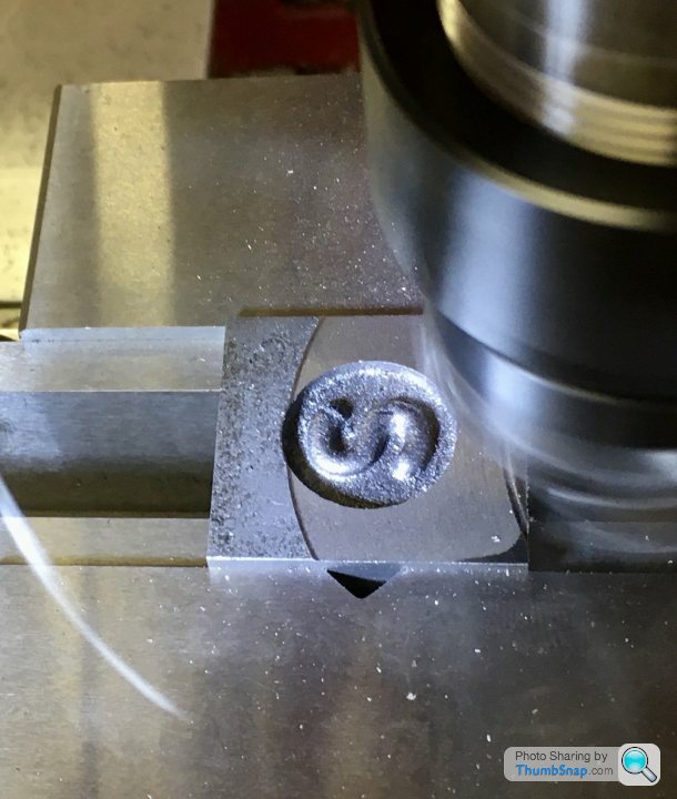
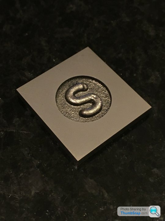
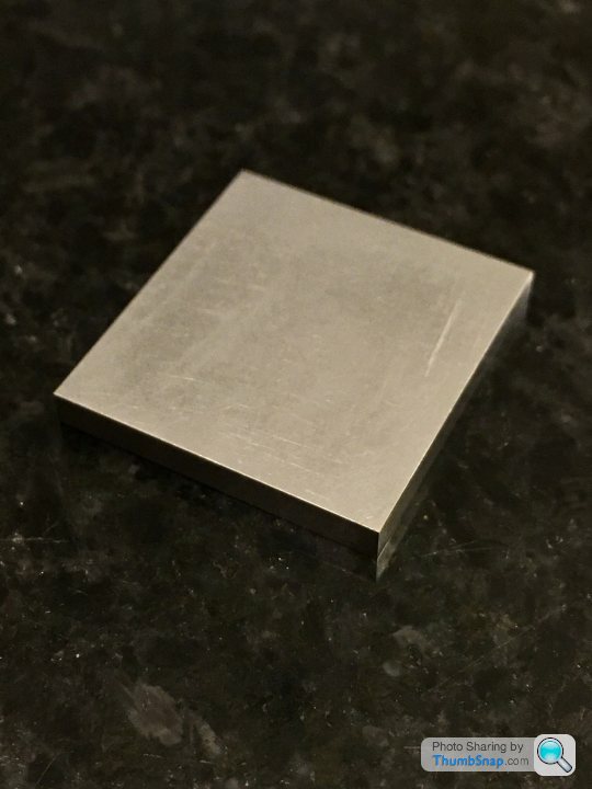
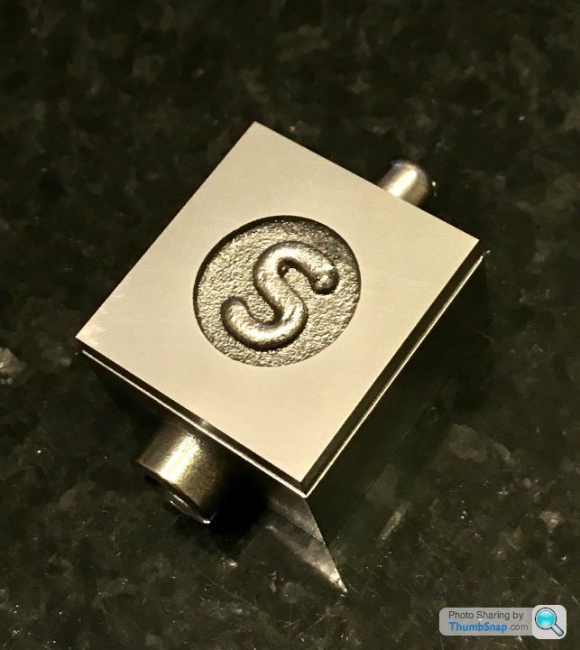
 1602 forum posts | OK guys I'll have a think about it. I don't have a rotary table, and I don't trust my three jaw chuck. Anyway, I didn’t have much time this evening, so I just squared and flatted the valve chest cover. First job was to mill the edges; first opposite pair I face-milled vertically, then clamped those faces horizontally and side-milled the other two. I made sure the “S” Circle was central: |
| Mick B1 | 17/06/2020 22:55:33 |
| 2444 forum posts 139 photos | Posted by Dr_GMJN on 17/06/2020 21:56:45:
... IIRC the calc's on the back of the Zeus booklet. I made my top end cap out of phosphor bronze - I thought it might look nicer. It did for a year or three - now it looks like lightly-rusted steel. But the phosphor bronze tyre I shrink-fitted on the flywheel still looks good. |
| Dr_GMJN | 18/06/2020 10:38:51 |
1602 forum posts | Posted by Mick B1 on 17/06/2020 22:55:33:
Posted by Dr_GMJN on 17/06/2020 21:56:45:
... IIRC the calc's on the back of the Zeus booklet. I made my top end cap out of phosphor bronze - I thought it might look nicer. It did for a year or three - now it looks like lightly-rusted steel. But the phosphor bronze tyre I shrink-fitted on the flywheel still looks good. Thanks, yes, I used the booklet to get the co-ordinates for the motor mount plate PCD holes. The valve cover plate will need to be re-calculated because of it's smaller size, or at least they need carefully checking. |
| Dr_GMJN | 18/06/2020 10:43:57 |
1602 forum posts | I notice there is no oil hole for lubricating the big end on this model, yet there is one for the eccentric. This seems like a potential issue - are there any neat ways of incorporating a method of lubricating the big end? I was also told that the cylinder drain cocks aren't needed, becasue the floating valve allows excess condensed water out. Not sure how, just asking the question. The drain cocks commonly used do look a bit over-sized. Any comments? Also, for the steam inlet and exhaust, can anyone recommend some neat looking brass fittings? I'd like to fit a short exhaust stub - perhaps some thin walled brass tube, and a connection for compressed air. Ideally the pipe connector for the air would be removable for display, perhaps just leaving a threaded or plain bore fitting. I don't want to drill the holes before having the fittings. Thanks. |
| Martin Connelly | 18/06/2020 11:03:59 |
 2549 forum posts 235 photos | Think of them as pre-heating vents rather than as drains. You can allow steam to flow through and get everything hot before running so there will be minimal condensate in the cylinders when first run. It's probably important on a large scale steam engines, not so much on a model that is not really required to be a working engine. You can make your own brass fittings for pipework quite easily. Solder a small ring on the outside diameter near the end of the tube for retention of the tube. Thread the end of a piece of hexagonal brass and drill through for the tube OD and part off the hex bar. If required you can also recess the nut to suit the retaining ring outside diameter. P Martin C |
| JasonB | 18/06/2020 13:12:26 |
 25215 forum posts 3105 photos 1 articles | For air you also need to think about how you will control the volume particularly if your compressor does not have a pressure regulator. I use the push fit fittings for PVC pipe and depending on size of engine will use 4, 6 or 8mm OD pipe. You can either tap the chest and exhaust to take one of these fittings or tap to take a short stubby length of tube and use a double ended connector to push over the metal stub, tube could simply be a rod with hole drilled. Other end of PVC pipe goes to a suitable push fit connector that has a thread to suit your compressor usually 1/* or 1/4 BSP. If you intend to run several engine sthen you can make a manifold. Failing that a simple fitting can be turned up with a barbed end to push a bit of tube on and flow "adjusted" by kinking the tube |
| Martin Connelly | 18/06/2020 13:22:02 |
2549 forum posts 235 photos | Kinking the tube is not very engineery. mole grips are far more impressive Martin C |
| Roderick Jenkins | 18/06/2020 13:35:48 |
 2376 forum posts 800 photos | Those of us from a sciency background would use a tube clamp:
Rod |
| Dr_GMJN | 18/06/2020 17:00:42 |
1602 forum posts | Thanks for the ideas all. I've got a compressor and regulator, and a cut-off tap at the end of the pipe. I use it mainly for airbrushing, so need a controlled supply. |
| Dr_GMJN | 19/06/2020 17:51:17 |
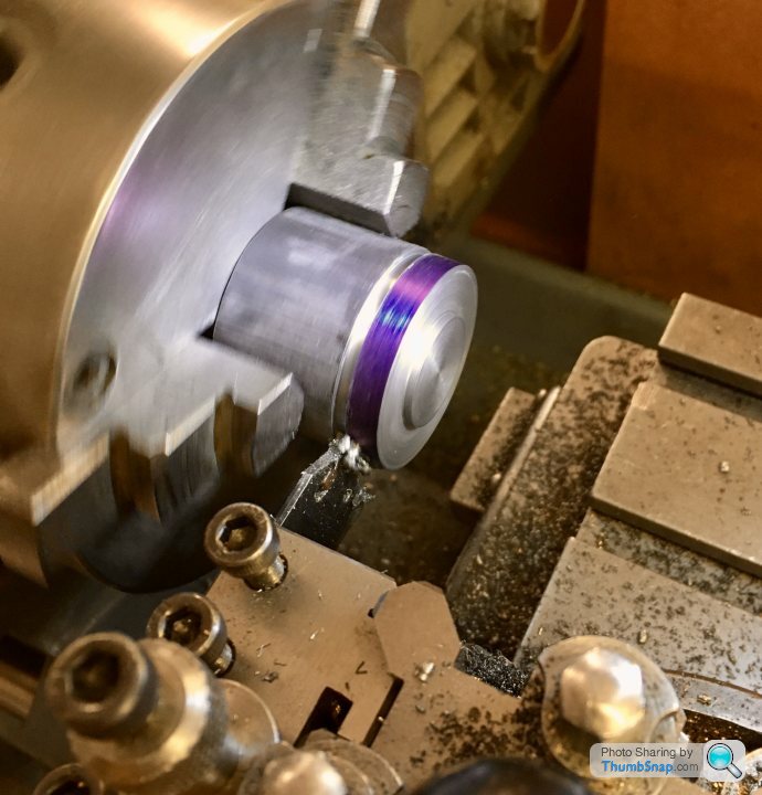
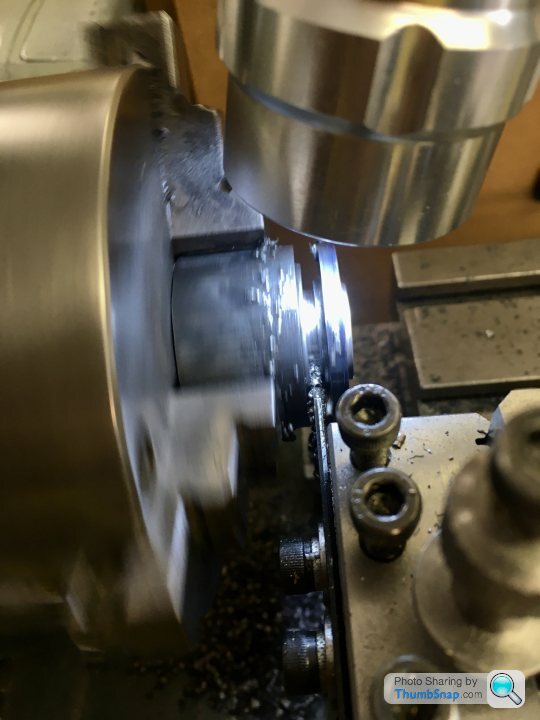
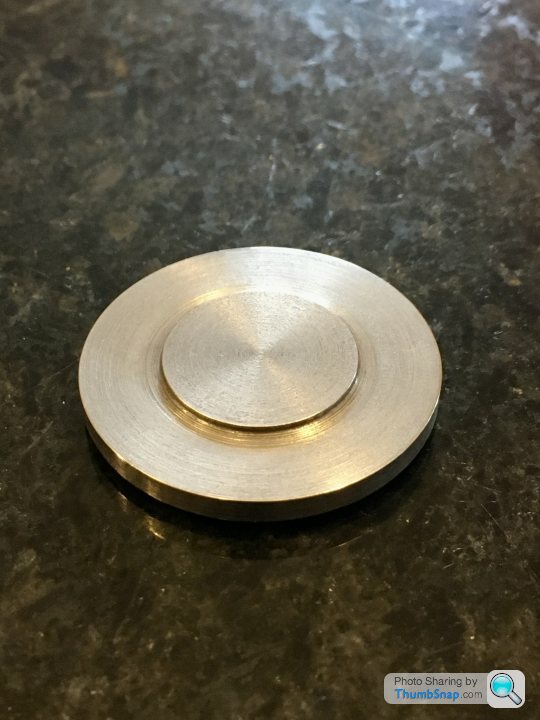
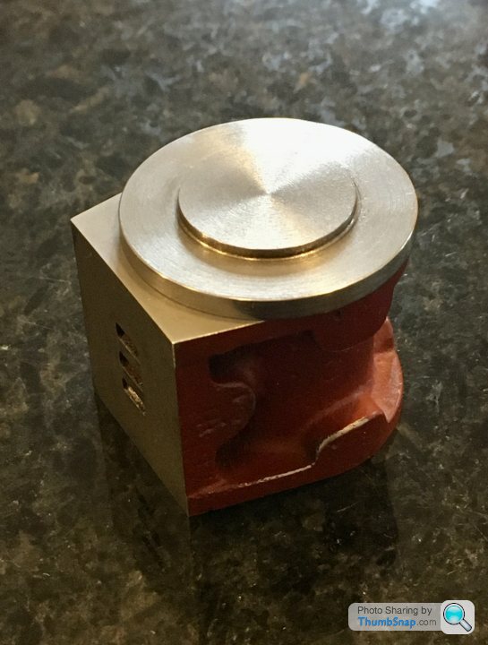
1602 forum posts | So I made a start on the cylinder covers, firstly the top one, because It’s much less critical than the lower. The only feature that’s important is the spigot that fits into the cylinder. Edited By Dr_GMJN on 19/06/2020 17:52:36 |
| JasonB | 19/06/2020 18:37:03 |
25215 forum posts 3105 photos 1 articles | Another option is to make a split bush. Take a short length of stock about 6mm larger diameter than the cover and turn a spigot on the end about 5mm long. Reverse the bush in the chuck so that you are now gripping by the spigot and the larger dia is pushed back against the front of the jaws. Bore right through a couple of mm less than cover diameter and then for about 2mm deep open up to a snug fit on the cover's outer edge. Mark the bush in some way so it goes back into the chuck in the same position before removing and cutting a slot right through it. You can now slip the cover into the recess, put bush into chuck and pushing both back against jaws and step in the bush tighten the chuck. As the recess was turned it will be concentric so provided you put it back in the same position the hole will remain concentric and therefore hold the cover concentric and as the back of the cover has something to register against it won't wobble either.
|
| Dr_GMJN | 19/06/2020 21:08:01 |
1602 forum posts | Posted by JasonB on 19/06/2020 18:37:03:
Another option is to make a split bush. Take a short length of stock about 6mm larger diameter than the cover and turn a spigot on the end about 5mm long. Reverse the bush in the chuck so that you are now gripping by the spigot and the larger dia is pushed back against the front of the jaws. Bore right through a couple of mm less than cover diameter and then for about 2mm deep open up to a snug fit on the cover's outer edge. Mark the bush in some way so it goes back into the chuck in the same position before removing and cutting a slot right through it. You can now slip the cover into the recess, put bush into chuck and pushing both back against jaws and step in the bush tighten the chuck. As the recess was turned it will be concentric so provided you put it back in the same position the hole will remain concentric and therefore hold the cover concentric and as the back of the cover has something to register against it won't wobble either.
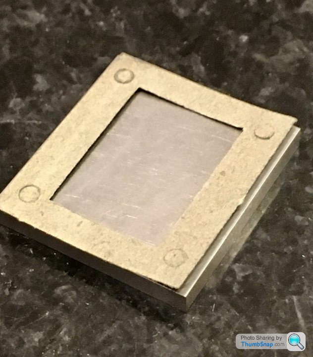
I did think of something like that - but my thinking was as soon as I removed it from the chuck, the precise concentricity might be lost. If it works, I am much happier making that, than the other methods. I suppose I could check concentricity by putting my dial gauge on the outer diameter of the fixture ring? Combined with the the undersized thread...I think this might actually get done this weekend after all. BTW, At some point very soon I'll be drilling all the holes for these components. Some of them have good surface finishes - is it acceptable to put paper between these surfaces and the vice jaws for protection, or shouldn't it matter too much becasue of the polished finish on the jaws? Cheers! Edited By Dr_GMJN on 19/06/2020 21:08:51 |
| JasonB | 20/06/2020 06:47:53 |
25215 forum posts 3105 photos 1 articles | Should not matter as machine vice jaws are smooth so won't mark like a bench vice. Just make sure they are clean of swarf. |
| Danny M2Z | 20/06/2020 08:17:53 |
 963 forum posts 2 photos | For a beginner this is an excellent build log. Thank you very much for posing all the details Dr_GMJN BTW, I often use a slip of paper between vice jaws and the work. Not so much to protect the finish though as it really improves the grip between the components * Danny M * |
| geoff walker 1 | 20/06/2020 16:11:38 |
| 521 forum posts 217 photos | Dr G You can mill the rough cast outer rim of the cylinder concentric with the bore Pass short length of silver steel about 8mm diameter through the bore. Clamp the cylinder in a machine vice but push the bore down on to the s.s bar which will be resting across he top of the vice jaws Take a light skim of the rim with the cutter and lock the cutter Rotate the cylinder a few degrees at a time and take more skims making sure for each skim the bore is resting on the s.s Keep rotating until the whole rim is skimmed and finish with a flat needle file Sorry no photo Geoff |
| Dr_GMJN | 20/06/2020 18:16:07 |
1602 forum posts | Thanks Geoff - I understand. Might give that a go - better than filing from the start. |
| Dr_GMJN | 20/06/2020 23:03:46 |
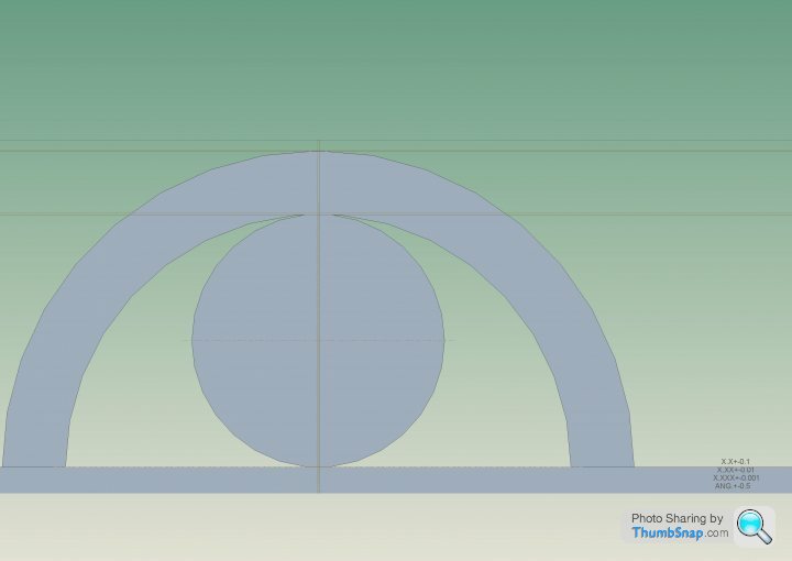
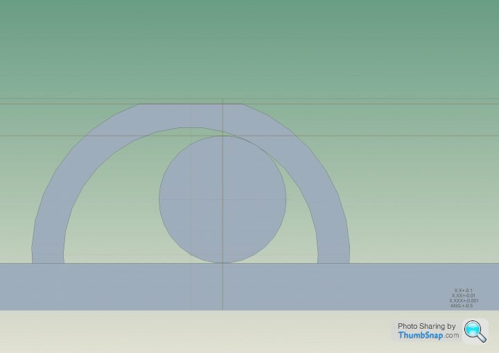
1602 forum posts | Thinking more about Geoff’s cast O/D machining method: Am I right in thinking it would work better for a symmetrical ring than an asymmetric cylinder casting? Because of the port face bulge, it won’t hang vertically on the bar (or at least only at one point), so it would be an estimation job to get the orientation correct to achieve a consistent wall thickness? But if the bar was a fit in the cylinder, all rotational positions around the arced portion would give the correct thickness?
|
| JasonB | 21/06/2020 07:00:29 |
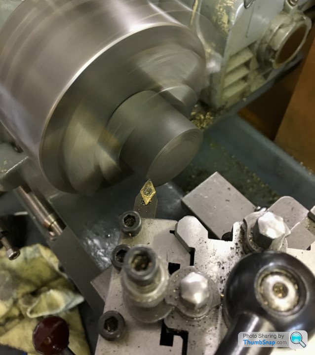
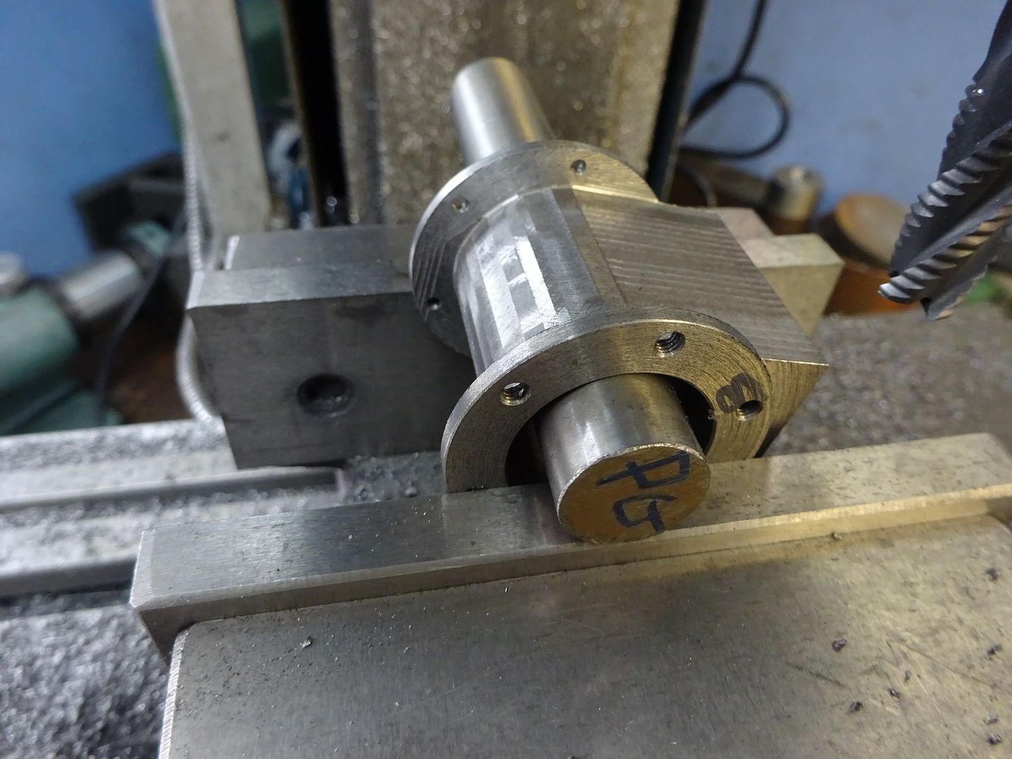
25215 forum posts 3105 photos 1 articles | It does not have to hang vertically, just ensure the work is pushed down against the supporting rod to get a constant thickness. The wall thickness is set by the cutters height above the support bar which remains constant whatever angle the work is at. Here I was making a cylinder from solid and used the method on the smaller diameter, you can see the facets that the method produces.
Quick bit of filing to blend them in.
|
| geoff walker 1 | 21/06/2020 07:16:05 |
| 521 forum posts 217 photos |
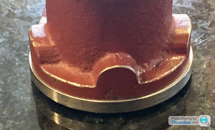
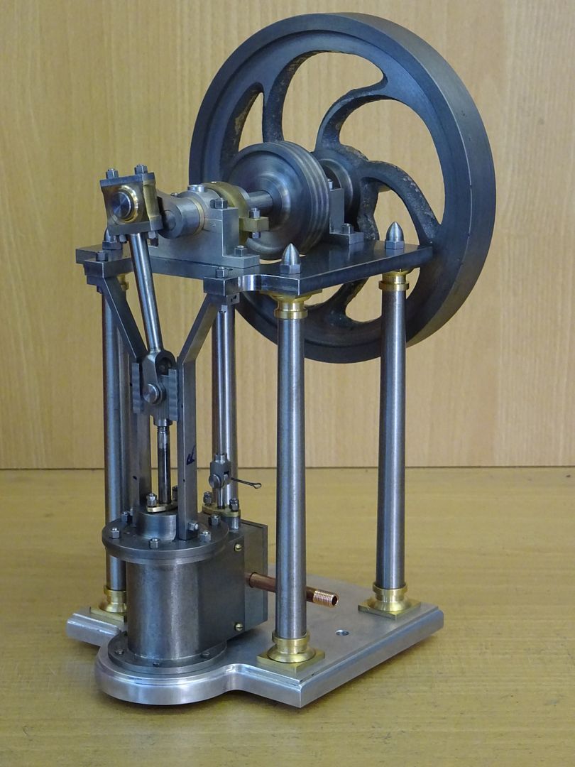
Hi Dr G Trust me and Jason, last post, the method works. Here is a photo of an inverted engine, same one as Jason's which uses a 10v cylinder. You can see the machined outer surface is concentric with the lower cylinder cap. The tapered section is held horizontal in the vice but still with the bore resting on the s.s. bar
Also did the con rod using the same method, 3mm bar through 6.5 hole |
| Dr_GMJN | 21/06/2020 19:00:22 |
1602 forum posts | Thanks Guys - what I meant was this: |


Please login to post a reply.
Magazine Locator
Want the latest issue of Model Engineer or Model Engineers' Workshop? Use our magazine locator links to find your nearest stockist!
Sign up to our Newsletter
Sign up to our newsletter and get a free digital issue.
You can unsubscribe at anytime. View our privacy policy at www.mortons.co.uk/privacy
Latest Forum Posts
- *Oct 2023: FORUM MIGRATION TIMELINE*
05/10/2023 07:57:11 - Making ER11 collet chuck
05/10/2023 07:56:24 - What did you do today? 2023
05/10/2023 07:25:01 - Orrery
05/10/2023 06:00:41 - Wera hand-tools
05/10/2023 05:47:07 - New member
05/10/2023 04:40:11 - Problems with external pot on at1 vfd
05/10/2023 00:06:32 - Drain plug
04/10/2023 23:36:17 - digi phase converter for 10 machines.....
04/10/2023 23:13:48 - Winter Storage Of Locomotives
04/10/2023 21:02:11 - More Latest Posts...
- View All Topics
Support Our Partners


Shopping Partners
Subscription Offer

Latest "For Sale" Ads
- Reeves** - Rebuilt Royal Scot by Martin Evans
by John Broughton
£300.00 - BRITANNIA 5" GAUGE James Perrier
by Jon Seabright 1
£2,500.00 - Drill Grinder - for restoration
by Nigel Graham 2
£0.00 - WARCO WM18 MILLING MACHINE
by Alex Chudley
£1,200.00 - MYFORD SUPER 7 LATHE
by Alex Chudley
£2,000.00 - More "For Sale" Ads...
Latest "Wanted" Ads
- D1-3 backplate
by Michael Horley
Price Not Specified - fixed steady for a Colchester bantam mark1 800
by George Jervis
Price Not Specified - lbsc pansy
by JACK SIDEBOTHAM
Price Not Specified - Pratt Burnerd multifit chuck key.
by Tim Riome
Price Not Specified - BANDSAW BLADE WELDER
by HUGH
Price Not Specified - More "Wanted" Ads...
Get In Touch!
Do you want to contact the Model Engineer and Model Engineers' Workshop team?
You can contact us by phone, mail or email about the magazines including becoming a contributor, submitting reader's letters or making queries about articles. You can also get in touch about this website, advertising or other general issues.
Click THIS LINK for full contact details.
For subscription issues please see THIS LINK.
Digital Back Issues


Donate

 Register
 Log-in
Model Engineer Magazine
- Percival Marshall
- M.E. History
- LittleLEC
- M.E. Clock

ME Workshop
- An Adcock
- & Shipley
- Horizontal
- Mill

Subscribe Now
- Great savings
- Delivered to your door

Pre-order your copy!
- Delivered to your doorstep!
- Free UK delivery!
All Forum Topics > Work In Progress and completed items > Stuart 10V Build Log - Complete Beginner...