Forum sponsored by:

Stirling Engine : Laura
A premilled kit by Bengs
| Brian John | 02/12/2015 06:16:47 |
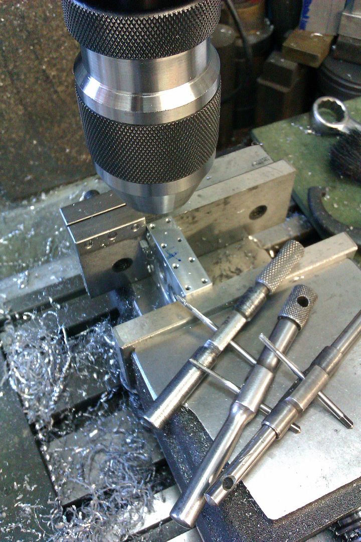
| 1487 forum posts 582 photos | The smaller parts continue to cause problems. This time it is part 30 ; there are six of them to hold the base of the engine above the wooden plinth. The dimensions are not crucial as it is not a moving part of the engine. The instructions call for them to be made out of aluminium. This is awful stuff to drill and tap which is not helped by the fact that my tap wrench is no good for small 2mm taps. I just discovered this today ; it will not grip small taps. In the end I decided to just drill through at 3.2mm and the engine will be held in place with M3 X 30mm socket cap screws which will pass through part 30 down into the wooden base. The M3 nuts will be located in a counter bored hole. This is the way I normally do these things and it avoids unnecessary tapping. I was lucky that I have a brazed carbide tip tool which is exactly 8mm wide ; it is perfect for making the recess cuts. Do you find that aluminium clogs small drill bits and taps ( 2mm or less) ? I will be buying one of these to use with small taps :
Edited By Brian John on 02/12/2015 06:20:41 Edited By Brian John on 02/12/2015 08:36:28 |
| Ian S C | 02/12/2015 12:57:56 |
 7468 forum posts 230 photos | Brian, those bits could be made of anything, wood would be quite OK, drilled right through, and either a bolt through the base board, and nut underneath, or a wood screw into the base board. Ian S C |
| Brian John | 02/12/2015 13:12:05 |
| 1487 forum posts 582 photos | Yes, I know. I even have some M2 X 14mm brass spacers already drilled and tapped which would also work. But they are a hexagonal shape and I decided to keep closely to the original shape. I also wanted to try out that carbide tool on something |
| JasonB | 02/12/2015 13:12:47 |
 25215 forum posts 3105 photos 1 articles | Brian, you can grip the taps by the round shank, the advantage is that if things do get a bit tight then hopefully the tap wrench will slip before the tap snaps. You can also lightly grip tbe bit of exposed round shank in the drill chuck which will help guide the tap true to the bore.
Kerosine when turning, tapping fluid when tapping and as the flutes are not very deep on small taps take the tap out often and clean off the swarf Edited By JasonB on 02/12/2015 13:13:52 |
| Brian John | 02/12/2015 13:33:31 |
| 1487 forum posts 582 photos | I was using the bar type tap wrench which will not grip the smaller taps. I have ordered the T handle type with the chuck for use with smaller taps in future. This was my first attempt at tapping aluminium ; I have only done steel and brass before. I thought aluminium would be easy because it is so soft but I found that it ''sticks'' to the drills bits and taps. |
| Ajohnw | 03/12/2015 10:44:03 |
| 3631 forum posts 160 photos | You should rotate the tap backwards every 1/4 / 1/3 turn to break the chip Brian. A few full turns to start the thread are usually needed but the chip size is small then due to the taper on the tap. There is also the question of how much downward pressure to apply. Can't help you much on that aspect but some is needed otherwise the teeth that have already cut will cut some more due to the cutting forces caused by the new threads that are being cut - they try and push the tap out rather than in. A little pressure is needed in practice, around the same amount that is needed to get the thread to start cutting "crisply" when most of the taper has gone in. I've generally managed by just using 2nd cut and plug taps. The 1st cut one is definitely needed on very hard materials and can be a good idea when very fine tapes are being used. I don't see M2 as being very fine just bordering on that area. The pressure aspect applies to dies too. I have my tin of supa dupa tapping lubricant as well. I'd guess many have. Can't say as I am impressed. I often scrape a bit off a bar of hand soap onto taps. It's a type that has some sort of moisturiser in it. LOL I've mentioned cutting oil several times. People often mention paraffin / kerosene for aluminium. The key word is more volatile than substances used on other materials. It's oily and evaporates readily and that aids cooling which helps prevent the aluminium from melting at machine tool cutting speeds. In practice I have never seen it used. Oil mist and suds yes but never paraffin. The suds tank would have to be emptied and filled up with it. I'd guess if any one really ever used it this way they would also mix in some sort of oil. All I have ever seen been used even when grinding it is lots and lots of suds. John - |
| Neil Wyatt | 03/12/2015 13:50:54 |
 19226 forum posts 749 photos 86 articles | I use a neatcut type oil when tapping aluminium. I've had no problems tapping down to 8BA. 10Ba is trick in ally, but only because the thread is so shallow. |
| Ajohnw | 03/12/2015 15:11:33 |
| 3631 forum posts 160 photos | I wonder if some of the problems with fine taps is down to the depth they are used to. There is one thing common to just about any screw fixing done correctly and that is the relationship between the diameter of the screw and the engagement length with what ever it's screwed into. Nut thickness is a typical example. The relationship us usually just over 1 diameter. Tool rooms I have been involved with shorten bolts if needed so the engagement length is in the range of 1 to 1 1/2 diameters, same order as a nut in other words. Maximum strength. There is no need to tap much deeper than that.
John - |
| Ajohnw | 03/12/2015 19:39:00 |
| 3631 forum posts 160 photos | Taping lubricants always remind me of an instructor that probably trained as a tool maker in the 1930's. He had managed to get a bit of sperm whale oil which was reckoned to be the ultimate tap and die lubricant. It fell into disuse for obvious reasons. From the wiki it seems a "greener" alternative with similar properties is jojoba oil.
John -
|
| Neil Wyatt | 03/12/2015 21:06:33 |
19226 forum posts 749 photos 86 articles | > I wonder if some of the problems with fine taps is down to the depth they are used to. Must agree, I'm sure that most 10BA studs out there go in about 10mm... Neil |
| Ajohnw | 03/12/2015 22:28:32 |
| 3631 forum posts 160 photos | Posted by Neil Wyatt on 03/12/2015 21:06:33:
> I wonder if some of the problems with fine taps is down to the depth they are used to. Must agree, I'm sure that most 10BA studs out there go in about 10mm... Neil Maybe it's down to model " ? engineers ? " Must admit though thinking back to work on car engines studs do go in further than the engagement length of nuts. That's interesting as the reason for nut thickness relates to strength. When tightened both distort due to pitch errors and it's argued that too much engagement length doesn't increase the holding power at all as there will be more distortion.
John - |
| Ajohnw | 03/12/2015 22:56:42 |
| 3631 forum posts 160 photos | They state 1 1/4 D for ferrous and brass, hardness <= or > 160 BHN and 2 1/2 D for other none ferrous, soft stuff such as aluminium and copper I assume. LOL So much for my guess.
John - |
| Ian S C | 04/12/2015 09:39:27 |
7468 forum posts 230 photos | In the small sizes I have a number of taps in the Thread Flow type, no flutes, they form the thread in ductile metals rather than cut them. |
| Brian John | 06/12/2015 05:45:22 |
| 1487 forum posts 582 photos | I made a start on the cylinder covers today but I am having some problems working out the correct order of operations. How would you tackle parts 23 and 24 ? I am also puzzled by the measurement for the displacement cylinder cover (24) where it says 8mm diameter. If this is to fit in the displacement cylinder then I would have thought it should be 14mm (see part 25) ? NOTE : I have just worked four night shifts so maybe my brain is a bit fuzzy : )
|
| JasonB | 06/12/2015 07:44:31 |
25215 forum posts 3105 photos 1 articles | Part 23 Hold material in 3 jaw, face off, cut the 10mm x 1mm spigot, turn outer dia if required, saw/part off. Ideally use soft jaws but a syou don't have these put packing between chuck and work with the just machines face against packing - remove packing before turning on. Face to length, using a tool with 45deg face cut the 8mm decorative spigot, chamfer the outer edge. Mark out 4 lines while held in the lathe and also the hole PCD. |
| Brian John | 19/12/2015 06:23:42 |
| 1487 forum posts 582 photos | I have been in Brisbane for the last nine days and now I am back in Cairns so it time to get back on the lathe.The boring bar arrived yesterday. I had assumed that this could be held directly in the tool post using suitable packing to raise it to the correct height. But now I have a feeling that this should be mounted in a special holder. I just cannot get it to sit right.
Edited By Brian John on 19/12/2015 06:24:26 |
| Martin Connelly | 19/12/2015 08:39:43 |
 2549 forum posts 235 photos | Not sure what you mean by sitting right, the flats on the bar will set the insert to the correct angle. You may need to set the tip slightly above centre line though. I would also suggest a bit of packing on the top face of the bar, it will quickly get chewed up by the clamping screws otherwise. Boring bars need to be set to the minimum necessary stick out for the job being done. This means a lot of clamping and releasing to damage the bar if not protected. If you are using a boring bar with an insert close to the minimum diameter it will fit in you need to look at where the bottom corner of the insert is to make sure it is not rubbing, this is why the tip needs raising sometimes. Martin |
| Brian John | 19/12/2015 09:25:56 |
| 1487 forum posts 582 photos | The insert is not sitting horizontally. I will put some packing on the top as you suggested. Perhaps the clamping screws were throwing it out of alignment. Why does the tip have to be set slightly above the centre line ? |
| JasonB | 19/12/2015 09:35:26 |
25215 forum posts 3105 photos 1 articles | Brian the insert should point down, the flats on teh toolholder will be level when clamped. I set them so the point of the tip is on ctr line then you can face across the bottom of a blind recess.
Edited By JasonB on 19/12/2015 09:41:30 |
| Ajohnw | 19/12/2015 10:47:32 |
| 3631 forum posts 160 photos | The tips should be a SLIGHTLY above centre so that if the bar bends it doesn't dig further into the work making it bend more and dig in even further etc. This is the opposite of turning outside diameters where if the tool bends at all it takes less material providing it's exactly on or a little below centre. Here it's more a case of setting slightly below centre to be more sure that it isn't above. Just good practice in other words unless some one wants to deliberately turn with the tool above centre. Boring bars are far more likely to bend so are more critical in this respect. The amount needed depends on the bar and on the size of the cut. John - |


 Must admit 1D gives me the wobbles so always go for a bit more and also often can't be bothered to shorten screws and bolts. On the other hand 10BA only needs fully tapping to a depth of an 1/8" tops really and that is very likely to save breaking taps.


Please login to post a reply.
Magazine Locator
Want the latest issue of Model Engineer or Model Engineers' Workshop? Use our magazine locator links to find your nearest stockist!
Sign up to our Newsletter
Sign up to our newsletter and get a free digital issue.
You can unsubscribe at anytime. View our privacy policy at www.mortons.co.uk/privacy
Latest Forum Posts
- hemingway ball turner
04/07/2025 14:40:26 - *Oct 2023: FORUM MIGRATION TIMELINE*
05/10/2023 07:57:11 - Making ER11 collet chuck
05/10/2023 07:56:24 - What did you do today? 2023
05/10/2023 07:25:01 - Orrery
05/10/2023 06:00:41 - Wera hand-tools
05/10/2023 05:47:07 - New member
05/10/2023 04:40:11 - Problems with external pot on at1 vfd
05/10/2023 00:06:32 - Drain plug
04/10/2023 23:36:17 - digi phase converter for 10 machines.....
04/10/2023 23:13:48 - More Latest Posts...
- View All Topics
Support Our Partners


Shopping Partners
Subscription Offer

Latest "For Sale" Ads
- Reeves** - Rebuilt Royal Scot by Martin Evans
by John Broughton
£300.00 - BRITANNIA 5" GAUGE James Perrier
by Jon Seabright 1
£2,500.00 - Drill Grinder - for restoration
by Nigel Graham 2
£0.00 - WARCO WM18 MILLING MACHINE
by Alex Chudley
£1,200.00 - MYFORD SUPER 7 LATHE
by Alex Chudley
£2,000.00 - More "For Sale" Ads...
Latest "Wanted" Ads
- D1-3 backplate
by Michael Horley
Price Not Specified - fixed steady for a Colchester bantam mark1 800
by George Jervis
Price Not Specified - lbsc pansy
by JACK SIDEBOTHAM
Price Not Specified - Pratt Burnerd multifit chuck key.
by Tim Riome
Price Not Specified - BANDSAW BLADE WELDER
by HUGH
Price Not Specified - More "Wanted" Ads...
Get In Touch!
Do you want to contact the Model Engineer and Model Engineers' Workshop team?
You can contact us by phone, mail or email about the magazines including becoming a contributor, submitting reader's letters or making queries about articles. You can also get in touch about this website, advertising or other general issues.
Click THIS LINK for full contact details.
For subscription issues please see THIS LINK.
Digital Back Issues


Donate

 Register
 Log-in
Model Engineer Magazine
- Percival Marshall
- M.E. History
- LittleLEC
- M.E. Clock

ME Workshop
- An Adcock
- & Shipley
- Horizontal
- Mill

Subscribe Now
- Great savings
- Delivered to your door

Pre-order your copy!
- Delivered to your doorstep!
- Free UK delivery!
All Forum Topics > Stationary engines > Stirling Engine : Laura