Forum sponsored by:

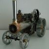
Brian's 1" Minnie Traction Engine
| Brian Abbott | 15/07/2016 12:49:31 |
 523 forum posts 95 photos | Ok, Thanks Jason. |
| Brian Abbott | 16/07/2016 21:53:20 |
523 forum posts 95 photos | Hello. 1" Minnie water gauge issues I have been looking for a piece of 3/16 water gauge tube but only seem to be able to get 5mm If I drill through the top fitting to clear the 5mm tube, say 5.1mm this will be to big for the 7/32x40 tapped hole for the blanking plug, should I look at using a 1/4x40 instead ? Thanks for any thoughts.
|
| JasonB | 17/07/2016 20:21:44 |
 25215 forum posts 3105 photos 1 articles | I think thats about all that can be done, should be enough meat there to take the 1/4" thread |
| Brian Abbott | 08/08/2016 12:44:54 |
523 forum posts 95 photos | Hello all. Jason, did you happen to take any in progress photos when you where machining your cylinder casting on the 1" minnie ? I am after some inspiration on how to go about machining it. Thanks.
|
| JasonB | 08/08/2016 13:08:24 |
25215 forum posts 3105 photos 1 articles | Afraid not brian, it was long before the digital age. I just had the photos and descriptions in Mason's book to go by. |
| Brian Abbott | 08/08/2016 16:09:54 |
523 forum posts 95 photos | Ok, thanks Jason. Bit worried because the casting seems to have a taper down the one side, not sure if i should try and machine the radius.
|
| JasonB | 08/08/2016 16:15:16 |
25215 forum posts 3105 photos 1 articles | I ended up machining every surface of mine. Leave the outside until later then you van mount it on a simple arbor and take a few passes over teh curve to tidy it up. Is your casting just the cylinder block without the saddle? |
| Brian Abbott | 08/08/2016 16:31:28 |
523 forum posts 95 photos | Hello. Yes its got the saddle on, its not a very clear picture sorry, as you say i will machine the 2 bores, then try and true the rest up to it. Thanks. |
| Maurice | 08/08/2016 16:41:59 |
| 469 forum posts 50 photos | Hi Brian, just measured the gauge glass on my Stuart fitting, its slightly under 3/16" dia. Stuarts list 3/16" gauge glass, 2 off 3" pieces for about £4.50 Maurice |
| Richard S2 | 08/08/2016 17:39:34 |
 237 forum posts 135 photos | Hello Brian, I'm sure the Cylinder casting has plenty of spare 'Meat', so don't be worried about the taper. If you first measure up the smaller end and set up to start machining that smaller face and then the bore, you will be ok. I think I have a few pics that may help later, but like Jason, they were before Digital and the WWW !. I'll dig them out and scan them for you if it will help. Regards |
| Brian Abbott | 08/08/2016 22:03:36 |
523 forum posts 95 photos | Hi Maurice, thanks for the info, yes i got some in the end from Stuarts. Richard, if you would not mind scanning them for me when you get a chance i think it would help me. Thanks all. |
| mal webber | 08/08/2016 23:19:37 |
 154 forum posts 309 photos | Hi Brian, there is a build log of a 1" minnie on Traction Talk and the cylinder seems to be the latest couple of posts. hope this helps.
Mal. Edited By mal webber on 08/08/2016 23:21:39 |
| julian atkins | 08/08/2016 23:28:02 |
 1285 forum posts 353 photos | Hi Brian, I have a large quantity of gauge glass. If you know exactly what size you require I am sure I can find a length that suits. Cheers, Julian |
| Richard S2 | 09/08/2016 01:06:10 |
237 forum posts 135 photos | Posted by Brian Abbott on 08/08/2016 22:03:36:
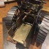
Richard, if you would not mind scanning them for me when you get a chance i think it would help me. Ok, found 2 pics that may help, sorry about quality. Don't know your equipment stock levels, but the pics should be self-explanatory....if not- I used the Vertical Slide for most of the faces, including fly cutting the saddle underside using a 1. 3/8" dia boring bar between centres. In this pic, you can see the thickness of the Saddle face is also tapered (top face not yet machined). Taper is there for a reason and built into the Pattern for retraction from the casting mould.
I used a 4" Rotary Table to machine the top faces of the Saddle (and drill the bolt holes). In this pic the Cylinder is bolted to a slice of machined-to-size Aluminium Bar rather than Mr Mason's method. Set ups may be crude in workshop procedures, but all went fine and accurate for me... being a Dabbling Novice. Hope this helps. Regards.
|
| Richard S2 | 09/08/2016 01:10:11 |
237 forum posts 135 photos | Sorry , forgot the other pic |
| Brian Abbott | 09/08/2016 16:24:26 |
523 forum posts 95 photos | Hello all. Thanks for the info, found the build on the traction talk website, Photos are great Richard, looks like i need to machine the casting all over so the run out should not be a problem so long as there is plenty to clean up. Julian. i managed to get some 3/16 from Stuarts so i should be ok, but thanks for the offer. Cheers. |
| Brian Abbott | 19/09/2016 16:40:54 |
523 forum posts 95 photos | Hello all. After some more advice please. In the process of making the water gauge ( still ) and i need to make some washers just to allow me to nip up the fitting at the correct angle. Should i make these from copper or would aluminium be ok ? Thanks. |
| Mark P. | 19/09/2016 16:59:11 |
 634 forum posts 9 photos | Hi Brian, personally I would use copper washers as spacers. Regards Mark P. |
| Brian Abbott | 03/11/2016 16:45:44 |
523 forum posts 95 photos | Hello All. Can i please ask some advice regarding the positioning of the tender on my 1" Minnie. Position the bottom edge of the strengthening plate level with the bottom edge of the horn plate and spot the holes through. Then position the top edge of the strengthening plate level with the top edge of the tender side and spot through ? Thanks for any help.
|
| JasonB | 03/11/2016 17:11:15 |
25215 forum posts 3105 photos 1 articles | Can't remember how I did mine but probably as per the book which says mark both out from the hornplates. So I would do as you say for the strengthening plates and while they are against the hornplates mark their top and front edges on the hornplates. Then slip the tender over the hornplate and position it to these lines and then mark it from the holes in teh hornplates. With both the strengthening plates and tender drilled the draw strap is clamped between the two and marked out. |


Please login to post a reply.
Magazine Locator
Want the latest issue of Model Engineer or Model Engineers' Workshop? Use our magazine locator links to find your nearest stockist!
Sign up to our Newsletter
Sign up to our newsletter and get a free digital issue.
You can unsubscribe at anytime. View our privacy policy at www.mortons.co.uk/privacy
Latest Forum Posts
- hemingway ball turner
04/07/2025 14:40:26 - *Oct 2023: FORUM MIGRATION TIMELINE*
05/10/2023 07:57:11 - Making ER11 collet chuck
05/10/2023 07:56:24 - What did you do today? 2023
05/10/2023 07:25:01 - Orrery
05/10/2023 06:00:41 - Wera hand-tools
05/10/2023 05:47:07 - New member
05/10/2023 04:40:11 - Problems with external pot on at1 vfd
05/10/2023 00:06:32 - Drain plug
04/10/2023 23:36:17 - digi phase converter for 10 machines.....
04/10/2023 23:13:48 - More Latest Posts...
- View All Topics
Support Our Partners


Shopping Partners
Subscription Offer

Latest "For Sale" Ads
- Reeves** - Rebuilt Royal Scot by Martin Evans
by John Broughton
£300.00 - BRITANNIA 5" GAUGE James Perrier
by Jon Seabright 1
£2,500.00 - Drill Grinder - for restoration
by Nigel Graham 2
£0.00 - WARCO WM18 MILLING MACHINE
by Alex Chudley
£1,200.00 - MYFORD SUPER 7 LATHE
by Alex Chudley
£2,000.00 - More "For Sale" Ads...
Latest "Wanted" Ads
- D1-3 backplate
by Michael Horley
Price Not Specified - fixed steady for a Colchester bantam mark1 800
by George Jervis
Price Not Specified - lbsc pansy
by JACK SIDEBOTHAM
Price Not Specified - Pratt Burnerd multifit chuck key.
by Tim Riome
Price Not Specified - BANDSAW BLADE WELDER
by HUGH
Price Not Specified - More "Wanted" Ads...
Get In Touch!
Do you want to contact the Model Engineer and Model Engineers' Workshop team?
You can contact us by phone, mail or email about the magazines including becoming a contributor, submitting reader's letters or making queries about articles. You can also get in touch about this website, advertising or other general issues.
Click THIS LINK for full contact details.
For subscription issues please see THIS LINK.
Digital Back Issues


Donate

 Register
 Log-in
Model Engineer Magazine
- Percival Marshall
- M.E. History
- LittleLEC
- M.E. Clock

ME Workshop
- An Adcock
- & Shipley
- Horizontal
- Mill

Subscribe Now
- Great savings
- Delivered to your door

Pre-order your copy!
- Delivered to your doorstep!
- Free UK delivery!
All Forum Topics > Traction engines > Brian's 1" Minnie Traction Engine